Abarth Grande Punto 2010 Owner handbook (in English)
Manufacturer: ABARTH, Model Year: 2010, Model line: Grande Punto, Model: Abarth Grande Punto 2010Pages: 207, PDF Size: 3.01 MB
Page 81 of 207
ESP SYSTEM ACTIVATION
The ESP system is automatically activat-
ed when the car is started and cannot be
de-activated.
FAILURE INDICATIONS
In the event of failure, the ESP system is
automatically disconnected, the warning
light
á, comes on with fixed light on the
instrument panel, together with the mes-
sage on the multifunction display (where
provided) (see section “Warning lights and
messages”) and with the button led ASR
OFF. In this case contact a Abarth Deal-
ership as soon as possible.
Performance of the ESP sys-
tem, in terms of active safe-
ty should not induce the driver to take
pointless and unnecessary risks. The
style of driving must in any case al-
ways be adapted to the conditions of
the road surface, visibility and traffic.
Road safety is always the driver’s re-
sponsibility.
WARNING
79
SAFETY
DEVICES
CORRECT USE
OF THE CAR
WARNING
LIGHTS AND
MESSAGES
IIN AN
EMERGENCY
CAR
MAINTENANCE
TECHNICAL
SPECIFICATIONS
INDEX
DASHBOARD
AND CONTROLS
HILL HOLDER SYSTEM
This system is an integral part of the ESP
system and it is provided to facilitate start-
ing on slopes.
It will activate automatically with the fol-
lowing conditions:
❒uphill: vehicle stationary on a road with
a gradient of more than 5%, engine run-
ning, brake pressed and gearbox in neu-
tral or gear other than reverse engaged;
❒downhill: vehicle stationary on a road
with a gradient of more than 5%, engine
running, brake pressed and reverse gear
engaged.
Page 82 of 207
80
SAFETY
DEVICES
CORRECT USE
OF THE CAR
WARNING
LIGHTS AND
MESSAGES
IN AN
EMERGENCY
CAR
MAINTENANCE
TECHNICAL
SPECIFICATIONS
INDEX
DASHBOARD
AND CONTROLS
FAILURE INDICATIONS
System failure is indicated by the turning
on of warning light *on the instrument
panel with digital display and warning light
áon the instrument panel with multi-
function display (where provided) (see
section “Warning lights and messages”).
IMPORANT The Hill Holder system is not
a parking brake therefore, never leave the
car without having engaged the handbrake,
turned the engine off and engaged the first
speed.
For correct operation of the
ESP and ASR systems, the
tyres must absolutely be of the same
brand and type on all wheels, in per-
fect conditions and, above all, of
type, brand and size specified.
WARNINGAt pickup the ESP system control unit will
keep brake force on wheels until reaching
the torque suitable for starting, or in any
case for max. 2 seconds in order to pass
easily from the brake pedal to the accel-
erator pedal.
After two seconds without starting, the
system will deactivate automatically by re-
leasing gradually the brake force.
At releasing, the typical brake disengage-
ment noise indicating that the car is go-
ing to move will be heard.
Page 83 of 207
81
SAFETY
DEVICES
CORRECT USE
OF THE CAR
WARNING
LIGHTS AND
MESSAGES
IIN AN
EMERGENCY
CAR
MAINTENANCE
TECHNICAL
SPECIFICATIONS
INDEX
DASHBOARD
AND CONTROLS
For correct operation of the
ESP and ASR systems, the
tyres must absolutely be of the same
brand and type on all wheels, in per-
fect conditions and, above all, of
type, brand and size specified.
WARNINGASR SYSTEM (Antislip Regulator)
The ASR function controls car drive and
cuts in automatically every time one or
both driving wheels slip.
According to slipping conditions, two dif-
ferent control systems are activated:
❒if slipping involves both driving wheels,
the ASR function intervenes reducing
the power transmitted by the engine;
❒if the slipping involves only one driving
wheel, the ASR system cuts in auto-
matically braking the wheel that is slip-
ping. The action of the ASR is particularly help-
ful in the following circumstances:
❒ slipping of the inner wheel due to the
effect of dynamic load changes or ex-
cessive acceleration;
❒ too much power transmitted to the
wheels also in relation to the conditions
of the road surface;
❒ acceleration on slippery, snowy or
frozen surfaces;
❒ in the case of loss of grip on a wet sur-
face (aquaplaning).
Page 84 of 207

82
SAFETY
DEVICES
CORRECT USE
OF THE CAR
WARNING
LIGHTS AND
MESSAGES
IN AN
EMERGENCY
CAR
MAINTENANCE
TECHNICAL
SPECIFICATIONS
INDEX
DASHBOARD
AND CONTROLS
MSR system (engine braking
torque control)
It is an integral part of the ASR system that
in case of sudden gear shifting, cuts in pro-
viding torque to the engine thus prevent-
ing excessive driving wheel drive that, spe-
cially in poor grip conditions, can lead to
loss of stability.
Switching the systemon/off fig. 96
The ASR system switches on automatically
each time the engine is started.
When travelling, the ASR can be switched
off and on again pressing button Aset on
the dashboard fig. 96.
fig. 96F0M078Ab
When the ASR is switched off this is
shown by the lighting up of the led on the
button and by relevant message on the
multifunction display, where provided.
If the ASR is switched off when travelling,
it will turn on again automatically the next
time the engine is started.
When travelling on snowy roads with
snow chains, it may be helpful to turn the
ASR off: in fact, in these conditions, slip-
ping of the driving wheels when moving off
makes it possible to obtain better drive.
Page 85 of 207
83
SAFETY
DEVICES
CORRECT USE
OF THE CAR
WARNING
LIGHTS AND
MESSAGES
IIN AN
EMERGENCY
CAR
MAINTENANCE
TECHNICAL
SPECIFICATIONS
INDEX
DASHBOARD
AND CONTROLS
The performance of the sys-
tem, in terms of active safe-
ty should not induce the driver to take
pointless and unnecessary risks. The
style of driving must in any case al-
ways be adapted to the conditions of
the road surface, visibility an traffic.
Road safety is always the driver’s re-
sponsibility.
WARNING
For correct operation of the ASR system,
the tyres must absolutely be of the same
brand and type on all wheels, in perfect
conditions and, above all, of type, brand
and size specified.
FAILURE INDICATIONS
In the event of malfunctioning, the ASR
system is automatically disconnected and
the warning light
áwill come with fixed
light on the instrument panel together
with the message on the multifunction dis-
play, where provided, (see section “Warn-
ing lights and messages”). In this case con-
tact Abarth Dealership as soon as possi-
ble.
EOBD SYSTEM
The EOBD system (European On Board
Diagnosis) allows continuous diagnosis of
the components of the car correlated with
emissions.
It also alerts the driver, by turning on the
warning light
Uon the instrument pan-
el (together with relevant message on the
multifunction display, where provided)
(see section “Warning lights and mes-
sages”), when these conditions are no
longer in peak conditions.
The objective is:
❒to keep the system efficiency under con-
trol;
❒warn when a fault causes emissions lev-
els to increase;
❒warn of the need to replace deteriorat-
ed components.
The system also has a diagnostic connec-
tor that can be interfaced with appropriate
tools, which makes it possible to read the
error codes stored in the control unit, to-
gether with a series of specific parameters
for engine operation and diagnosis. This
check can also be carried out by the traf-
fic police.IMPORTANT After eliminating the incon-
venience, to check the system completely,
Abarth Dealerships are obliged to run a
bench test and, if necessary, road tests
which may also call for a long journey.
If turning the ignition key to
MAR, the warning light
Udoes not turn on or if, while
travelling it turns on glowing
steadily or flashing (together with the
message on the multifunction display,
where provided), contact Abarth Deal-
ership as soon as possible. Warning
light
Uoperation can be checked by
means of special equipment by traffic
agents. Always comply with the traffic
regulations in force in the country
where you are travelling.
Page 86 of 207
84
SAFETY
DEVICES
CORRECT USE
OF THE CAR
WARNING
LIGHTS AND
MESSAGES
IN AN
EMERGENCY
CAR
MAINTENANCE
TECHNICAL
SPECIFICATIONS
INDEX
DASHBOARD
AND CONTROLS
TYRE PRESSURE
MONITORING
SYSTEM - T.P.M.S.
(for versions/markets,
where provided)
The car can be equipped with the T.P.M.S.
(Tyre Pressure Monitoring System). This
system consists of a radio-frequency sen-
sor, installed on each wheel (on the rim
inside the tyre) that sends pressure infor-
mation to the control unit.IMPORTANT NOTES ABOUT
THE T.P.M.S. SYSTEM
Failure indications will not be stored and
therefore will not be displayed when turn-
ing the engine off and on again. If failure
persists, the control unit will send warn-
ing indications to the instrument panel on-
ly after a few seconds when the car is
moving.
IMPORTANT Strong radio- frequency
noises could inhibit regular operation of
the T.P.M.S. system. This condition is in-
dicated by a dedicated message on the dis-
play that will disappear automatically as
soon as radio-frequency noises will stop
to disturb the system.
Pay the utmost attention
when checking or inflating
tyres. Excessive pressure impairs road
holding, increases suspension and
wheel stress and causes abnormal
tyre wear.
WARNING
Tyre pressure should be
checked with tyres rested
and cold. Should it become necessary
for whatever reason to check pressure
with hot tyres, do not reduce pressure
although it is higher than the pre-
scribed value but repeat the check
when tyres are cold.
WARNING
The T.P.M.S. system helps
the driver to monitor tyre
pressure since the driver is the always
responsible for proper inflation pres-
sure of tyres and spare wheel (see
paragraph “Wheels” in section “Car
Maintenance”).
WARNING
T.P.M.S. system cannot indi-
cate sudden tyre pressure
drops (e.g.: tyre burst). In this event,
brake the car cautiously and avoid
sudden steering.
WARNING
Page 87 of 207
85
SAFETY
DEVICES
CORRECT USE
OF THE CAR
WARNING
LIGHTS AND
MESSAGES
IIN AN
EMERGENCY
CAR
MAINTENANCE
TECHNICAL
SPECIFICATIONS
INDEX
DASHBOARD
AND CONTROLS
Replacing standard tyres
with winter tyres and vice
versa involves T.P.M.S. system set-up
that shall be performed at Abarth
Dealerships only.
WARNING
The T.P.M.S. system requires
special equipment. Consult
Abarth Dealership to know what type
of accessories are compatible with
the system (wheels, wheel caps, etc.).
Using other accessories could cause
system malfunctioning.
WARNING
Tyre pressure could change
according to outside tem-
perature. For this reason the T.P.M.S.
system could temporarily indicate low
tyre pressure. In this event check pres-
sure with cold tyres and restore prop-
er inflation values if required.
WARNING
If the car is fitted with
T.P.M.S. system, tyre and/or
rim removal and refitting operations
involve special precautions; to pre-
vent damages or wrong sensor refit-
ting, contact Abarth Dealership to
have tyre and/or rim changed.
WARNING
If the car is fitted with
T.P.M.S. system, when chang-
ing a tyre, change also the rubber seal
of the valve. Contact a Abarth Deal-
ership.
WARNING
Strong radio-frequency nois-
es could inhibit the regular
operation of the T.P.M.S. system.
This condition will be indicated by a
message on the multfunction display
(for versions/markets, where provid-
ed). The warning message will go off
automatically as soon as the radio-
frequency noise will stop to disturb
the system.
WARNING
Page 88 of 207

86
SAFETY
DEVICES
CORRECT USE
OF THE CAR
WARNING
LIGHTS AND
MESSAGES
IN AN
EMERGENCY
CAR
MAINTENANCE
TECHNICAL
SPECIFICATIONS
INDEX
DASHBOARD
AND CONTROLS
–
NO
NO
YES
YES
YESYES
YES
YES
NO
NO
NO In order to use the system properly, refer to the following table when you have to change wheels/tyres:
Operation Sensor presence Failure indication Abarth Dealership
service operation
–
Wheel change with spare wheel
Wheel change
with snow tyres
Wheel change
with snow tyres
Wheel change
with others of different
size (*)
Wheel cross switching
(front/rear) (**)
(*) Given as an alternative on the Owner Handbook and available at Lineaccessori Abarth.
(**) Not cross switched (tyres shall stay on the same side).Contact Abarth
Dealership
Repair damaged
wheel
Contact Abarth
Dealership
–
–
Page 89 of 207
87
SAFETY
DEVICES
CORRECT USE
OF THE CAR
WARNING
LIGHTS AND
MESSAGES
IIN AN
EMERGENCY
CAR
MAINTENANCE
TECHNICAL
SPECIFICATIONS
INDEX
DASHBOARD
AND CONTROLS
SPORT BOOST
The vehicle is equipped with a system al-
lowing to choose between two driving
modes: normal and sporting.
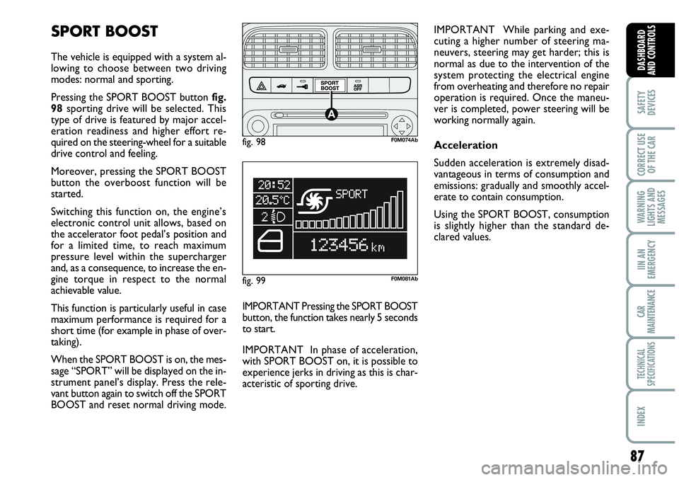
Pressing the SPORT BOOST button fig.
98sporting drive will be selected. This
type of drive is featured by major accel-
eration readiness and higher effort re-
quired on the steering-wheel for a suitable
drive control and feeling.
Moreover, pressing the SPORT BOOST
button the overboost function will be
started.
Switching this function on, the engine’s
electronic control unit allows, based on
the accelerator foot pedal’s position and
for a limited time, to reach maximum
pressure level within the supercharger
and, as a consequence, to increase the en-
gine torque in respect to the normal
achievable value.
This function is particularly useful in case
maximum performance is required for a
short time (for example in phase of over-
taking).
When the SPORT BOOST is on, the mes-
sage “SPORT” will be displayed on the in-
strument panel’s display. Press the rele-
vant button again to switch off the SPORT
BOOST and reset normal driving mode. IMPORTANT While parking and exe-
cuting a higher number of steering ma-
neuvers, steering may get harder; this is
normal as due to the intervention of the
system protecting the electrical engine
from overheating and therefore no repair
operation is required. Once the maneu-
ver is completed, power steering will be
working normally again.
Acceleration
Sudden acceleration is extremely disad-
vantageous in terms of consumption and
emissions: gradually and smoothly accel-
erate to contain consumption.
Using the SPORT BOOST, consumption
is slightly higher than the standard de-
clared values.
IMPORTANT Pressing the SPORT BOOST
button, the function takes nearly 5 seconds
to start.
IMPORTANT In phase of acceleration,
with SPORT BOOST on, it is possible to
experience jerks in driving as this is char-
acteristic of sporting drive.
fig. 98F0M074Ab
fig. 99F0M081Ab
Page 90 of 207
ACCESSORIES
PURCHASED
BY THE OWNER
If after buying the car, you decide to install
electrical accessories that require a per-
manent electric supply (alarm, satellite an-
titheft system, etc.) or accessories that in
any case burden the electric supply, con-
tact Abarth Dealership, whose qualified
personnel, besides suggesting the most
suitable devices belonging to Lineaccessori
Abarth, will also evaluate the overall elec-
tric absorption, checking whether the car’s
electric system is able to withstand the
load required, or whether it needs to be
integrated with a more powerful battery.
Take care when fitting addi-
tional spoilers, alloy rims and
non-standard wheel caps: they might
reduce ventilation of the brakes, thus
their efficiency, during abrupt and re-
peated braking, or long downhill
slopes. Make sure that nothing (mats,
etc.) gets in the way of the pedals
when they are pushed down.
WARNING
INSTALLATION OF
ELECTRIC/ELECTRONIC
DEVICES
Electric/electronic devices installed after
buying the vehicle and in after-market shall
bear the following marking:
Fiat Auto S.p.A. authorizes the installation
of transceivers, provided that installation
is workmanlike performed in compliance
with Manufacturer’s specifications at a spe-
cialised service centre.
IMPORTANT The installation of devices
involving modifications of vehicle charac-
teristics may determine the withdrawal of
the driving licence by the appointed pub-
lic authorities and the forfeiture of the
warranty as concerns defects/failures due
to said modification or leading directly or
indirectly to it.
Fiat Auto S.p.A. declines all responsibility
due to damages connected with the in-
stallation of accessories/devices not sup-
plied by or recommended by Fiat Auto
S.p.A. and installed not in compliance with
the specified prescriptions.
88
SAFETY
DEVICES
CORRECT USE
OF THE CAR
WARNING
LIGHTS AND
MESSAGES
IN AN
EMERGENCY
CAR
MAINTENANCE
TECHNICAL
SPECIFICATIONS
INDEX
DASHBOARD
AND CONTROLS
fig. 99/aF0M0431m
WIRING FOR
NAVIGATION SYSTEM
(MY PORT)
(for versions/markets,
where provided)
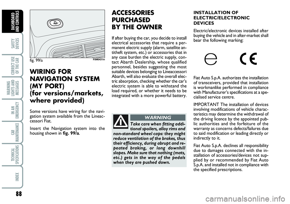
Some versions have wiring for the navi-
gation system available from the Lineac-
cessori Fiat.
Insert the Navigation system into the
housing shown in fig. 99/a.