mirror controls Abarth Grande Punto 2010 Owner handbook (in English)
[x] Cancel search | Manufacturer: ABARTH, Model Year: 2010, Model line: Grande Punto, Model: Abarth Grande Punto 2010Pages: 207, PDF Size: 3.01 MB
Page 6 of 207
4
SAFETY
DEVICES
CORRECT USE
OF THE CAR
WARNING
LIGHTS AND
MESSAGES
IN AN
EMERGENCY
CAR
MAINTENANCE
TECHNICAL
SPECIFICATIONS
INDEX
DASHBOARD
AND CONTROLSDASHBOARD ...................................................................... 5
SYMBOLS ............................................................................... 7
THE FIAT CODE SYSTEM.................................................. 7
THE KEYS .............................................................................. 8
ALARM ................................................................................... 11
IGNITION DEVICE .............................................................. 12
INSTRUMENT PANEL ........................................................ 13
INSTRUMENTS..................................................................... 14
RECONFIGURABLE MULTIFUNCTION DISPLAY .... 16
TRIP COMPUTER ................................................................ 25
FRONT SEATS ..................................................................... 28
REAR SEATS .......................................................................... 29
HEAD RESTRAINTS............................................................. 30
STEERING WHEEL .............................................................. 31
REARVIEW MIRRORS......................................................... 31
CLIMATE CONTROL.......................................................... 33
MANUAL CLIMATE CONTROL SYSTEM .................... 34
AUTOMATIC TWO-ZONE CLIMATE
CONTROL SYSTEM ........................................................... 40
EXTERNAL LIGHTS............................................................. 47
WINDOW WASHING....................................................... 49
CRUISE CONTROL ............................................................ 52CEILING LIGHTS.................................................................. 54
CONTROLS ........................................................................... 55
FUEL CUT-OFF SWITCH .................................................. 57
INTERIOR FITTINGS........................................................... 58
SKY-DOME SUNROOF ..................................................... 62
DOORS .................................................................................. 64
POWER WINDOWS/WINDOW WINDERS .............. 66
BOOT ...................................................................................... 68
BONNET................................................................................. 71
ROOF RACK/SKI RACK .................................................... 73
HEADLIGHTS........................................................................ 74
ABS SYSTEM ......................................................................... 76
ESP SYSTEM .......................................................................... 78
EOBD SYSTEM ..................................................................... 83
TYRE PRESSURE MONITORING SYSTEM - T.P.M.S. . 84
SPORT BOOST..................................................................... 87
WIRING FOR NAVIGATION SYSTEM ......................... 88
ACCESSORIES PURCHASED BY THE OWNER .......... 88
AT THE FILLING STATION ............................................. 89
PROTECTING THE ENVIRONMENT............................. 90
D D
A A
S S
H H
B B
O O
A A
R R
D D
A A
N N
D D
C C
O O
N N
T T
R R
O O
L L
S S
Page 33 of 207
31
SAFETY
DEVICES
CORRECT USE
OF THE CAR
WARNING
LIGHTS AND
MESSAGES
IIN AN
EMERGENCY
CAR
MAINTENANCE
TECHNICAL
SPECIFICATIONS
INDEX
DASHBOARD
AND CONTROLS
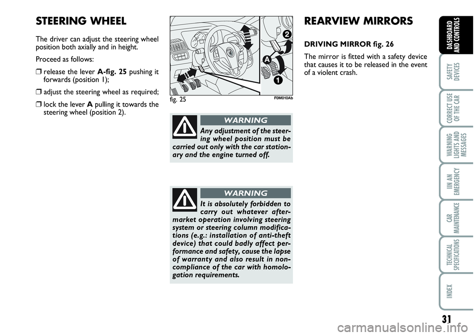
STEERING WHEEL
The driver can adjust the steering wheel
position both axially and in height.
Proceed as follows:
❒release the lever A-fig. 25pushing it
forwards (position 1);
❒ adjust the steering wheel as required;
❒lock the lever Apulling it towards the
steering wheel (position 2).fig. 25F0M010Ab
REARVIEW MIRRORS
DRIVING MIRROR fig. 26
The mirror is fitted with a safety device
that causes it to be released in the event
of a violent crash.
Any adjustment of the steer-
ing wheel position must be
carried out only with the car station-
ary and the engine turned off.
WARNING
It is absolutely forbidden to
carry out whatever after-
market operation involving steering
system or steering column modifica-
tions (e.g.: installation of anti-theft
device) that could badly affect per-
formance and safety, cause the lapse
of warranty and also result in non-
compliance of the car with homolo-
gation requirements.
WARNING
Page 34 of 207

32
SAFETY
DEVICES
CORRECT USE
OF THE CAR
WARNING
LIGHTS AND
MESSAGES
IN AN
EMERGENCY
CAR
MAINTENANCE
TECHNICAL
SPECIFICATIONS
INDEX
DASHBOARD
AND CONTROLS
DOOR MIRRORS
Adjustment fig. 27
This operation is only possible with igni-
tion key at MAR.
Proceed as follows:
❒use switch Bto select the mirror re-
quired (left or right);
❒to adjust the mirror move the switch
Cin the four directions.
It can be moved using the lever Ato two
different positions: normal or antiglare.Folding
When required (for example when the
mirror causes difficulty in narrow spaces)
it is possible to fold the mirror moving it
from position 1-fig. 28to position 2.
When driving the mirrors shall
always be in position 1-fig. 28.
As the driver’s door mirror is
curved, it may slightly alter
the perception of distance.
WARNING
Demisting/defrosting
(for versions/markets,
where provided)
Mirrors are fitted with resistors that will
activate when turning the heated rear win-
dow on (by pressing button
().
IMPORTANT This function is timed and
it will turn off automatically a few minutes
later.
fig. 26F0M0028m
fig. 27F0M0030m
fig. 28F0M0250m
Page 40 of 207

38
SAFETY
DEVICES
CORRECT USE
OF THE CAR
WARNING
LIGHTS AND
MESSAGES
IN AN
EMERGENCY
CAR
MAINTENANCE
TECHNICAL
SPECIFICATIONS
INDEX
DASHBOARD
AND CONTROLS
Window demisting
In the event of considerable outside mois-
ture and/or rain and/or considerable dif-
ferences in temperature inside and outside
the passenger compartment, perform the
following preventive demisting procedure:
❒knob Aturned to red section;
❒turn air recirculation off by pressing
button D, button led off;
❒turn knob Cto -or to ®if the win-
dows do not demist;
❒turn knob Bto 2ndspeed.
IMPORTANT The climate control system
is very useful to prevent window misting
up in presence of high humidity since it de-
humidifies the air.HEATED REAR WINDOW
AND DOOR MIRROR
DEMISTING/DEFROSTING
(for versions/markets, where
provided) fig. 33
Press button Ato start this function;
when this function is on the button led is
on.
This function is timed and switches off au-
tomatically after 20 minutes. To cut out
this function press again button A.
IMPORTANT Do not apply stickers on
the inside of the rear window over the
heating filaments to avoid damage that
might cause it to stop working properly. After demisting/defrosting, operate the
controls to keep the required comfort.
IMPORTANT The climate control system
is very useful to speed up demisting since
it dehumidifies the air. Set controls to
demisting function and switch on the cli-
mate control system by pressing button
E; the knob led will turn on.
fig. 33F0M0038m
Page 44 of 207
42
SAFETY
DEVICES
CORRECT USE
OF THE CAR
WARNING
LIGHTS AND
MESSAGES
IN AN
EMERGENCY
CAR
MAINTENANCE
TECHNICAL
SPECIFICATIONS
INDEX
DASHBOARD
AND CONTROLS
During fully automatic operation, the on-
ly manual settings required are the fol-
lowing:
❒MONO, to align the air temperature
and distribution set on the passenger’s
side with that on the driver’s side;
❒•air recirculation, to keep it always
on or off;
❒-to speed up demisting/defrosting of
windscreen, side windows, rear window
and door mirrors;
❒
(to demist/defrost heated rear win-
dow and door mirrors.
During full automatic system operation,
you can change at any time set tempera-
tures, air distribution and fan speed by us-
ing the relevant buttons or knobs: the sys-
tem will automatically change its settings
to adjust to the new requirements.During (FULL AUTO) operation, chang-
ing air distribution and/or flow and/or
compressor activation and/or air recircu-
lation will make the FULLwording dis-
appear. In this way the system will keep
on controlling automatically all functions,
excluding those changed manually. Fan
speed is the same for every area of the
passenger compartment.
Air temperature adjusting
knobs H - N
Turning the knobs clockwise or counter-
clockwise, respectively highers or lowers
the temperature of the air required re-
spectively in the front left zone (knob N) or
in the right zone (knob H) of the passenger
compartment. Since the system controls
two zones of the passenger compartment,
it is possible to personalise required tem-
peratures (driver and passenger) with a
maximum difference of 7 °C. The temper-
atures set are shown on the displays near
the relevant knobs. Pressing button A
(MONO) automatically aligns the temper-
ature on the passenger’s side with that on
the driver’s side; you can therefore set the
same temperature for both zones by turn-
ing knob Non driver side. Separate oper-
ation of air temperatures and distribution is
restored by turning knobs Hor pressing
again button A(MONO) when the button
led is on.Turn the knobs fully clockwise or counter-
clockwise to engage respectively HI(max-
imum heating) or LO(maximum cooling).
To deactivate these two functions, just
turn the temperature knob and set the re-
quired temperature.
Front air distribution buttons I-M
Pressing these buttons it is possible to
choose manually one of the seven possi-
ble air distributions to the passenger com-
partment (right or left side):NAir flow to the windscreen and front
side window vents to demist or de-
frost them.
˙Air flow at central and side dashboard
vents to ventilate the chest and the
face during the hot season.
OAir flow towards the front and rear
lower parts of the passenger com-
partment. Due to the natural tenden-
cy of heat to spread upwards, this type
of distribution allows heating of the
passenger compartment in the short-
est time, also giving a prompt feeling
of warmth.
Page 48 of 207

46
SAFETY
DEVICES
CORRECT USE
OF THE CAR
WARNING
LIGHTS AND
MESSAGES
IN AN
EMERGENCY
CAR
MAINTENANCE
TECHNICAL
SPECIFICATIONS
INDEX
DASHBOARD
AND CONTROLS
Heated rear window and door
mirror demisting/defrosting button
(for versions/markets,
where provided) G
Press this button to activate heated rear
window demisting/defrosting.
When this function is on, the button led
is on.
This function is timed and switches off au-
tomatically after about 20 minutes or by
pressing again the button or by turning the
engine off. It will not be switched on au-
tomatically when restarting the engine.
IMPORTANT Do not apply stickers on the
inside of the rear window over the heat-
ing filaments to avoid damage that might
cause it to stop working properly.
Switching the climate control
system off (OFF) E
Press button Eto turn the system off.
When turned off the system conditions
are the following:
❒set temperature displays off;
❒air recirculation is on;
❒conditioner compressor off;
❒fan off.
Heated rear window can be turned on or
off also when the system is off.
IMPORTANT The system will store the
temperatures set before turning off and
will resume them when pressing any but-
ton (except heated rear window); if the
function corresponding to the button
pressed is off it will be turned on; if on it
will be kept active.
Press AUTOto turn the system in au-
tomatic mode.ADDITIONAL HEATER
(for versions/markets,
where provided)
This device shall be used to speed up pas-
senger compartment warming when it is
very cold.
The additional heater turns off automati-
cally after reaching the required comfort
conditions.
Automatic two-zone climate
control system
The additional heater will switch on au-
tomatically after turning the ignition key
to ON.
Manual Heater and Climate
control system
The additional heater will switch on au-
tomatically by turning knob Ato the last
red sector and turning the fan on (knob
B) to the first speed at least.
IMPORTANT Heater works only with
low outside temperature and engine
coolant temperature.
IMPORTANT Heater will not turn on if
the battery voltage is not sufficient.
Page 52 of 207
50
SAFETY
DEVICES
CORRECT USE
OF THE CAR
WARNING
LIGHTS AND
MESSAGES
IN AN
EMERGENCY
CAR
MAINTENANCE
TECHNICAL
SPECIFICATIONS
INDEX
DASHBOARD
AND CONTROLS
RAIN SENSOR (for versions/
markets, where provided)
The rain sensor is located behind the dri-
ving mirror in contact with the windscreen
and has the purpose of automatically ad-
just, during the intermittent operation, the
frequency of the windscreen wiper
strokes as to the rain intensity.
IMPORTANT Keep clean the glass in the
sensor area.
Activation
Move the right-hand stalk knurled ring to
≤fig. 37.
The activation of the rain sensor is sig-
nalled by a control acquisition “stroke”.
Through the set up menu it is possible to
increase the sensitivity of the rain sensor.
The increase of the sensitivity of the rain
sensor is signalled by a control and acqui-
sition “stroke”.
Operating the windscreen washer with
the rain sensor activated the normal wash-
ing cycle is performed at the end of which
the rain sensor resumes its normal auto-
matic function.Deactivation
Change the stalk knurled ring position
from
≤fig. 37or turn the ignition key
to STOP.
At next engine starting (key at MAR), the
sensor will not be reactivated even if the
knurled ring is still at
≤fig. 37. To ac-
tivate the rain sensor you have to move
the knurled ring from
≤to another po-
sition and then again to
≤.
Rain sensor activation will be indicated by
at least one wiper “stroke” even if the
windscreen is dry.
The rain sensor is able to recognize and
automatically adjust itself in the presence
of the following particular conditions:
❒ impurities on the controlled surface
(salt, dirt, etc.);
❒difference between day and night.
IMPORTANT Streaks of water may cause
unrequired blade moving. “Smart washing” function
Pulling the stalk towards the steering wheel
(unstable position) operates the wind-
screen washer.
Keeping the stalk pulled for more than half
a second, with just one movement it is
possible to operate the washer jet and the
wiper at the same time.
The wiper stops working three strokes af-
ter releasing the stalk.
A further stroke after 6 seconds com-
pletes the wiping operation.
Page 63 of 207
61
SAFETY
DEVICES
CORRECT USE
OF THE CAR
WARNING
LIGHTS AND
MESSAGES
IIN AN
EMERGENCY
CAR
MAINTENANCE
TECHNICAL
SPECIFICATIONS
INDEX
DASHBOARD
AND CONTROLS
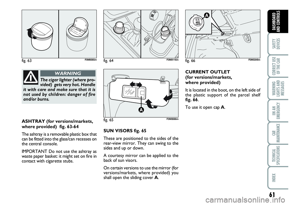
ASHTRAY (for versions/markets,
where provided) fig. 63-64
The ashtray is a removable plastic box that
can be fitted into the glass/can recesses on
the central console.
IMPORTANT Do not use the ashtray as
waste paper basket: it might set on fire in
contact with cigarette stubs.SUN VISORS fig. 65
These are positioned to the sides of the
rear-view mirror. They can swing to the
sides and up or down.
A courtesy mirror can be applied to the
back of sun visors.
On certain versions to use the mirror (for
versions/markets, where provided) you
shall open the sliding cover A.CURRENT OUTLET
(for versions/markets,
where provided)
It is located in the boot, on the left side of
the plastic support of the parcel shelf
fig. 66.
To use it open cap A.
The cigar lighter (where pro-
vided) gets very hot. Handle
it with care and make sure that it is
not used by children: danger of fire
and/or burns.
WARNING
fig. 63F0M0085m
fig. 65F0M0086m
fig. 66F0M0249mfig. 64F0M0116m
Page 118 of 207
116
WARNING
LIGHTS AND
MESSAGES
IN AN
EMERGENCY
CAR
MAINTENANCE
TECHNICAL
SPECIFICATIONS
INDEX
DASHBOARD
AND CONTROLS
SAFETY
DEVICES
CORRECT USE
OF THE CAR
Do not exceed the speed limits of the
country you are driving in. In any case do
not exceed 100 km/h.
Fit a suitable towing stabilizer to the trail-
er to be towed.TOWING TRAILERS
IMPORTANT NOTES
For towing caravans or trailers the car
must be fitted with a certified tow hook
and an adequate electric system. Installa-
tion should be carried out by specialised
personnel who release a special document
for circulation on the road.
Install any specific and/or additional rear-
view mirrors as specified by law.
Remember that when towing a trailer,
steep hills are harder to climb, the brak-
ing spaces increase and overtaking takes
longer depending on the overall weight.
Engage a low gear when driving downhill,
rather than constantly using the brake.
The weight the trailer exerts on the car
tow hook reduces by the same amount
the actual car loading capacity. To make
sure the maximum towable weight is not
exceeded (given in the log book) account
should be taken of the fully laden trailer,
including accessories and personal be-
longings.
The ABS system with which
the car may be fitted does
not control the trailer braking system.
Therefore be cautious on slippery
roads.
WARNING
Under no circumstances
should the car brake system
be altered to control the trailer brake.
The trailer braking system must be
fully independent of the car’s hy-
draulic system.
WARNING
Page 155 of 207

153
WARNING
LIGHTS AND
MESSAGES
CAR
MAINTENANCE
TECHNICAL
SPECIFICATIONS
INDEX
DASHBOARD
AND CONTROLS
SAFETY
DEVICES
CORRECT USE
OF THE CAR
IN AN
EMERGENCY
5
7.5
5
5 12
9
3
10
USERSFUSE AMPERE
INT power supply for control panel lighting, parking control unit, tyre pressure
monitoring control unit, electric door mirrors movement, rain sensor, electric roof
control unit, by-port infotelematic socket
Air Bag control unit
Instrument panel
INT power supply for switch on brake pedal (NC contact), switch on clutch pedal,
interior heater unit, convergence control unit, car radio preparation system