Abarth Punto Evo 2012 Owner handbook (in English)
Manufacturer: ABARTH, Model Year: 2012, Model line: Punto Evo, Model: Abarth Punto Evo 2012Pages: 270, PDF Size: 3.53 MB
Page 31 of 270
30
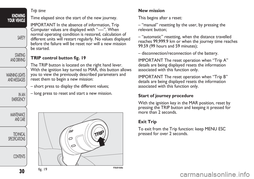
F0U018Abfig. 19
New mission
This begins after a reset:
– “manual” resetting by the user, by pressing the
relevant button;
– “automatic” resetting, when the distance travelled
reaches 99,999.9 km or when the journey time reaches
99.59 (99 hours and 59 minutes);
– disconnection/reconnection of the battery.
IMPORTANT The reset operation when “Trip A”
details are being displayed resets the information
associated with this function only.
IMPORTANT The reset operation when “Trip B”
details are being displayed resets the information
associated with this function only.
Start of journey procedure
With the ignition key in the MAR position, reset by
pressing the TRIP button and keeping it pressed for
more than 2 seconds.
Exit Trip
To exit from the Trip function: keep MENU ESC
pressed for over 2 seconds. Trip time
Time elapsed since the start of the new journey.
IMPORTANT In the absence of information, Trip
Computer values are displayed with “----”. When
normal operating condition is restored, calculation of
different units will restart regularly. No values displayed
before the failure will be reset nor will a new mission
be started.
TRIP control button fig. 19
The TRIP button is located on the right hand lever.
With the ignition key turned to MAR, this button allows
you to view the previously described parameters and
reset them to begin a new mission:
– short press to display the different values;
– long press to reset and start a new mission.
KNOWING
YOUR VEHICLE
SAFETY
STARTING
AND DRIVING
WARNING LIGHTS
AND MESSAGES
IN AN
EMERGENCY
MAINTENANCE
AND CARE
TECHNICAL
SPECIFICATIONS
CONTENTS
Page 32 of 270
31
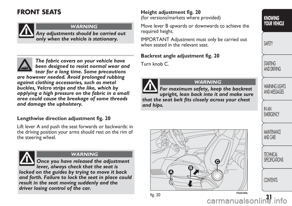
F0U019Abfig. 20
Lengthwise direction adjustment fig. 20
Lift lever A and push the seat forwards or backwards: in
the driving position your arms should rest on the rim of
the steering wheel.
Any adjustments should be carried out
only when the vehicle is stationary.
WARNING
Once you have released the adjustment
lever, always check that the seat is
locked on the guides by trying to move it back
and forth. Failure to lock the seat in place could
result in the seat moving suddenly and the
driver losing control of the car.
WARNING
The fabric covers on your vehicle have
been designed to resist normal wear and
tear for a long time. Some precautions
are however needed. Avoid prolonged rubbing
against clothing accessories, such as metal
buckles, Velcro strips and the like, which by
applying a high pressure on the fabric in a small
area could cause the breakage of some threads
and damage the upholstery.
FRONT SEATSHeight adjustment fig. 20
(for versions/markets where provided)
Move lever B upwards or downwards to achieve the
required height.
IMPORTANT Adjustment must only be carried out
when seated in the relevant seat.
Backrest angle adjustment fig. 20
Turn knob C.
KNOWING
YOUR VEHICLE
SAFETY
STARTING
AND DRIVING
WARNING LIGHTS
AND MESSAGES
IN AN
EMERGENCY
MAINTENANCE
AND CARE
TECHNICAL
SPECIFICATIONS
CONTENTS
For maximum safety, keep the backrest
upright, lean back into it and make sure
that the seat belt fits closely across your chest
and hips.
WARNING
Page 33 of 270
Always check that the seat is properly
locked on the guides by trying to push it
backwards and forwards.
WARNING
The fabric upholstery of your car is
designed to withstand normal wear and
tear for a long time. Some precautions
are however needed. Avoid prolonged rubbing
against clothing accessories, such as metal
buckles, Velcro strips and the like, which by
applying a high pressure on the fabric in a small
area could cause the breakage of some threads
and damage the upholstery.
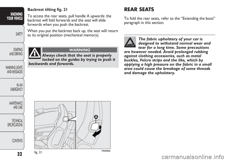
Backrest tilting fig. 21
To access the rear seats, pull handle A upwards: the
backrest will fold forwards and the seat will slide
forwards when you push the backrest.
When you put the backrest back up, the seat will return
to its original position (mechanical memory).
fig. 21F0U020Ab
32
REAR SEATS
To fold the rear seats, refer to the “Extending the boot”
paragraph in this section.
KNOWING
YOUR VEHICLE
SAFETY
STARTING
AND DRIVING
WARNING LIGHTS
AND MESSAGES
IN AN
EMERGENCY
MAINTENANCE
AND CARE
TECHNICAL
SPECIFICATIONS
CONTENTS
Page 34 of 270
33
KNOWING
YOUR VEHICLE
SAFETY
STARTING
AND DRIVING
WARNING LIGHTS
AND MESSAGES
IN AN
EMERGENCY
MAINTENANCE
AND CARE
TECHNICAL
SPECIFICATIONS
CONTENTS
The head restraints must be adjusted so
that the head, rather than the neck,
rests on them. Only in this case can they
protect your head correctly.
WARNING
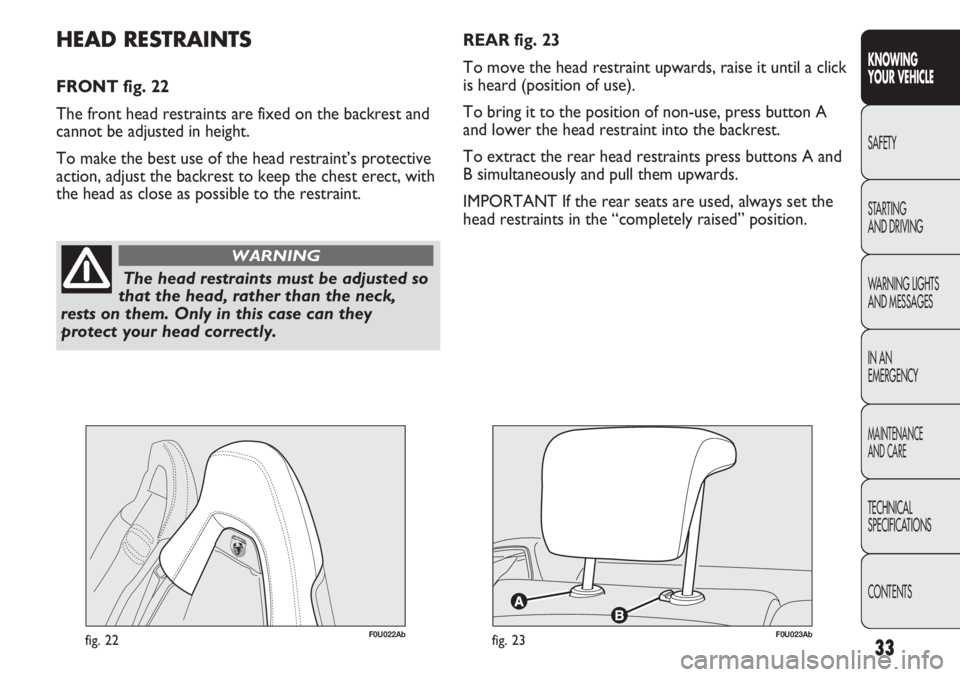
REAR fig. 23
To move the head restraint upwards, raise it until a click
is heard (position of use).
To bring it to the position of non-use, press button A
and lower the head restraint into the backrest.
To extract the rear head restraints press buttons A and
B simultaneously and pull them upwards.
IMPORTANT If the rear seats are used, always set the
head restraints in the “completely raised” position.HEAD RESTRAINTS
FRONT fig. 22
The front head restraints are fixed on the backrest and
cannot be adjusted in height.
To make the best use of the head restraint’s protective
action, adjust the backrest to keep the chest erect, with
the head as close as possible to the restraint.
fig. 22F0U022Abfig. 23F0U023Ab
Page 35 of 270
Any adjustment of the steering wheel
position must be carried out only with
the car stationary and the engine turned off.
WARNING
34
STEERING WHEEL
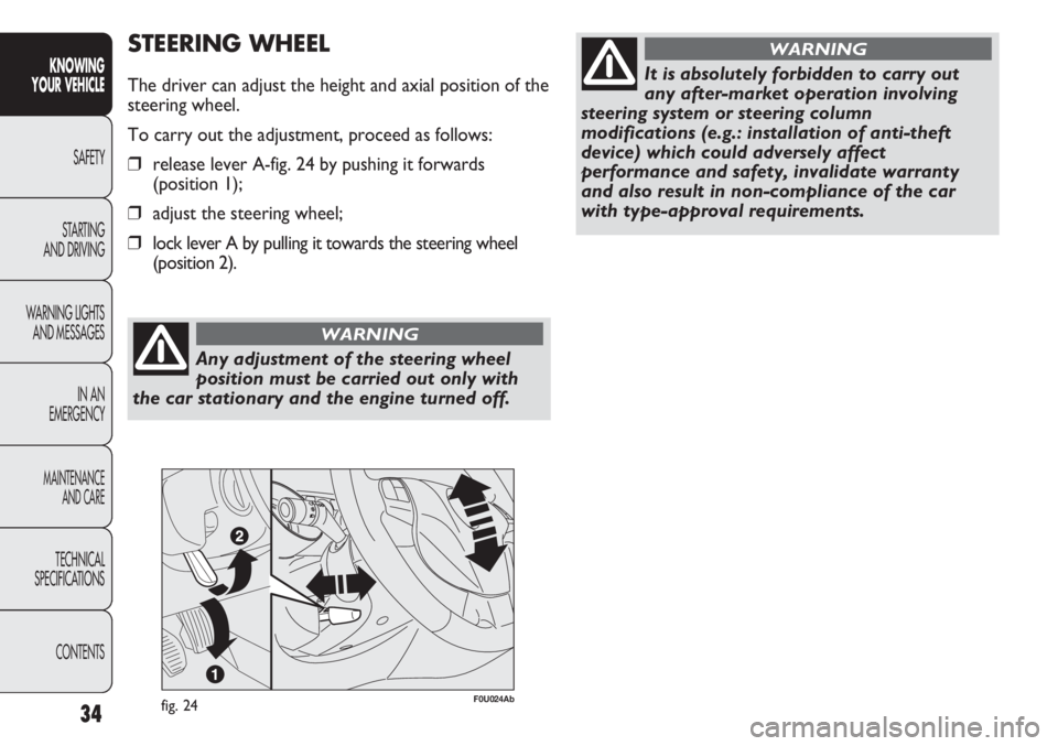
The driver can adjust the height and axial position of the
steering wheel.
To carry out the adjustment, proceed as follows:
❒release lever A-fig. 24 by pushing it forwards
(position 1);
❒adjust the steering wheel;
❒lock lever A by pulling it towards the steering wheel
(position 2).
fig. 24F0U024Ab
KNOWING
YOUR VEHICLE
SAFETY
STARTING
AND DRIVING
WARNING LIGHTS
AND MESSAGES
IN AN
EMERGENCY
MAINTENANCE
AND CARE
TECHNICAL
SPECIFICATIONS
CONTENTS
It is absolutely forbidden to carry out
any after-market operation involving
steering system or steering column
modifications (e.g.: installation of anti-theft
device) which could adversely affect
performance and safety, invalidate warranty
and also result in non-compliance of the car
with type-approval requirements.
WARNING
Page 36 of 270
35
KNOWING
YOUR VEHICLE
SAFETY
STARTING
AND DRIVING
WARNING LIGHTS
AND MESSAGES
IN AN
EMERGENCY
MAINTENANCE
AND CARE
TECHNICAL
SPECIFICATIONS
CONTENTS
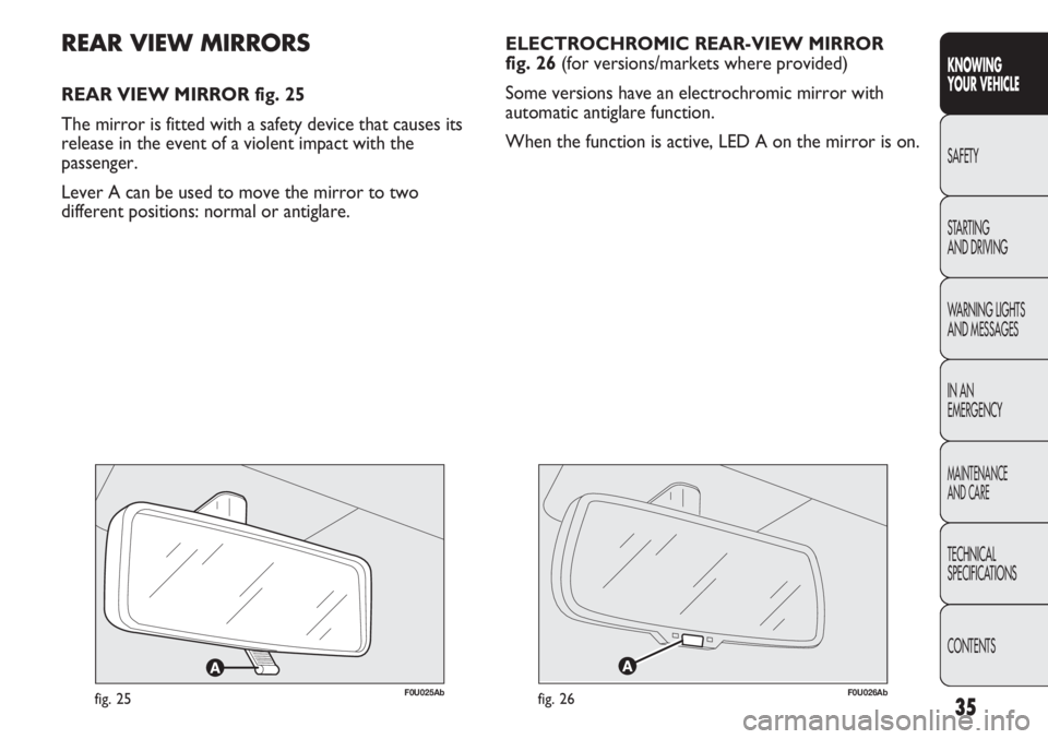
ELECTROCHROMIC REAR-VIEW MIRROR
fig. 26 (for versions/markets where provided)
Some versions have an electrochromic mirror with
automatic antiglare function.
When the function is active, LED A on the mirror is on.
F0U025Abfig. 25
REAR VIEW MIRRORS
REAR VIEW MIRROR fig. 25
The mirror is fitted with a safety device that causes its
release in the event of a violent impact with the
passenger.
Lever A can be used to move the mirror to two
different positions: normal or antiglare.
F0U026Abfig. 26
Page 37 of 270
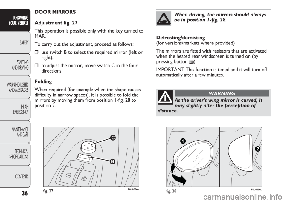
F0U027Abfig. 27
DOOR MIRRORS
Adjustment fig. 27
This operation is possible only with the key turned to
MAR.
To carry out the adjustment, proceed as follows:
❒use switch B to select the required mirror (left or
right);
❒to adjust the mirror, move switch C in the four
directions.
Folding
When required (for example when the shape causes
difficulty in narrow spaces), it is possible to fold the
mirrors by moving them from position 1-fig. 28 to
position 2.
36
KNOWING
YOUR VEHICLE
SAFETY
STARTING
AND DRIVING
WARNING LIGHTS
AND MESSAGES
IN AN
EMERGENCY
MAINTENANCE
AND CARE
TECHNICAL
SPECIFICATIONS
CONTENTS
As the driver’s wing mirror is curved, it
may slightly alter the perception of
distance.
WARNING
Defrosting/demisting
(for versions/markets where provided)
The mirrors are fitted with resistors that are activated
when the heated rear windscreen is turned on (by
pressing button
().
IMPORTANT This function is timed and it will turn off
automatically after a few minutes.
When driving, the mirrors should always
be in position 1-fig. 28.
F0U028Abfig. 28
Page 38 of 270
37
KNOWING
YOUR VEHICLE
SAFETY
STARTING
AND DRIVING
WARNING LIGHTS
AND MESSAGES
IN AN
EMERGENCY
MAINTENANCE
AND CARE
TECHNICAL
SPECIFICATIONS
CONTENTS
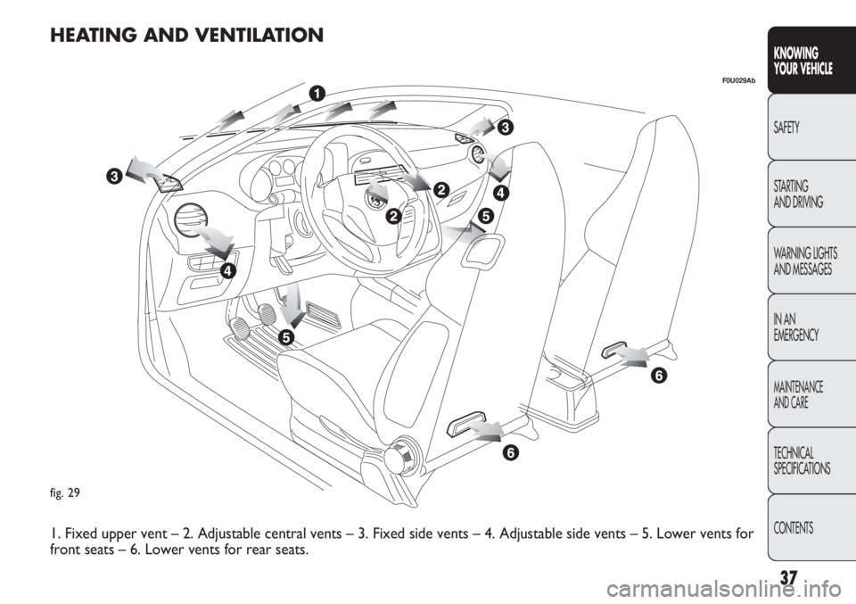
fig. 29
F0U029Ab
HEATING AND VENTILATION
1. Fixed upper vent – 2. Adjustable central vents – 3. Fixed side vents – 4. Adjustable side vents – 5. Lower vents for
front seats – 6. Lower vents for rear seats.
Page 39 of 270
38
KNOWING
YOUR VEHICLE
SAFETY
STARTING
AND DRIVING
WARNING LIGHTS
AND MESSAGES
IN AN
EMERGENCY
MAINTENANCE
AND CARE
TECHNICAL
SPECIFICATIONS
CONTENTS
F0U0030Abfig. 31
F0U032Abfig. 30F0U031Abfig. 32
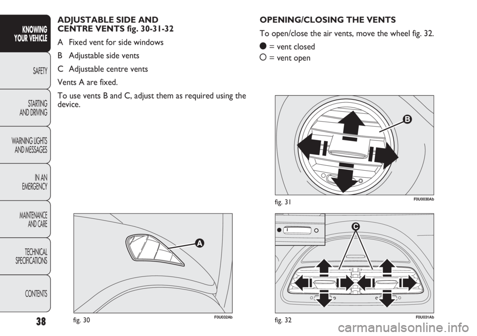
OPENING/CLOSING THE VENTS
To open/close the air vents, move the wheel fig. 32.
ç= vent closed
å= vent open ADJUSTABLE SIDE AND
CENTRE VENTS fig. 30-31-32
A Fixed vent for side windows
B Adjustable side vents
C Adjustable centre vents
Vents A are fixed.
To use vents B and C, adjust them as required using the
device.
Page 40 of 270
39
KNOWING
YOUR VEHICLE
SAFETY
STARTING
AND DRIVING
WARNING LIGHTS
AND MESSAGES
IN AN
EMERGENCY
MAINTENANCE
AND CARE
TECHNICAL
SPECIFICATIONS
CONTENTS
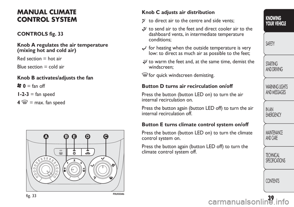
MANUAL CLIMATE
CONTROL SYSTEM
CONTROLS fig. 33
Knob A regulates the air temperature
(mixing hot and cold air)
Red section = hot air
Blue section = cold air
Knob B activates/adjusts the fan
p0= fan off
1-2-3 = fan speed
4
-= max. fan speedKnob C adjusts air distribution
¶to direct air to the centre and side vents;
ßto send air to the feet and direct cooler air to the
dashboard vents, in intermediate temperature
conditions;
©for heating when the outside temperature is very
low: to direct as much air as possible to the feet;
®to warm the feet and, at the same time, demist the
windscreen;
-for quick windscreen demisting.
Button D turns air recirculation on/off
Press the button (button LED on) to turn the air
internal recirculation on.
Press the button again (button LED off) to turn the air
internal recirculation off.
Button E turns climate control system on/off
Press the button (button LED on) to turn the climate
control system on.
Press the button again (button LED off) to turn the
climate control system off.
fig. 33F0U033Ab