Abarth Punto Evo 2012 Owner handbook (in English)
Manufacturer: ABARTH, Model Year: 2012, Model line: Punto Evo, Model: Abarth Punto Evo 2012Pages: 270, PDF Size: 3.53 MB
Page 71 of 270

INITIALISATION PROCEDURE
After the battery has been disconnected or a fuse has
blown, the operation of the sliding roof must be
initialised again.
Proceed as follows:
❒press button A-fig. 65 in closing position;
❒hold the button down so that the sunroof closes in
stages;
❒after complete closure, wait for sunroof’s electric
motor to stop.
When leaving the vehicle, always remove the key from
the ignition to avoid the risk of injury to those still
inside the car due to accidental operation of the
sunroof. Improper use of the roof can be dangerous.
Before and during operation, always check that no-one
is exposed to the risk of being injured by the moving
sunroof or by objects getting caught or hit by it.
F0U066Abfig. 66
EMERGENCY OPERATION
If the switch does not work, the sunroof can be
operated manually as follows:
❒remove the protective cap located between the two
shutters;
❒take the Allen key (provided as standard) from the
toolbox in the boot;
❒insert the key into hole A-fig. 66 and turn it:
– clockwise to open the roof;
– anticlockwise to close the roof.
70
KNOWING
YOUR VEHICLE
SAFETY
STARTING
AND DRIVING
WARNING LIGHTS
AND MESSAGES
IN AN
EMERGENCY
MAINTENANCE
AND CARE
TECHNICAL
SPECIFICATIONS
CONTENTS
Page 72 of 270

71
KNOWING
YOUR VEHICLE
SAFETY
STARTING
AND DRIVING
WARNING LIGHTS
AND MESSAGES
IN AN
EMERGENCY
MAINTENANCE
AND CARE
TECHNICAL
SPECIFICATIONS
CONTENTS
DOORS
DOOR CENTRAL LOCKING/UNLOCKING
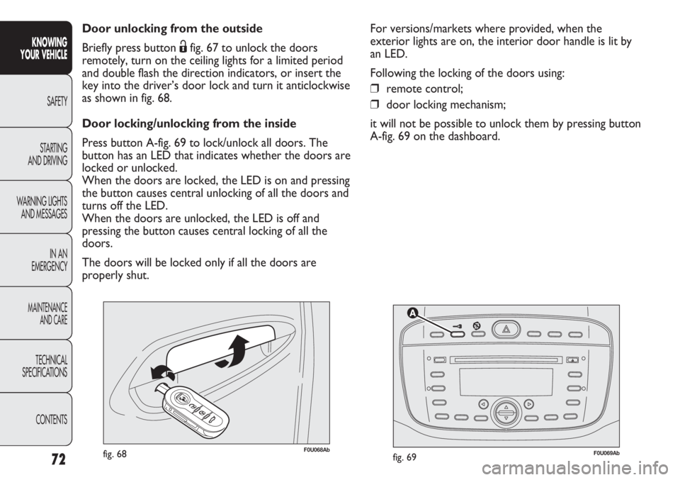
Locking from the outside
With the doors closed, press button Áon the remote
control fig. 67 or insert the key into the lock of the door
on the driver’s side and turn it clockwise fig. 68. The
locking of the doors is signalled by the LED on button
A-fig. 69 flashing once. The doors can be locked only if
they are all shut. If one or more doors are open after
pressing button Áon the remote control fig. 67, the
direction indicators and the LED on the button A-fig. 69
flash quickly for approximately 3 seconds.
F0U067Abfig. 67
If one or more doors are open after turning the key,
only the LED on button A-fig. 69 will blink rapidly for
approximately three seconds. If the doors are closed but
the boot is open, the doors are locked: the direction
indicators (only when locking is carried out using button
Áfig. 67) and the LED on button A-fig. 69 flash quickly
for approximately 3 seconds.
With this function on, you can still unlock the other
doors by pressing button A-fig. 69 on the central control
panel.
Double-tapping button Áon the remote control fig. 67
activates the dead lock device (see “Dead lock”).
Page 73 of 270

72
KNOWING
YOUR VEHICLE
SAFETY
STARTING
AND DRIVING
WARNING LIGHTS
AND MESSAGES
IN AN
EMERGENCY
MAINTENANCE
AND CARE
TECHNICAL
SPECIFICATIONS
CONTENTS
F0U069Abfig. 69F0U068Abfig. 68
Door unlocking from the outside
Briefly press button Ëfig. 67 to unlock the doors
remotely, turn on the ceiling lights for a limited period
and double flash the direction indicators, or insert the
key into the driver’s door lock and turn it anticlockwise
as shown in fig. 68.
Door locking/unlocking from the inside
Press button A-fig. 69 to lock/unlock all doors. The
button has an LED that indicates whether the doors are
locked or unlocked.
When the doors are locked, the LED is on and pressing
the button causes central unlocking of all the doors and
turns off the LED.
When the doors are unlocked, the LED is off and
pressing the button causes central locking of all the
doors.
The doors will be locked only if all the doors are
properly shut.For versions/markets where provided, when the
exterior lights are on, the interior door handle is lit by
an LED.
Following the locking of the doors using:
❒remote control;
❒door locking mechanism;
it will not be possible to unlock them by pressing button
A-fig. 69 on the dashboard.
Page 74 of 270

73
KNOWING
YOUR VEHICLE
SAFETY
STARTING
AND DRIVING
WARNING LIGHTS
AND MESSAGES
IN AN
EMERGENCY
MAINTENANCE
AND CARE
TECHNICAL
SPECIFICATIONS
CONTENTS
IMPORTANT With central locking on, pulling the
internal handle of one of the front doors will unlock that
door. Individual doors can be unlocked by pulling the
opening handle of one of the rear doors.
If a power supply is not present (blown fuse, battery
disconnected, etc.) it is, however, possible to lock the
doors manually.
After exceeding 20 km/h, all the doors will be locked
automatically if the setup menu function has been
selected (see “Reconfigurable multifunction display”
paragraph in this section).
Once the dead lock system is engaged, it
is impossible to open the doors from
inside the vehicle. Before getting out of the car,
please therefore check that there is no-one left
inside. If the remote control battery is flat, the
system can only be disengaged by using the key
metal insert in either of the door locks.
WARNING
DEAD LOCK
(for versions/markets where provided)
This safety device inhibits the operation of:
❒internal handles;
❒locking/unlocking button A-fig. 69;
thereby preventing the opening of the doors from inside
the passenger compartment if there has been a break-in
attempt (e.g. a window has been broken).
The dead lock device therefore offers the best possible
protection against break in attempts. We recommend
engaging it whenever the vehicle is parked and left
unattended.
Page 75 of 270

Device activation
The dead lock device is automatically activated on every
door when pressing the remote control button Ábriefly
twice, fig. 67.
Device activation is indicated by 3 flashes of the
direction indicators and the flashing of the LED in
button A – fig. 69 located in the dashboard controls.
If one or both doors are not closed correctly, the dead
lock device will not activate, thus preventing a person
from getting stuck inside the passenger compartment by
entering the car through, and then closing, the open
door.
Device deactivation
The system is disabled automatically on every door
when:
❒opening the driver’s door using the mechanical key;
❒unlocking doors using the remote control;
❒turning the ignition key to the MAR position.
74
KNOWING
YOUR VEHICLE
SAFETY
STARTING
AND DRIVING
WARNING LIGHTS
AND MESSAGES
IN AN
EMERGENCY
MAINTENANCE
AND CARE
TECHNICAL
SPECIFICATIONS
CONTENTS
F0U072Abfig. 70
POWER WINDOWS
Two switches fig. 70 on the inner armrest of the
driver’s door control the following with the ignition key
in the MAR position:
A opening/closing the left front window
B right front window opening/closing
Continuous automatic operation
The driver’s front window is equipped with an
automatic device for winding the window up and down.
Page 76 of 270

75
KNOWING
YOUR VEHICLE
SAFETY
STARTING
AND DRIVING
WARNING LIGHTS
AND MESSAGES
IN AN
EMERGENCY
MAINTENANCE
AND CARE
TECHNICAL
SPECIFICATIONS
CONTENTS
F0U073Abfig. 71
Keep the button pressed for longer than half a
secondto operate the automatic continuous winding of
the window. The window will stop when it is fully
opened or closed, or when the button is pressed again.
IMPORTANT With the ignition key at STOP or
removed, the electric windows remain activated for
about two minutes and are deactivated as soon as a
door is opened.
Passenger side door
The front passenger door armrest features switch A-
fig. 71 for controlling the corresponding window.
Incorrect use of the power windows may
be dangerous. Before and during
operation, always check that no-one is exposed
to the risk of being injured either directly by the
moving window or through objects getting
caught or by being hit. When leaving the
vehicle, always remove the key from the ignition
to avoid the risk of injury to anyone remaining
in the car due to accidental operation of the
electric windows.
WARNING
Page 77 of 270

76
KNOWING
YOUR VEHICLE
SAFETY
STARTING
AND DRIVING
WARNING LIGHTS
AND MESSAGES
IN AN
EMERGENCY
MAINTENANCE
AND CARE
TECHNICAL
SPECIFICATIONS
CONTENTS
F0U074Abfig. 72F0U075Abfig. 73
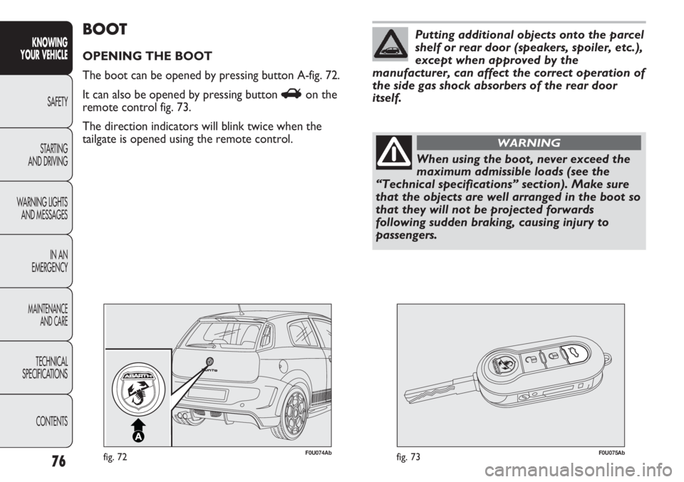
BOOT
OPENING THE BOOT
The boot can be opened by pressing button A-fig. 72.
It can also be opened by pressing button Ron the
remote control fig. 73.
The direction indicators will blink twice when the
tailgate is opened using the remote control.
When using the boot, never exceed the
maximum admissible loads (see the
“Technical specifications” section). Make sure
that the objects are well arranged in the boot so
that they will not be projected forwards
following sudden braking, causing injury to
passengers.
WARNING
Putting additional objects onto the parcel
shelf or rear door (speakers, spoiler, etc.),
except when approved by the
manufacturer, can affect the correct operation of
the side gas shock absorbers of the rear door
itself.
Page 78 of 270

77
KNOWING
YOUR VEHICLE
SAFETY
STARTING
AND DRIVING
WARNING LIGHTS
AND MESSAGES
IN AN
EMERGENCY
MAINTENANCE
AND CARE
TECHNICAL
SPECIFICATIONS
CONTENTS
When travelling, do not put any object
on the parcel shelf because they can
injure passengers in the event of an accident or
sudden braking.
WARNING
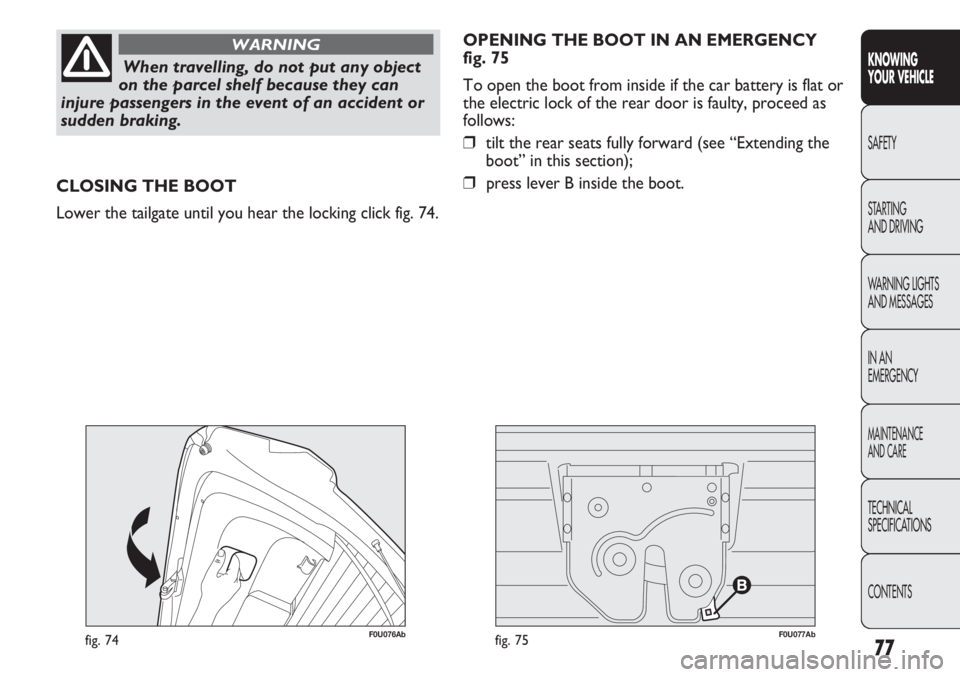
F0U076Abfig. 74
CLOSING THE BOOT
Lower the tailgate until you hear the locking click fig. 74.OPENING THE BOOT IN AN EMERGENCY
fig. 75
To open the boot from inside if the car battery is flat or
the electric lock of the rear door is faulty, proceed as
follows:
❒tilt the rear seats fully forward (see “Extending the
boot” in this section);
❒press lever B inside the boot.
F0U077Abfig. 75
Page 79 of 270

78
KNOWING
YOUR VEHICLE
SAFETY
STARTING
AND DRIVING
WARNING LIGHTS
AND MESSAGES
IN AN
EMERGENCY
MAINTENANCE
AND CARE
TECHNICAL
SPECIFICATIONS
CONTENTS
F0U078Abfig. 76
EXTENDING THE BOOT
Tilting the rear seat forwards gives maximum loading
volume.
Proceed as follows:
❒fully lower the rear seat head restraints;
❒check that the seat belts are not twisted;
F0U079Abfig. 77
F0U081Abfig. 78
❒tilt the cushions forward as shown by the arrow
fig. 76;
❒operate the handles A and B-fig. 77 to release the
backrests and guide them down onto the cushion.
Page 80 of 270

79
KNOWING
YOUR VEHICLE
SAFETY
STARTING
AND DRIVING
WARNING LIGHTS
AND MESSAGES
IN AN
EMERGENCY
MAINTENANCE
AND CARE
TECHNICAL
SPECIFICATIONS
CONTENTS
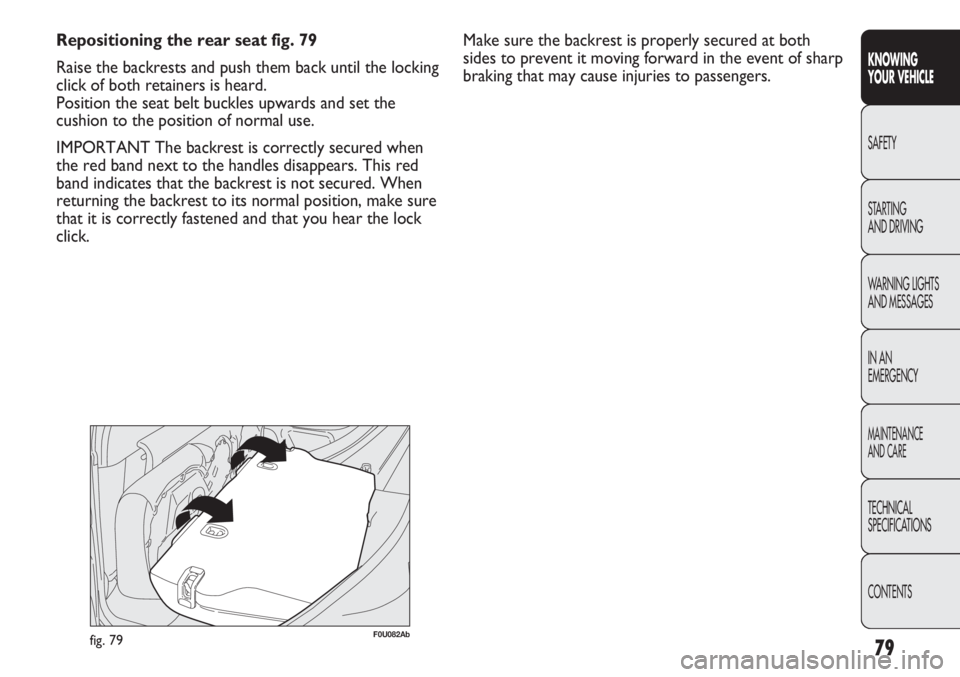
Repositioning the rear seat fig. 79
Raise the backrests and push them back until the locking
click of both retainers is heard.
Position the seat belt buckles upwards and set the
cushion to the position of normal use.
IMPORTANT The backrest is correctly secured when
the red band next to the handles disappears. This red
band indicates that the backrest is not secured. When
returning the backrest to its normal position, make sure
that it is correctly fastened and that you hear the lock
click.
F0U082Abfig. 79
Make sure the backrest is properly secured at both
sides to prevent it moving forward in the event of sharp
braking that may cause injuries to passengers.