ACURA INTEGRA 1994 Service Repair Manual
INTEGRA 1994
ACURA
ACURA
https://www.carmanualsonline.info/img/32/56982/w960_56982-0.png
ACURA INTEGRA 1994 Service Repair Manual
Trending: height adjustment, sensor, check engine, battery location, height, air filter, fog light bulb
Page 271 of 1413
ldle Control System
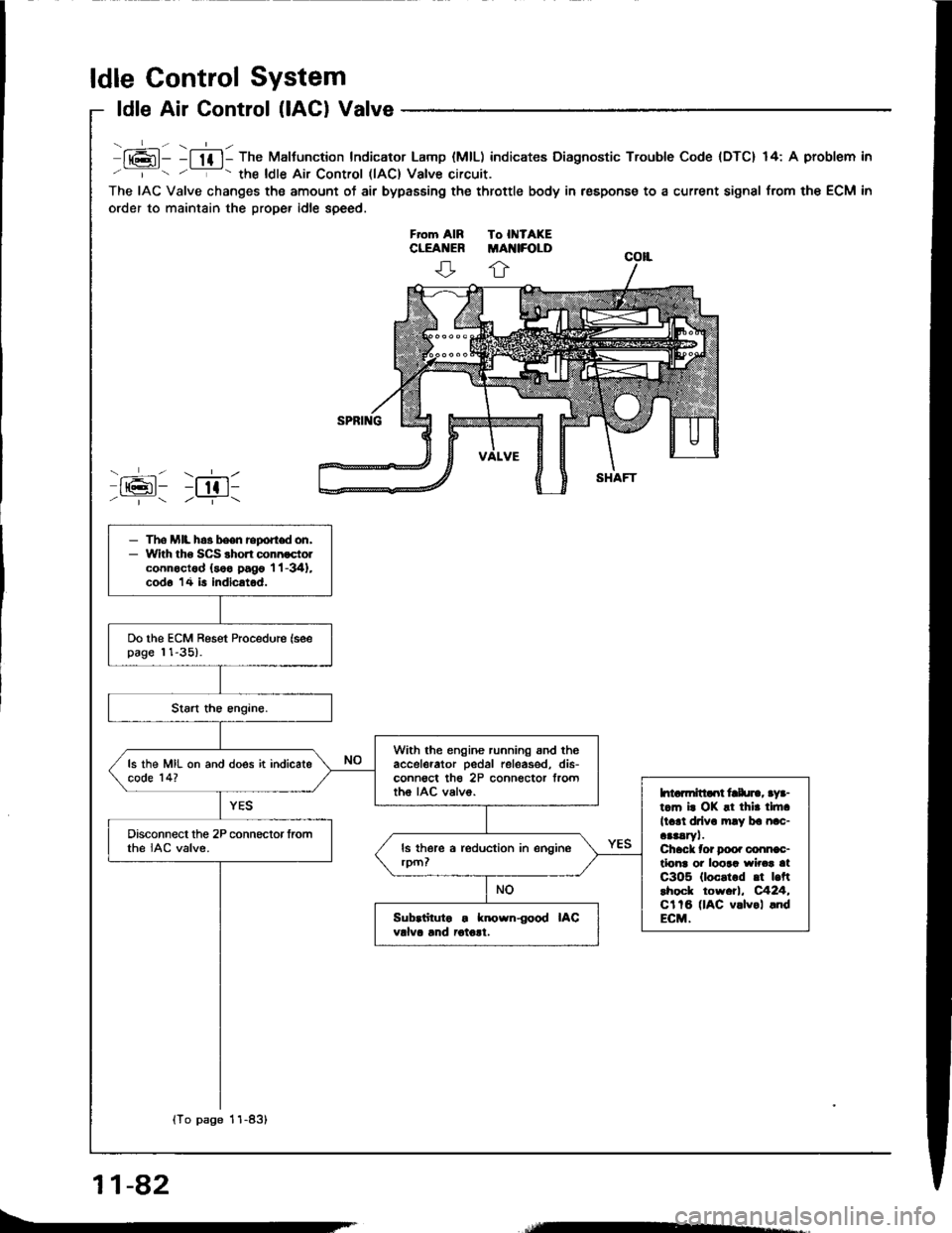
ldle Air Control (lACl Valve
lt6l- -l lf l- The Maltunction Indicator Lamp (MlL) indicates Diagnostic Trouble Code {DTC} 14: A problem in
' '- the ldle Air Control llAC) Valve circuit.
The IAC Valve changes the amount of air bypasEing the throttle body in respons€ to a current signal from the ECM in
order to maintain the proper idle speed.
ffi: r;611/ | /--T-\
- The MIL h.3 been report don,- With tho SCS shon connoctolconnoctod (soo pago 'l 'l -341,
cod6 14 is indicatod.
Do the ECM Reset Procedure (seepage 11-35).
With the engine running snd theaccelerator pedal releas€d, dis-conn€ct th€ 2P connector frorttho IAC valvo.
ls the MIL on and does it indicatecode 14?
htarmitlaot frlu]., aya-t.m i. OK !t thir tlft.
ll.rl drlv. mly ba nac-aaaaryl.Chack tor Doo. conn€c-tlonr oi loora wirca atC3O5 (loc.t.d .t |.ftlhock tow.tl, C424,Cl tB (lAC v.lvol .ndECM.
Disconnect the 2P connector fromthe IAC valve.
Sub.iituto . known{ood IACvdva lnd iotolt.
{To page 11-83}
11-82
Page 272 of 1413
(From page 'l 1-82)
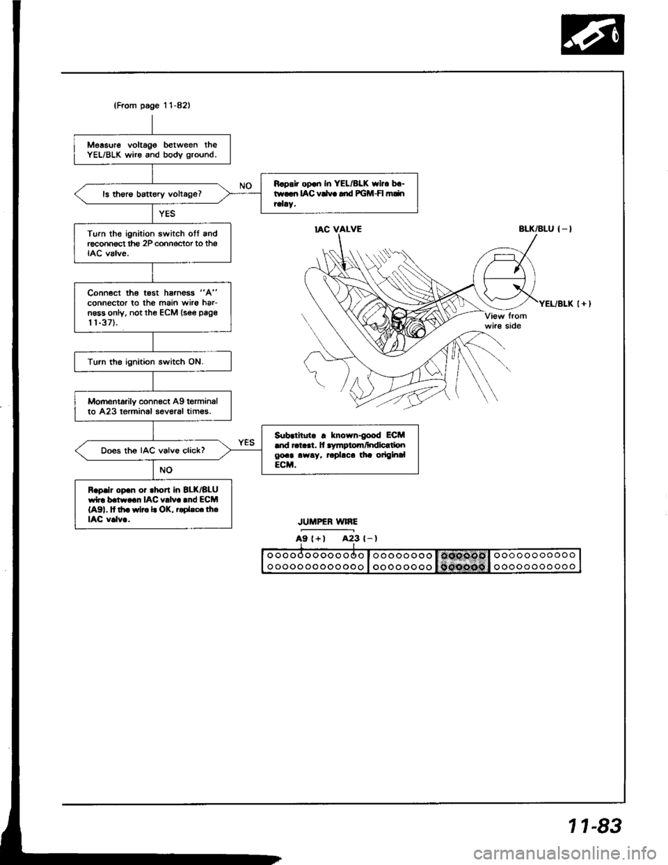
Measure voltago between theYEL/BLK wire and bodv ground.
R.pair op.n In YEL/8LK who b.-twoon IAC vCvc dd PGM-FI mdnrelay.ls th€rs battery voltage?
Turn th€ ignition swirch ott andreconnect thg 2P cohnector to theIAC valve.
Conn€ct the test hs.ness "A"
connector to the main wirs hrr-n6ss only, not the ECM lsee page
t 1-37).
Tu.n tho ignition switch ON.
Momentarily connect Ag torminalto 423 terminol seveaal tim€s.
Sub.titutr ! known{ood ECM.nd ral..t. lt .ymptom/hdlcatioogoa! awsy. rophca tia origlnalECM.
Does th6 IAC valve click?
Raplir op.n or rhort in 8LK/BLUwl]. b.tw.cn IAC v!lv..nd ECM(A91, It th. wlro L OK, r.Dhc.lheIAC v.lv..
IAC VALVEBLK/BLU { _ }
JUMPER WIRE
A9 l+) A23 {-l
1 1-83
Page 273 of 1413
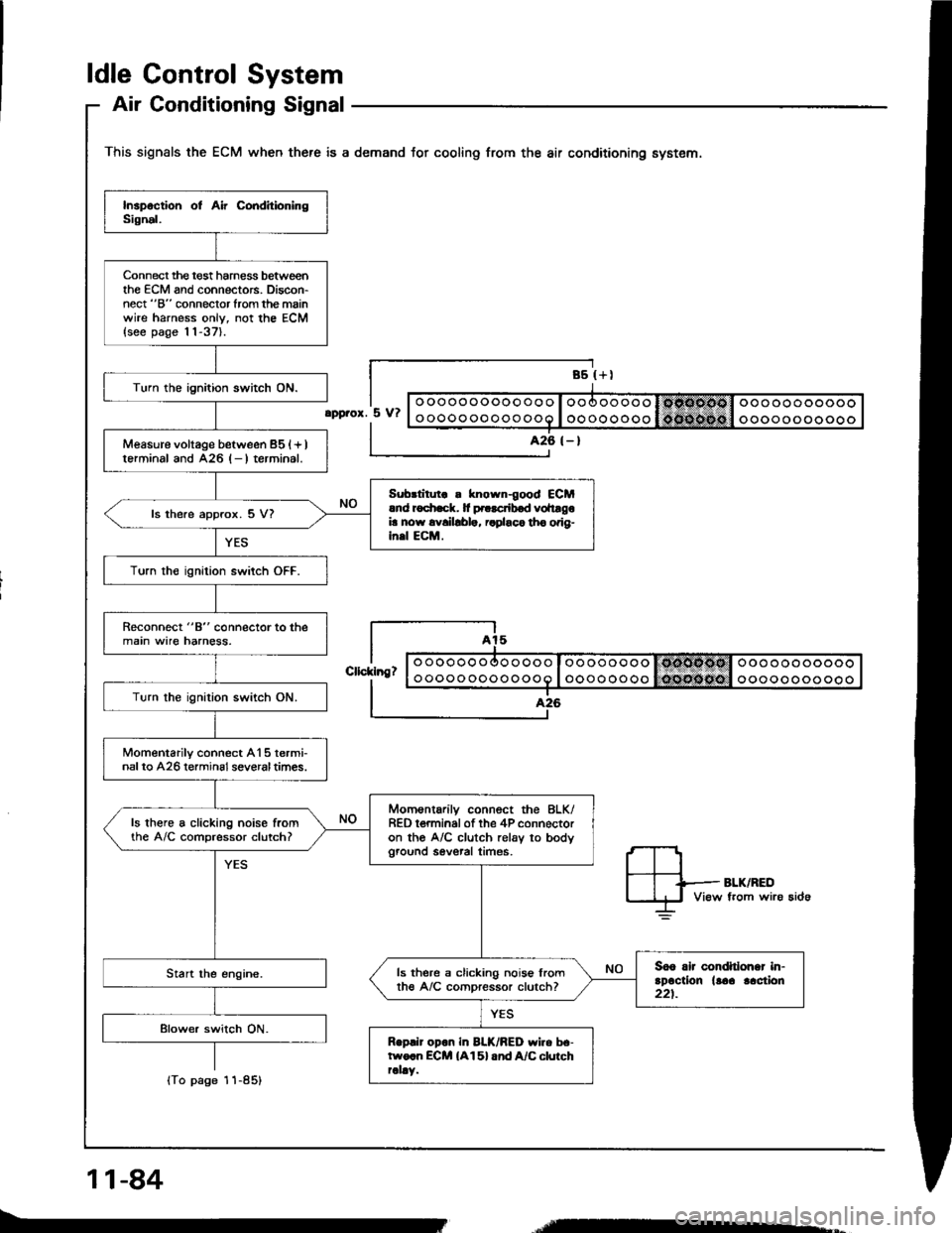
ldle Gontrol System
Air Conditioning Signal
This signals the ECM when there is a demand for cooling from the air conditioning system.
Connect the t€st harness betweenthe ECM and connectors. Discon-nect "B" connector from the mainwire harness onlv, not the ECM{see page 11-37}.
Turn the ignition switch ON.
Measure voltage between 851+ )lerminal and A26 l- I terrninal.
Sub.litut ! known{ood €CMrnd r6
ls there approx. 5 V?
Turn th€ ignition switch OFF.
Reconnect "8" connector to themain wire harness.
Turn the ignilion switch ON.
Momentarilv connect A15 termi-nalto A26 terminsl severaltimes.
Momsntarilv connect the 8LK/RED t€rminal of the 4P connectoron the A/C clutch rel6v to bodyground sevsral times.
ls there a clicking noise fromthe A/C comDressor clutch?
3o6 rlr condhlohar in-rDactlon llaa lac{ion221.
ls there a clicking nois€ lromth€ A/C comoressor clutch?
Rop.ir opon in BLK/BED wiro be-two.n ECM {A15} and A/C clurchrally.
ooooooooooooo
oooooooooooo
oooooooo
oooooooo
ooooooooooo
ooooooooooo
.pprox. 5 V?
426 (- )
Cllcklng?
lTo page
11-84
-
Page 274 of 1413
(From page 11-84)
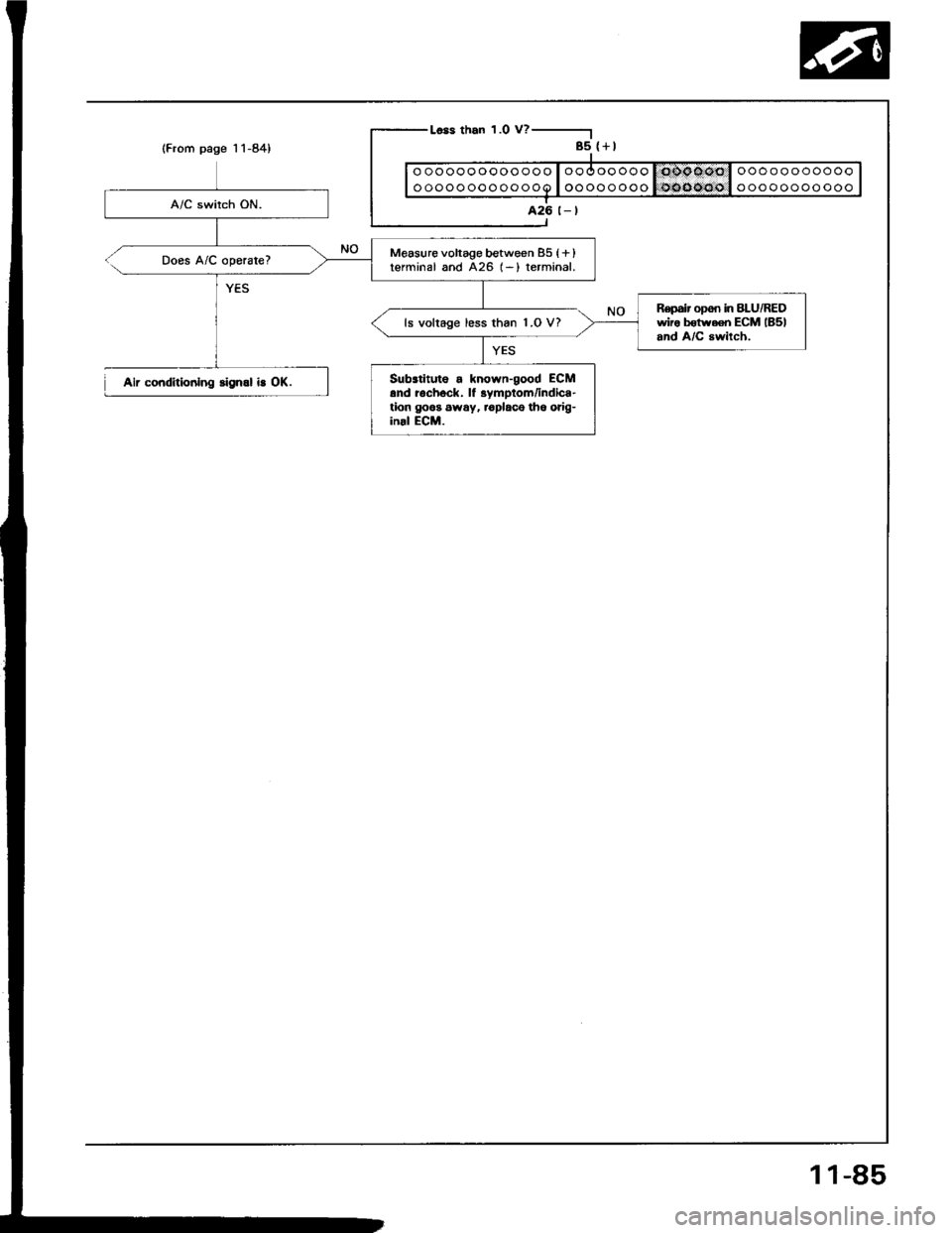
Does A/C operate?
Aii coiditiodlng slgnal i! OK.
r-Less than 1.0 V? -----------.1
I 85 {+l
|----------------I| | ooooooooooooe loooooooo 1t)6i}66i)l ooooooooooo Il-_---_-------l-I 426 t_t
Measure voltage between 85 {+ )terminal and A26 (-) terminal.
R€pair opoi in BLU/REDwiro b€trYaen ECM lBSland A/C awilch.ls voltage less than 1.O V?
Substituto a known-good ECMand rochock, lf 3ymptom/indica-tion goos 6way, r€placo th6 orig-inal ECM.
11-85
Page 275 of 1413
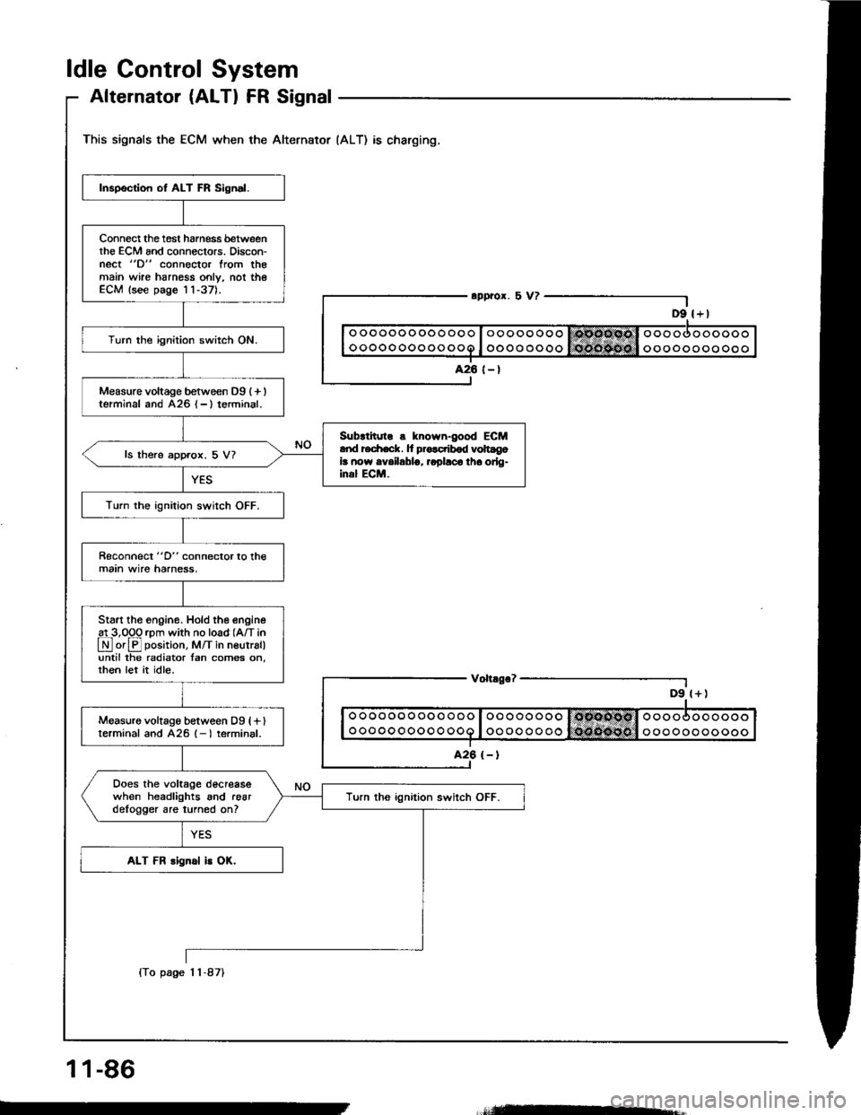
ldle Control System
Alternator (ALTI FR Signal
This signals the ECM when the Alternator (ALT) as charging.
D9 l+)
Inspection ot ALT FR Sign.l.
Connect the tost harness betweenthe ECM and connectors. Discon-nect "D" connector from themain wire harnoss only, not theECM lsee page 11-37).
Turn the ignition switch ON.
Measure voltage between D9 (+ )terminal and A26 {-}terminal.
Sub{inno s known-good ECMand redrack. It pro.ctibod volt gola now availablg, ropllco tha orlg-inal ECM.
ls there approx. 5 V?
Turn the ignition switch OFF.
Reconnect "D" connector to themain wire harness,
Start tho engino. Hold the engine
!L3,099 rpm with no load (A/T in
LN] or El position, M/T in neutral)until the radiator tan comes on,rhen let it idle.
Measuro voltage between Dg (fl
terminal and 426 (- I terminal.
Does the voltage decreasewhen headlights and .eardelogger are turned on?Turn ths ignition switch OFF.
ALT FR rignal is OK.
o oo oo o ooooo
ooooooooooo
Voh.go?
ooooooooooo
ooooooooooo
1 1-86
(To page 1 1-87)
=-
Page 276 of 1413
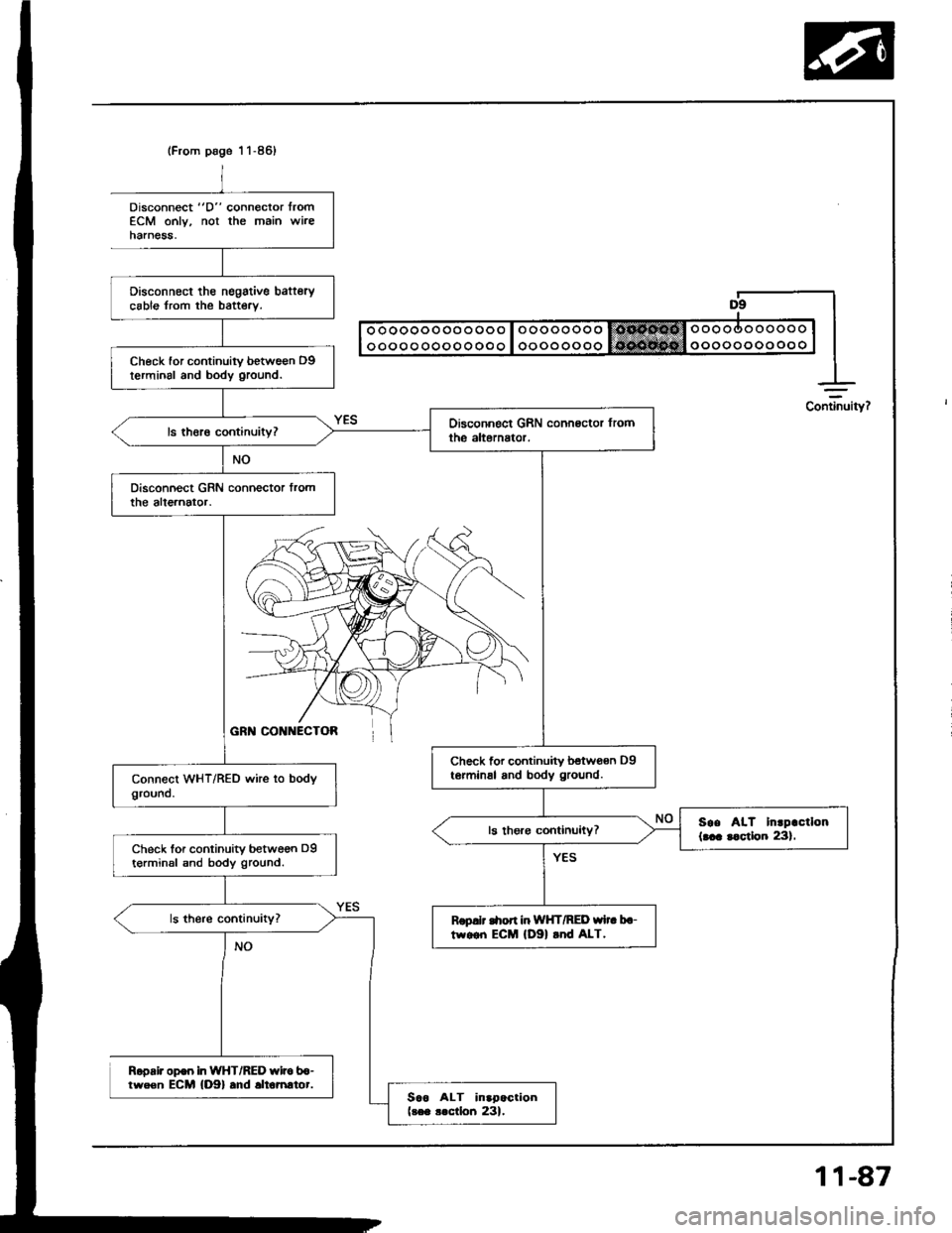
(From page 1 1-86)
Disconnect tho nsgstive bafterycable from the baftery.
Check for continuity betwe€n D9terminal and body ground.
Check for continuity betwoan D9te.minal and body ground.
soe AIT Inrpactlon(... r.ctlon 231.Check lor continuity between D9t€rminsl snd body ground.
Rop.lt C|on in WHT/RED wi.. b.-tw.on ECM lDgl rnd ALT.
Sao ALT inapactionlres .lctlon 231.
Disconnect "D" connector lromECM only, not the main wireharnesa,
Ropair op€o in WHT/RED wito b6-tween ECM {D9} .nd .ltomrtor.
Continuity?
11-87
Page 277 of 1413
ldle Control System
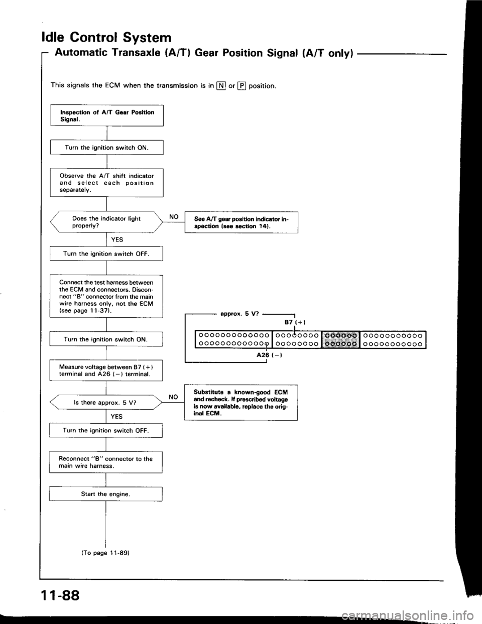
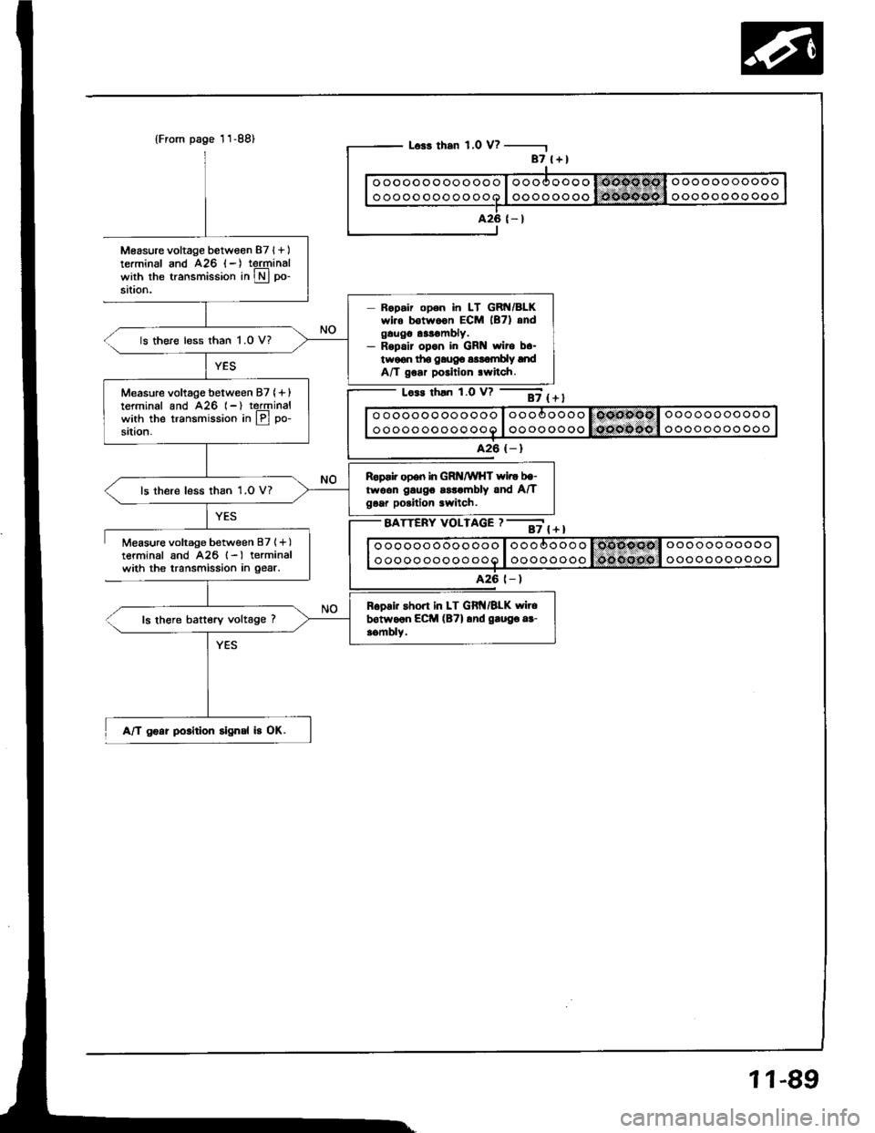
Automatic Transaxle {A/Tl Gear Position Signal {A/T onlyl
This signals the ECM when the transmission is in @ or @ position.
appror. 5 V?
1 1-88
-.
87 l+)
ooooooooooooo
oooooooooooo
A26 {-}
Turn the ignition switch ON.
obsorve the A/T shift indicatorand s eiecl each positionseparately.
Soo A/T goa. position indicator in-spoqtion ls6o lection 141.
Turn the ignition switch OFF.
Connect the test hamess betweenthe ECM and connectors. Discon-nect "B" connoclorlrom the mainwire harness only, not the ECM(see page 11-37).
Turn the ignition switch ON.
Measure voltage between 87 (+ Iterminal and 426 1- ) terminal.
Subslituto . known-good ECM6nd .ech6ck. lf pr63cribod voltageia now availablo, rcplaco ths o.ig-inel ECM.
ls there approx. 5 V?
Turn the ignition switch OFF.
Reconnect "8" connector lo lhemaan wire harness.
(To page 11-89)
Page 278 of 1413
Measure voltage between 87l+)terminal and A26 (-) teJqrinalwith the transmission in Lryl po-
sataon.
Measure voltage between B7l+)terminal and A26 l-) terminalwith the transmission in gear.
{From page 11-88)
A/T goat position signal b OK.
L63r than 1,0 V? -
Lo.s rhln 1.0 v? --ii t + t
o oooooo oooooo I oooooooo I OOnPsOl oooooo ooooo
ooooo ooooo ooo I oooooooo lQcosito I ooooooooooo
A26 (- )
BATTERY VOLTAGE ? --;; { + I
87 l+)
ooooooooooooo
oooooooooooo
426 (- )
Ropair open in LT GRN/BLKwir. botwoon ECM lB7) andgaugo as!€mbly.- Rspalr opon in GR wito b.-twoon tho gaug6 a$ombly lndA/T goar position .witch.
ls there less than 1.0 V?
Measure voltage between 87 (+ Iterminal and A26 (-) reJqrinalwith the transmission in lPl po-
sition.
Reprir open in GRNMHT wi.r bg-twoon gaugo ssrombly and A/Tgoar poritlon 3witch.ls there less than 1.0 V?
R6oai. short in LT Git{/BLK wirebotwo6n ECM (B7l and gaugo ar-aombly.ls there battery voltage ?
A26 t- )
11-89
Page 279 of 1413
ldle ControlSystem
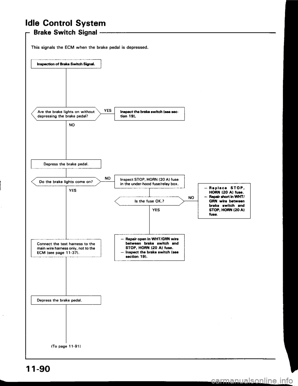
Brake SwitchSignal
This signals the ECM when the brake pedal is depressed.
11-90
Inlp.ction ot Brd(. Switcfi Siignal.
Are the brake lights on withoutdepressinO the brake pedal?ltuoacl ths braka .wilch {!.a !ac-don 191,
Inspect STOP, HORN (20 Allusein the undeFhood fuse/relav box.Oo the brake lights come on?
R.pl!c. STO P,HOR {2O A) tu...R.pdr dbrt In WtlT/GBI wlrr batu..nb?!ka .wltch a.rdsToP, HOR[{ (20 A}lura.
ls the luse OK.?
- Ropalr opon In WHT/GRN wirobatwoan b'lka lwltch andSTOP, HORTI {20 Al lu!o.- InlDect tho braka awitch la6a.6cdon 19).
Connect tho t€st harness to themain wire hamess only, not to theECM {see page 11-37).
(To page 'l1-91)
Page 280 of 1413
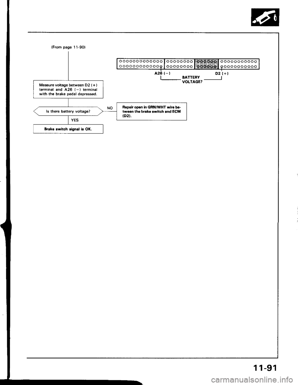
(From page 11-9Ol
426 {-)
I-- BATTERYVOLTAGE?
D2 (+l
Measurc vohage between D2 (+ lterminal and A25 (-) terminalwith the brake oedal deoressed.
Repair opon in GRI{/WHT wiro bo-twoen th6 b..ko rwitch .nd ECM{D2}.
Brako lwitch signal ir OK,
1 1-91
Trending: catalytic converter, oil type, transmission oil, change wheel, child seat, ad blue, oil temperature

