ACURA INTEGRA 1998 Service Repair Manual
INTEGRA 1998
ACURA
ACURA
https://www.carmanualsonline.info/img/32/56983/w960_56983-0.png
ACURA INTEGRA 1998 Service Repair Manual
Trending: fuse, steering, overheating, battery capacity, wiper fluid, air conditioning, mirror controls
Page 1171 of 1680
)
t
J
Altelnator ttelr Inspecuon ano Aol
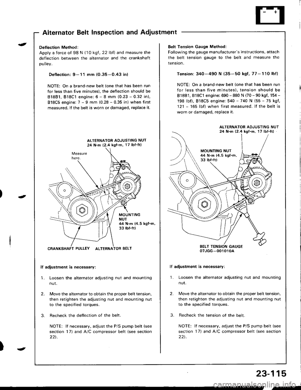
Detlection Method:
Apply a force ol 98 N (1 0 ksl, 22 lbl) and measure the
deflection between the alternator and the crankshaft
DUllev,
Defloction: 9- 11 mm (O.35-O.43 inl
NOTE: On a brand-new belt (one that has been run
for less than five minutes), the deflection should be
81881, Bl8Cl engine: 6 - 8 mm (0.23 - 0.32 inl,
818C5 engine: 7 - I mm (0.28 - 0.35 in) when first
measured, lf the belt is worn or damaged, replace it.
ALTERNATOR ADJUSTING NUT
24 N.m 12,4 kgl.m, 17 lbI'ftl
MOUNTINGNUT44 N.m (4.5 kgf.m,33 tbf.ft)
CRANKSHAFT PULLEY ALTERNATOR BELT
lf adiustment is necessary:
1. Loosen the alternator adjusting nut and mounting
nut.
2.
3.
Move the alternator to obtain the proper belt tension,
then retighten the adiusting nut and mounting nut
to the specified torques.
Recheck the dellection of the belt.
NOTE: lI necessary, adjust the P/S pump belt (see
section 17) and A/C compressor belt (see section
221.
Belt Tension Gauge Method:
Following the gauge manulacturer's instructions, attach
the belt tension gauge to the belt and measure the
tension.
Tension: 340-490 N {35-50 kgf,77-11O lbf)
NOTE: On a brand-new belt (one that has been run
for less than five minutes), tension should be
818B1, 818C1 engine: 690 - 880 N (70 - 90 kgf, 154 -
198 lbf), 818C5 engine: 540 - 740 N (55 - 75 kgf,
121 - 165 lbf) when first measured. lf the belt is
worn or damaged, replace it.
lf adiustment is necessary:
1. Loosen the alternator adjusting nut and mounting
nut.
2.
3.
Move the alternator to obtain the proper belt tension,
then retighten the adjusting nut and mounting nut
to the specified torques.
Recheck the tension ot the belt.
NOTE: It necessary, adjust the P/S pump belt (see
section 17) and A/C compressor belt (see section
22t.
ALTERNATOR ADJUSTING NUT24 N.m 12.4 kgf'm, 17 lbt.ftJ
BELT TENSION GAUGEoTJGG -0010r0A
23-115
J
,-
Page 1172 of 1680
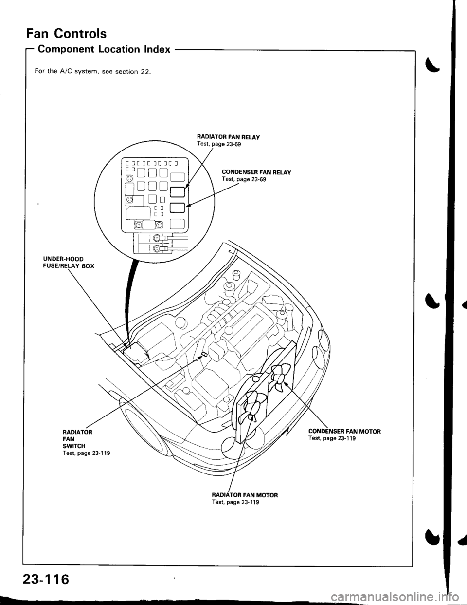
Fan Controls
RADIATORFANswtTcHTest, page 23-119
Component Location Index
For the A/C system, see section 22.
UNDER-HOODFUSE/RELAY BOX
CONDENSER FAN RELAYTest, page 23-69
RADIATOR FAN RELAYTest, page 23,69
FAN MOTORTest, page 23-119
TOR FAN MOTORTest, page 23,119
: lt tt tt tt l
c=, Ll L-t t lf l]-]l
f1 a l f -r a'r -
I i I r""""rlla-t fr -
a tL) | |Irt -
1/^ l/-\ltr.z{ N/ L
Page 1173 of 1680
Circuit Diagram (Without A/Cl
UNOEF.OASHFUSE,NELAY BOX
|-;ffi;I-YELf\-.rl]-t
BTK'EL -l
RAOIATORFANS\,YITCHfoN : above )(199'F (93'C)J
BLIVREO
BLK
I
G201G401
IGNITION SWITCH
N0.41 (lmAl No.42 (104)
RADIATORFANRELAY
23-117
.l
Page 1174 of 1680
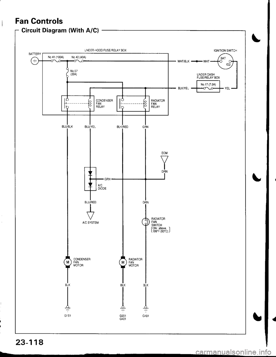
Fan Controls
IGN TION SWITCH
/ BAI \WHT/ELK +-WHTT rcotr
UNDER DASH
-
IFUSE/8ELAY 8ox I
|-;;;l IBL(rYEL t==rYEL-l
BLUiYEL
I
I
I
.h
Ith*-'T'o'oo'
8LU/RED
+A/C SYSTEM
.,'l'**u.'
UNDER.HOOD FUSEi NELAY BOX
No 41 (100A) No 42 (40A)
23-114
Page 1175 of 1680
)
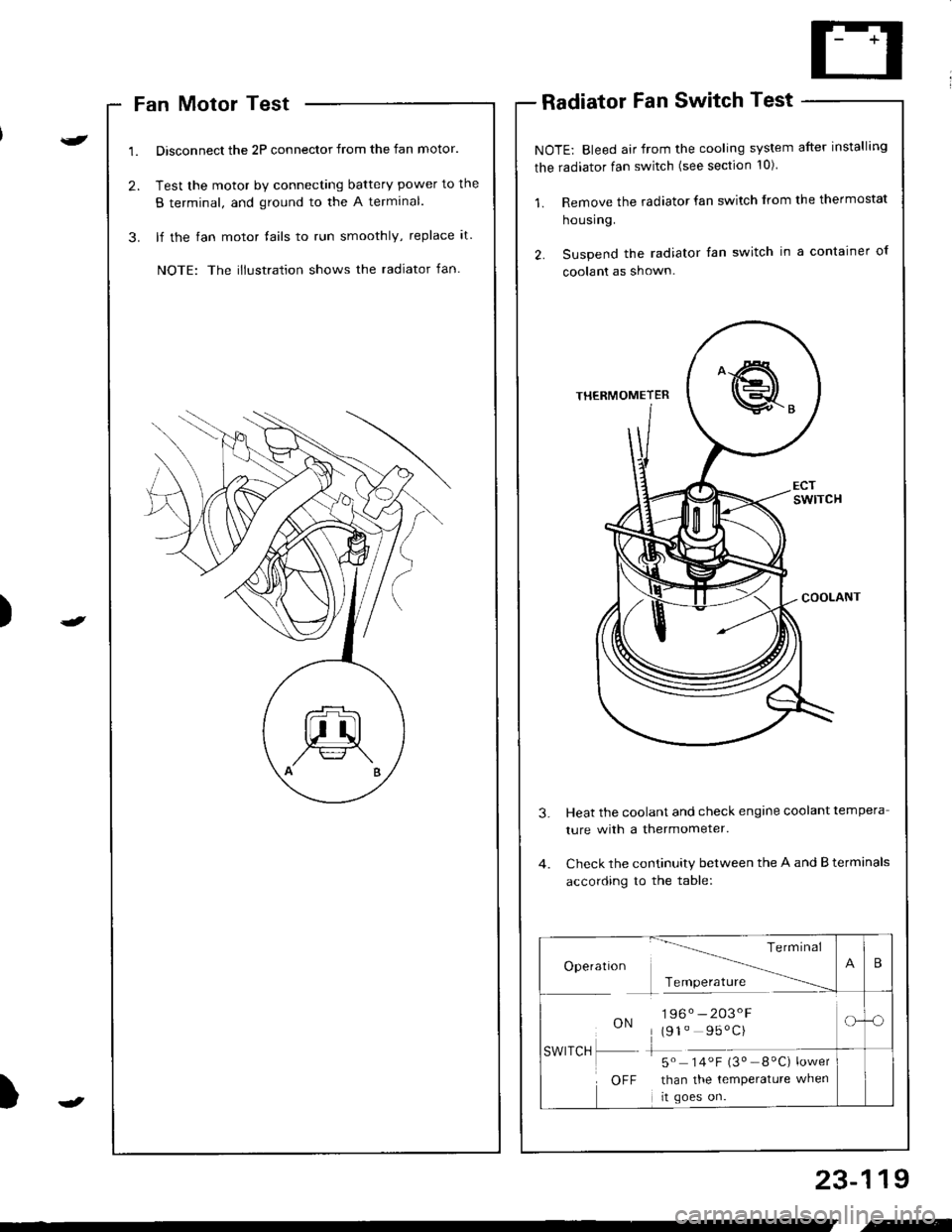
Fan Motor Test
Disconnect the 2P connector from the fan motor.
Test the motor by connecting battery power to the
B terminal, and ground to the A termlnal.
lf the fan motor fails to run smoothly, replace it.
NOTE: The illustration shows the radiator fan.
Radiator Fan Switch Test
NOTE: Bleed air from the cooling system after installing
the radiator fan switch (see section 10)
1. Remove the radiator fan switch from the thermostat
housing.
2. Suspend the radiator fan switch in a container ol
coolanl as shown.
Heat the coolant and check engine coolant tempera
ture with a thermometer.
Check the continuity between the A and B terminals
according to the table:
23-119
Te rm Inal
Operatlon -------\
Tcmoerature ------
ON196. -203'F
(91" 95'C)
-5" 14.F i3" _8"C) ;*,*
than the temperature when
rt goes on.
SWITCH
OFF
B
-o
.-
Page 1176 of 1680
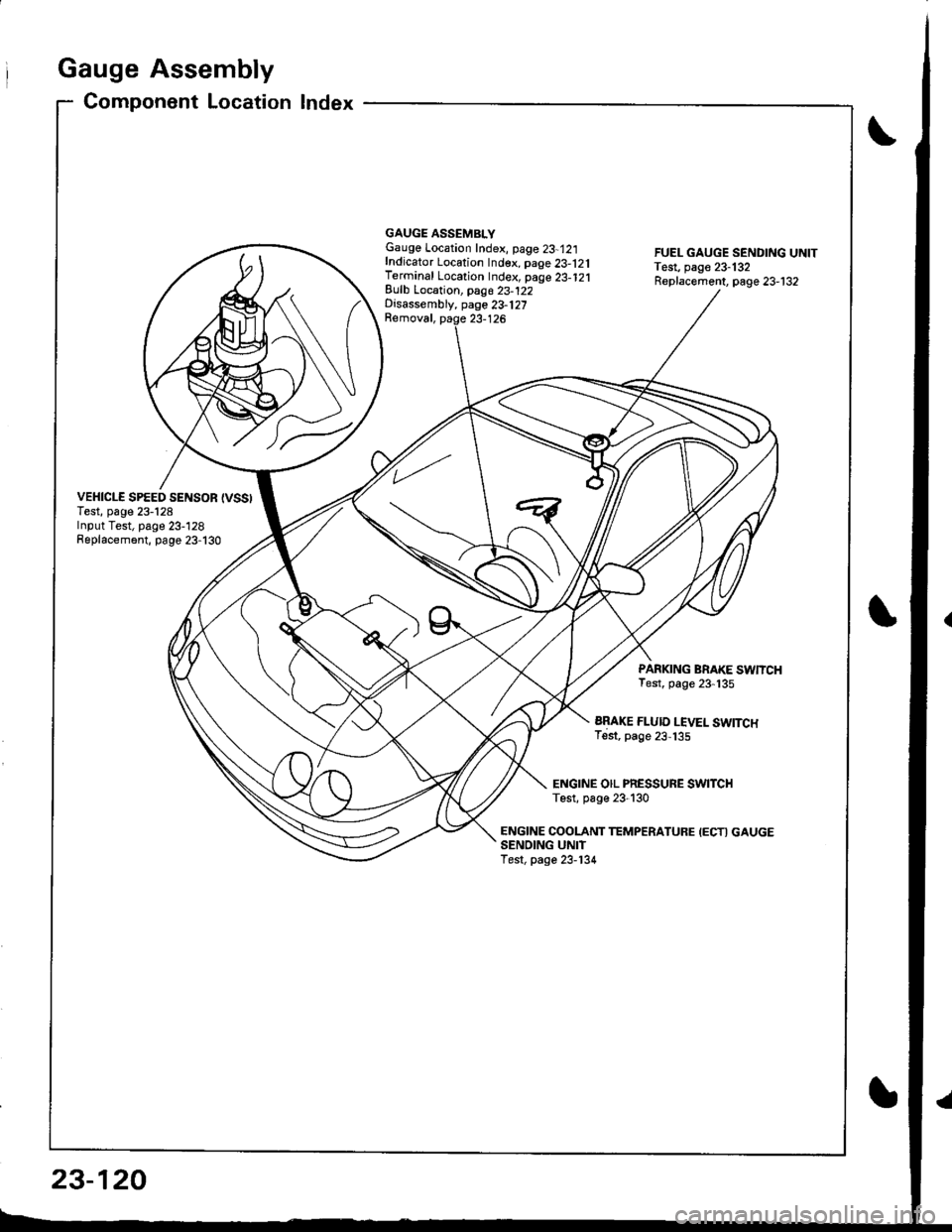
Gauge Assembly
Component Location Index
VEHICLE SPEED SENSOR {VSSITest, page 23-128Input Test, page 23-128Replacement, page 23-130
GAUGE ASSEMBLYGauge Location Index, page 23-12:|fndicator Location Index. page 23-121Terminal Location Index, page 23-121Eulb Location, pag6 23-122Disassembly, page 23-127Removal, paqe 23-126
FUEL GAUGE SENDING UNITTest, page 23-132Replacement, page 23-132
PARKING BRAKE SWNCHTest, page 23-135
ARAKE FLUID LEVEL SWITCHTest, page 23,135
ENGINE OIL PRESSURE SWITCHTest, p6ge 23-130
ENGINE COOLANT TEMPERATUFE IECTI GAUGESENOING UNITTest, page 23-134
23-120
Page 1177 of 1680
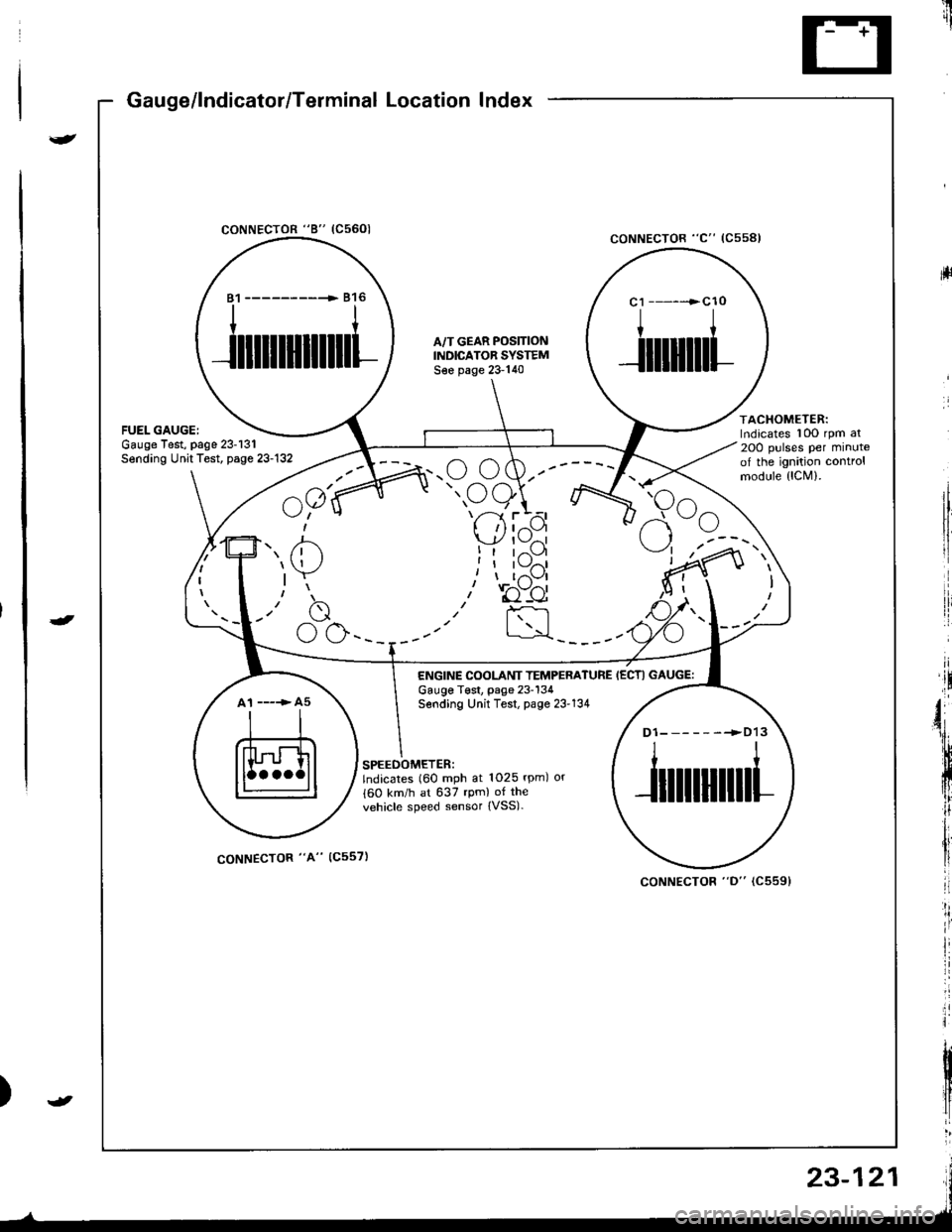
Gauge/lndicator/Terminal Location Index
coNNECTOR "8" (C5601
ltrii
rll
coNNECTOR "C" (Css8l
ACHOMETER:rdicates 10O rpm al
OO pulses per minutef the ignition controlrodule {lCM).
81 ------------ 816
ililllllilll
A,/T GEAR POS]TIONINDICATOR SYSTEMS€e page 23-140
c1 ------>cl0
I
Jilliltl
atespage 23-131t Test, page 23-132
^a1(
u;" u
7' /'- /n.u (,w.--
" oe)\r- -7 ttt'-1 r --
I 'l I z{.-a\y' | \-./^l
!t tr--',9I I l\-//11, I t,-\Jl
.r' to"-ei
I :rl
F<
elrle
ENGINE COOLANT TEMPERATUREGauge T€st, page 23-134Sending Unit Test, page 23'134
IECTI GAUGE:
A1 ----> A5
D1-------->D13
ililtl|illl
SPEEOOMETER:lndicates (60 mph at 1025 rpm) or
{60 km/h at 637 rpm) of the
vehicle speed sensor {VSS).
coNNECTOR "A" (C557)
coNNECTOR "D" (C5591
23-121
Page 1178 of 1680
I
rIGauge Assembly
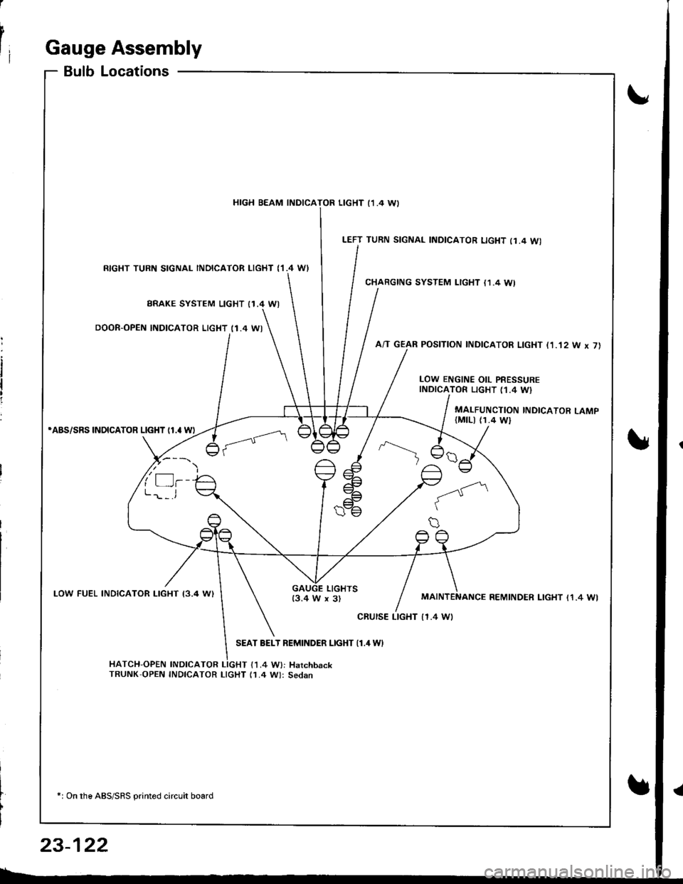
BulbLocations
RIGHT TURN SIGNAL INOICATOR LIGHT ('I.4 WI
BRAKE SYSTEM LIGHT I1.4 WI
DOOR-OPEN INDICATOR LIGHT (1.4 WI
*ABS/SRS INOICATOR LIGHT (1.' W)
LOW FUEL INDICATOR I-IGHT I3.4 W)
SEAT BELT REMINDER LIGHT {1.4 WI
HATCH-OPEN INDICATOR LIGHT {1.4 W}: HarchbackTRUNK'OPEN INDICATOR LIcHT (1.4 W): Sedan
+: On the ABS/SRS printed circuit board
LEFT TURN SIGNAL INDICATOR LIGHT (1.4 WI
CHARGING SYSTEM LIGHT {1,4 WI
A/T GEAR POSITION INDICATOR LIGHT (1.'t2 W x 7)
HIGH BEAM INDICATOR LIGHT I1 .4 \A,
LOW ENGINE OIL PRESSUREINDICATOR LIGHT (1.4 W}
MALFUNCTION INDICATOR LAMP(MtLl (1.4 Wl
LIGHTS13.4 W x 3)REMINDER LIGHT I1.4 WI
cRursE LTGHT | 1.4 Wt
23-122
Page 1179 of 1680
UNDER.DASHFUSE/RELAY 8OX
No.l5 (7.54)
No 2s (7 5A)
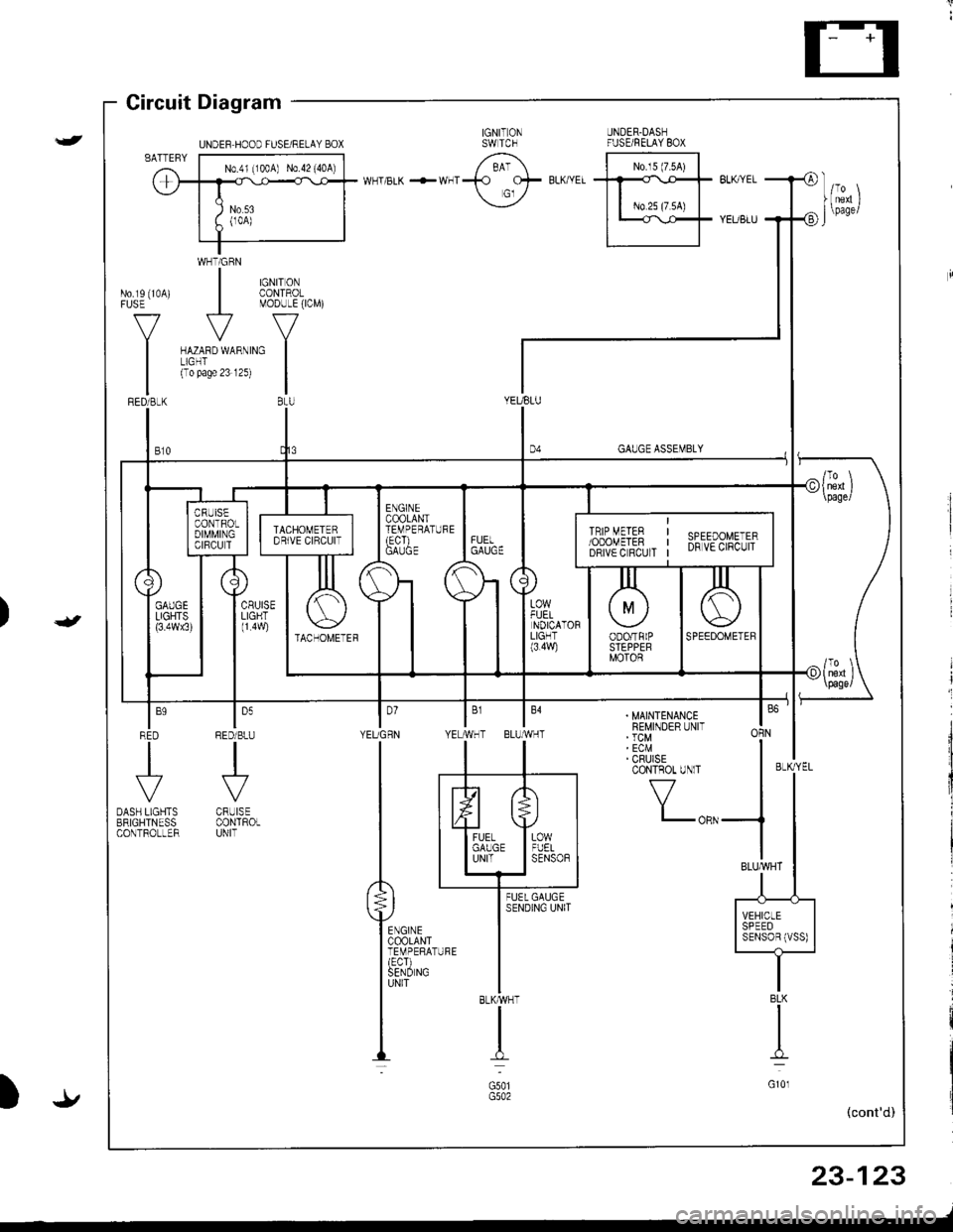
Gircuit Diagram
WHTiGRN
| $il,�4,
V
MODULE(ICM)
ru{no unrno I(To pase 23 12s)
|BtU
No.rs (10A)FUSE
V
I
GAUGE ASSEMBLY
YEUBLU
t,,
| ,,J,,
1l
|;;il'-II SPEED II SENSoBIVSS) |-t-
. MAINTENANCEREMINDER UNIT' TCM' ECM' CRUISECONTROT UNlT
f7
I-oRN
BLKMHT
I
G501
I'YEUGRN YE
ln
tl
P**,,,'
ffirxl-"
louRED/BLU
.J'-
CRUISECONTROLUNIT
BLK
I
G10l
23-123
-/
UNDEF HOOD FUSE/RELAY BOX
Page 1180 of 1680
auge Assembly
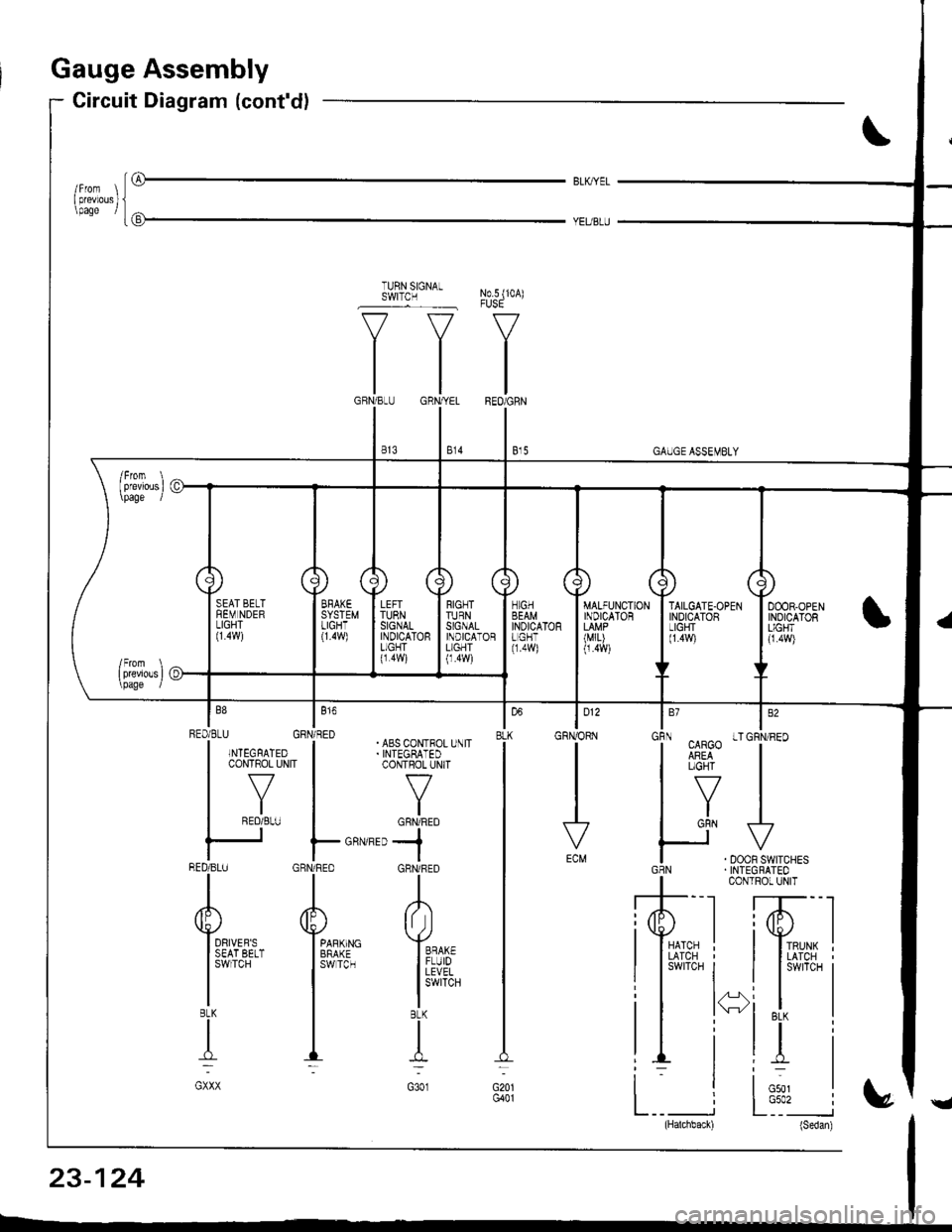
Circuit Diagram (cont'dl
iG
BLK,IYEL
No.5 (10A)
V
IREO/GRN
I e,s
TURN SIGNALSWITCN
v--=v
tltl
tlGBN/BLIJ GRN,YEL
lltl
I e's I s,o
"i.uv"'T""
H^,J.**.GBN . INTEGRATEO
I coNrRor uNrT
,'T--l ffi--l
lI*ni lI*i
il i*i t i
i. li;, I
L__ i L:'�_" i(Hatchback) (Sedan)
| 012
GRNORN
vECM
louBLK
G20lG401
RIGNTTURNSIGNALINDICATORL]GHT(1.4w)
TAILGATE.OPENINDICATORLIGHT(1.4!9
RED/BLU GBN/RED| | . ABS CoN-FOL U\lTI .NTEGFATED I .INTEGBATED
|
*v^"
|
-'v*
| .roL-" I or*frro
ts Fo.''-,,-jBED/BLU GRN/RED GHNi RED
rrl
AAA
Yu'**- Y*,,r" Y**
l3$i;.?.'' 13ffi3- ll#,
| | l!i,Iib'.
TIT:-_:
GXXX G3O1
23-124
Trending: height, display, brown, jump cable, oil capacity, cruise control, tow bar

![ACURA INTEGRA 1998 Service Repair Manual Circuit Diagram (Without A/Cl
UNOEF.OASHFUSE,NELAY BOX
|-;ffi;I-YELf\-.rl]-t
BTKEL -l
RAOIATORFANS\,YITCHfoN : above )(199F (93C)J
BLIVREO
BLK
I
G201G401
IGNITION SWITCH
N0.41 (lmAl No.42 (104)
RAD ACURA INTEGRA 1998 Service Repair Manual Circuit Diagram (Without A/Cl
UNOEF.OASHFUSE,NELAY BOX
|-;ffi;I-YELf\-.rl]-t
BTKEL -l
RAOIATORFANS\,YITCHfoN : above )(199F (93C)J
BLIVREO
BLK
I
G201G401
IGNITION SWITCH
N0.41 (lmAl No.42 (104)
RAD](/img/32/56983/w960_56983-1172.png)
