electrical ACURA INTEGRA 1998 Service Repair Manual
[x] Cancel search | Manufacturer: ACURA, Model Year: 1998, Model line: INTEGRA, Model: ACURA INTEGRA 1998Pages: 1680, PDF Size: 53.14 MB
Page 205 of 1680
i
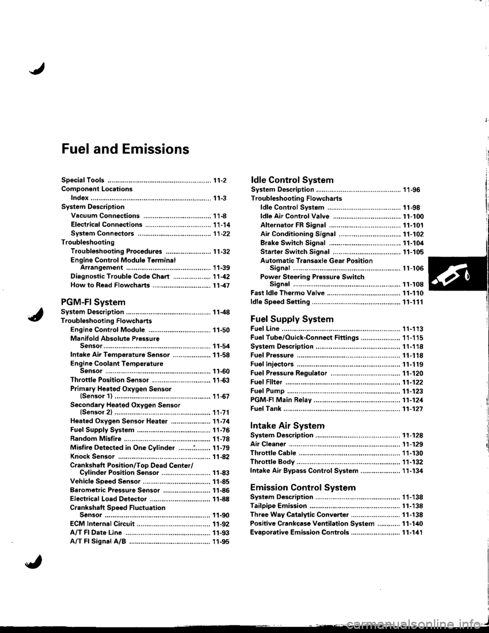
iFuel and Emissions
SDeciaf Toofs ..,...,...............11-2
Component Locations
Index.,..,.,..................................,.,.,.,.,.,..,.,....... 11-3
System Description
Vacuum Connections ..................................,. 11-8
Electrical Connections ................................... 1 1-14
System Connectors ....,.,.,.,............................ 1 1-22
Troubleshooting
Troubfeshooting Procedures ........................ 11.32
Engine Control Module T€rminalArrangement .,.,.,..,.,. 11-39
Diagnostic Trouble Cods Chart .......-.-.......... 11-42
Howto Read Flowcharts ......,..,.,................... 1147
PGM-Fl System
System Description ............ 11-4
Troubleshooting Flowcharts
Engine Control Module ............,...,..,.,........... 11-50
Manifold Absolute PressureSensor...............................,..,.,...,................ 11-54
Intake Air TemDerature Sensor ..........,...,..... 11-58
Engine Coolant TemperatureSensor ....................,.,...,.,........................... 11-60
Throttle Position Sensor .,...........................,. 11-63
Primary Heated Oxygen Sensor(Sensor'l) .......,......,.,. 11-67
Secondary Heated Oxygen Sensorlsensor 2) .................. 11-71
Heated Oxygen Sensor Heater .....................'t1.74
Fuel Supply System ....................................... 1 1-76
Random Mistire ............. 11-78
Misfire Detected in One Cylinder .....,..:,,.,.... 11-79
Knock Sensor .........,.,..,. f -A2
Crankshaft Position/Top Dead Center/Cylinder Position Sensor .,........................ 11-83
Vehicle Speed Sensor .............,.,.,.,....,........... 11-85
Barometric Prsssute Sensor ..,...................... 11-86
Electrical Load Detector ...................,.,.......... 11-88
Crankshaft SDeed FluctuationSensor ...........................................,...,........ 11-90
ECM lnternal Circuit,..............................-......, 11-92
A/T Fl Date Line ............ 11-93
A/T Fl Signal A/B .......... 11-95
I,-1
Page 207 of 1680
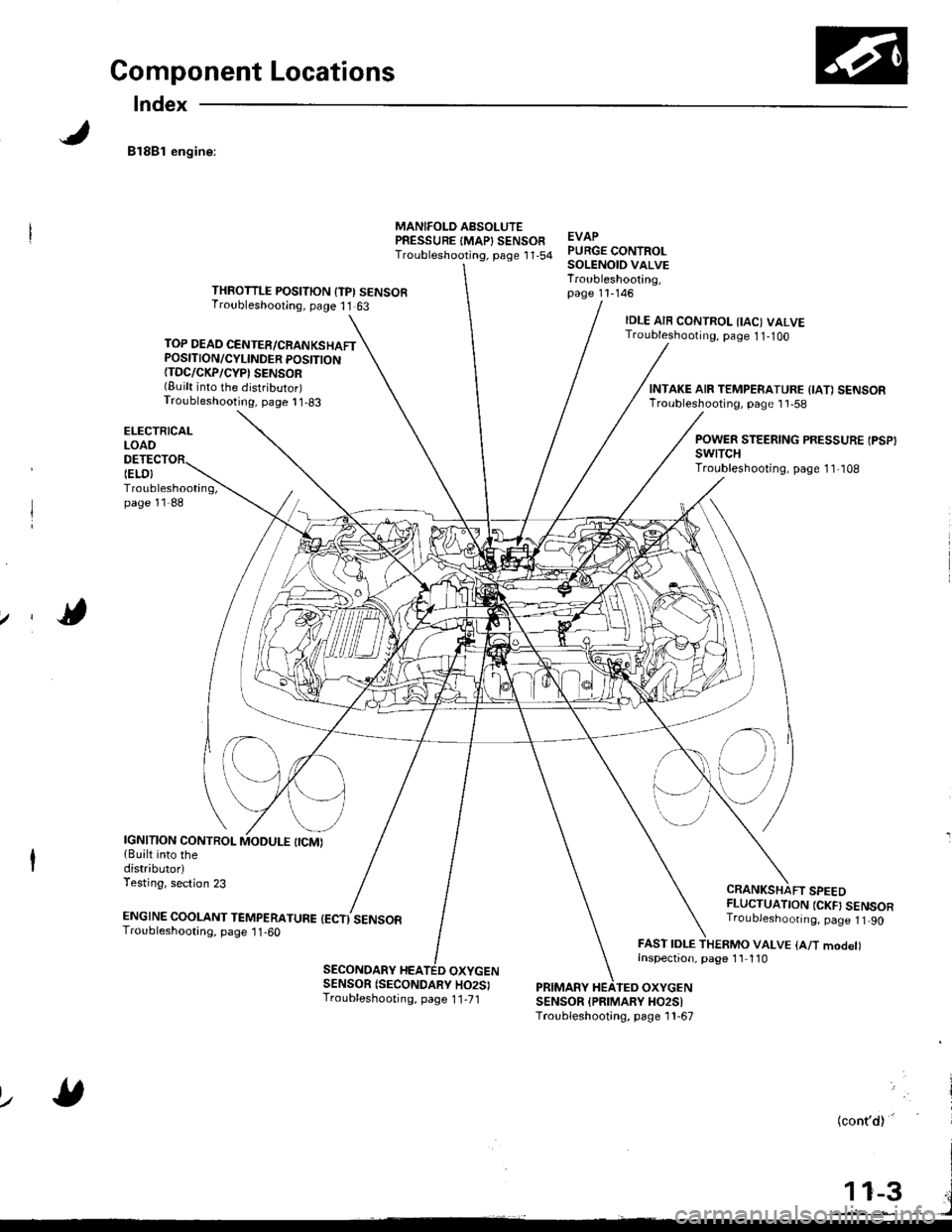
Component Locations
Index
81881 engine:
TOP DEAD CENTER/CRANKSHAFTPOSITION/CYLINDER POSITION{TDC/CKP/CYP' SENSOR(Built into the distributor)Troubleshooting, page I 1-83
ELECTRICALLOAO
Troubleshooting,page 11-88
MANIFOLD AsSOLUTEPRESSURE IMAP} SENSOFTroubleshooting, psge 1 '1,54EVAPPURGE CONTROLSOLENOID VALVETroubleshooting,page 11-146THROTTLE POSITION {TPI SENSORTroubleshooting, page 11 63
IELO}
IDLE AIR CONTROL IIAC) VALVETroubleshooting, page 1 1-1OO
CRANKSHAFT SPEEDFLUCTUATION {CKF} SENSORTroubJeshoonng. page 1t 90
FAST IDLE THERMO VALVE {A/T modet)Inspection, page 1'l 110
INTAKE AIR TEMPERATURE {IA1 SENSORTroubleshooting, page 1 'l -58
POWER STEERING PRESSURE IPSP}swtTcHTroubleshooting, page 1 1,108
IGNITION CONTROL{Built into thedistributorlTesting, section 23
ENGTNE cooLANT TEnapenerune {ectisensoaTroubleshooting, page 1 1 -60
SECONDARY HEATED OXYGENSENSOR (SECONDARY HO2SITroubleshooting, page 1 1-71PRIMARY HEATEO OXYGENSENSOR {PFIMARY HO2SITroubleshooting, page 1 1-67
lz
(cont'd)'
Page 208 of 1680
Component Locations
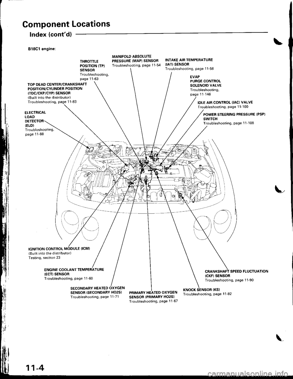
Index (cont'dl
B18C1 engine:
THROTTLEPOSITION (TP}
SENSORTroubleshooting,page 1 'l -63
MANIFOLD AESOLUTEPRESSURE IMAP) SENSORTroubleshooting, page 11_54
INTAKE AIR TEMPERATURE{IATI SENSORTroubleshooting, page 11'58
TOP DEAD CENTER/CRANKSHAFTPOSITION/CYLINOER POSITION
{TDC/CKP/CYP) SENSOR{BUilt into the distributor)Troubleshooting, page 1 1-83
EVAPPURGE CONTROLSOLENOID VALVETroubleshooting,page rr rqo
IDLE AIR CONTROL (IAC) VALVETroubleshooting, page 1 l-100
ELECTRICALLOAD
Troubleshooting,page 11 88
POWER STEERING PRESSURE IPSP}swtTcHTroubleshooting, page 'l1 108
IGNITION CONTROL
;- \
SENSOR {SECONDARY HO2S)
Troubleshooting, Page 1 1_71
(Built into the distributodTesting, section 23
ENGINE COOLANTIECD SENSORTroubleshooting, page 11 60
SECONDARY HEATED
SPEED FLUCTUATION(CKF) SENSORTroubleshooting, page 1 1-90
PRIMARY HEATED OXYGENKNOCK SENSOR IKSITroubleshooling, page 1 1_82SENSOR IPRIMARY HO2S)Troubleshooting, Page 11 67
il\
e)
11-4
Page 209 of 1680
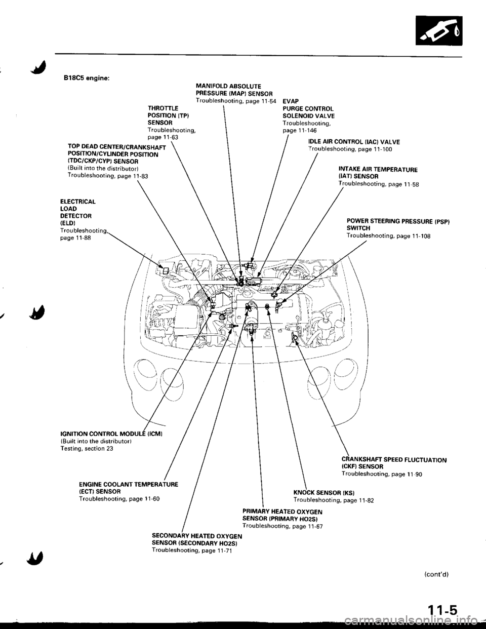
818C5 engine:MANIFOLD ABSOLUTEPRESSURE {MAPI SENSOFTroubleshooting, page 11 54 EVAPTHROTTLEPOSITION ITP}SENSORTroubleshooting,page 11 63
PURGE CONTROLSOLENOID VALVETroubleshooting,page 11 146
TOP DEAD CENTER/CRANKSHAFTPOSITION/CYLINDER POSITTONfiDC/CKP/CYP) SENSOR{Built into the distributor)Troubleshooting, page I t-83
IDLE AIR CONTROL IIAC) VALVETroubleshooting, page 11 100
INTAKE AIR TEMPERATUREIIAT) SENSOR
ELECTRICALLOADDETECTOR(ELD)
Troubleshootipage 11 88
Troubleshooting, page 1 1,58
POWER STEERING PRESSURE {PSP}swrTcHTroubleshooting, page 11 108
SPEEO FLUCTUATION{CKF} SENSORTroubleshooting, page 11 90
SENSOR (KS)Troubleshooting, page 1 1-82
ENGINE COOLANT TEMPENATUR€IECTI SENSORTroubleshootang, page 11-60
PRIMARY HEATED OXYGENSENSOR IPRIMARY HO2SITroubleshooting, page I1-67
HEATED OXYGENSENSOR ISECONDARY HO25)Troubleshootang, page 1 1,71
lcont'd)
1 1-5
,'(l)
Page 218 of 1680
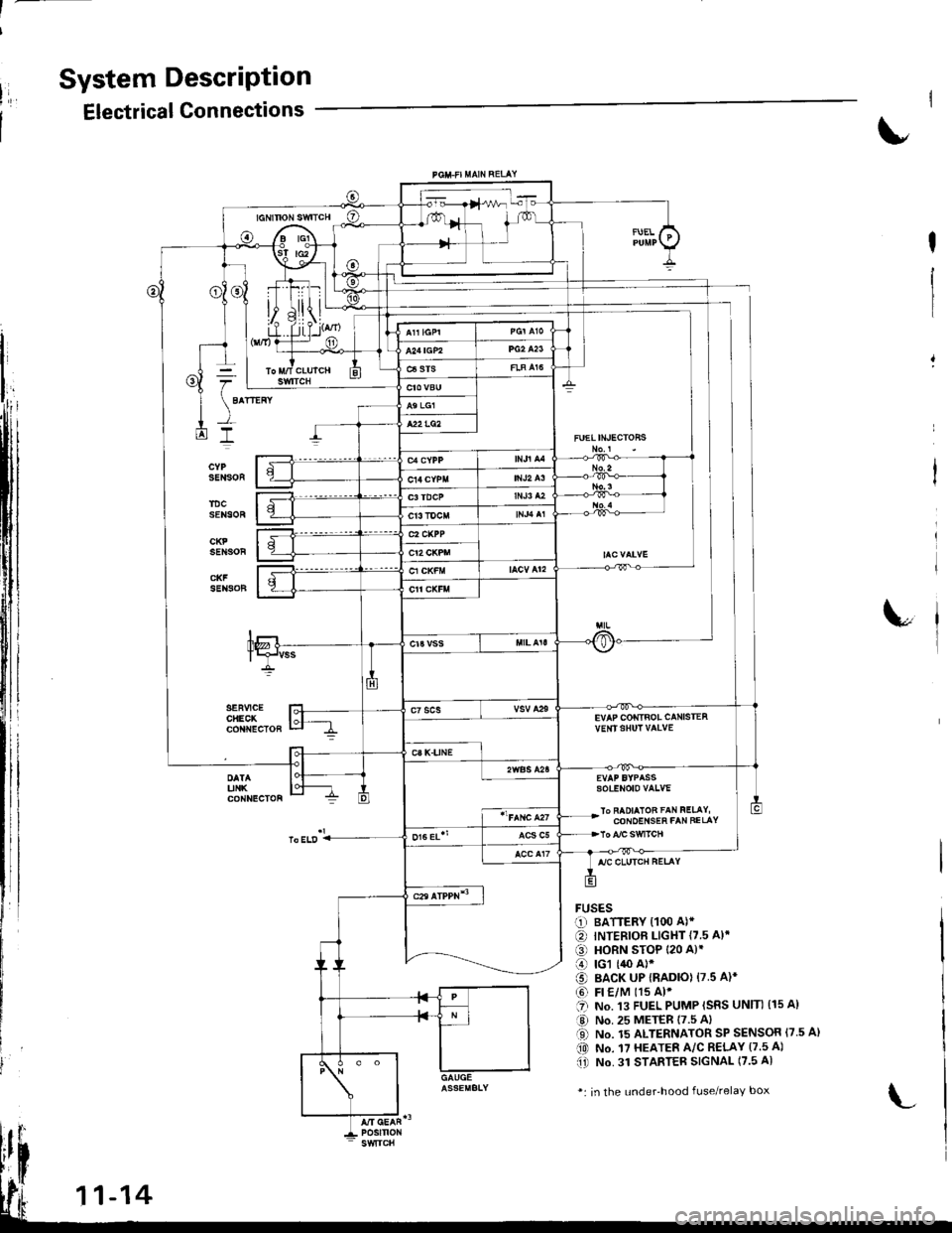
System DescriPtion
Electrical Connections
FUELIN'ECTOHS
EVAP COIiTIBOL CANISTEAvE|rISHUT VAIVE
sotENoto vaLvE
lo FAOIAIOB FAN FELAY,CONOEI{SEh FAN FELAY
FUSESr-1) BATTERY {100 A)*
€) INTERIOF LIGHT {7.5 A}.
€) HORN STOP 120 A)'
o rcl (,$ A)*
o BACK UP IRADIO) 17.5 A)*
@ Fr €/M t15 Al'.'I NO. .I3 FUEL PUMP ISRS UNIN (15 A)
a,J No. 25 METER 17.5 Al
O No. 15 ALTERNATOR SP SENSOR {7.5 A}(0 No. 17 HEATER A/C R€LAY (7.5 A)(i) No. 31 STAnTEB SIGNAL (7.5 A)
*: in the under'hood fuse/relaY box
Page 220 of 1680
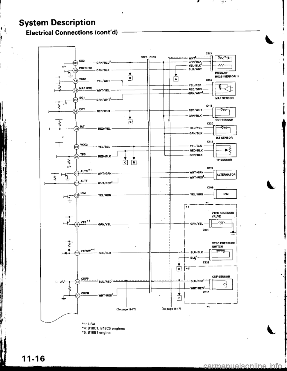
t;
System Description
sG2
Electrical Connections (cont'd)
c223 CiOSi
I
PO2SHTC
vccl
vcc2
cnl6lu'
OFN/BLK
YEVWHT
WHT/YEL
REO/YEL
YEVBLU
RED/ALX
WHI/qFN
TPS
neo,wrtrJffil
oFN/Btx--1-:JECt SE SOR
neonerJf$l
cnvELx--L# |IAT SENSOR
vsveLu--JJr[5lneozgr.x--_l F--? |cnN/Blx 1-:JfP SENSOR
".,.""11--,"u-l
I WECSOLENOIDI VALVE
VTEC PIIESSUFEswtTcH
-+ BLU/BLK - |----o o--l I- +- aq'- --l # |
+ i crdl
fr i-'-
t'=- - -
l
*-,*{Fli
,.,__!i
CXFSEN90B
._.._.._..J
PAI||ARYHO2S (SENSOR 1)cfl4ft'-------------1YEVBED ---l f .g--t- IFEo/cBN ___l F=-< f Icnr,wxr"_ lFj IIIAP SENSOB
cill
*4: 818C1, 818C5 engines*5: 81881 engine
11-16
Page 222 of 1680
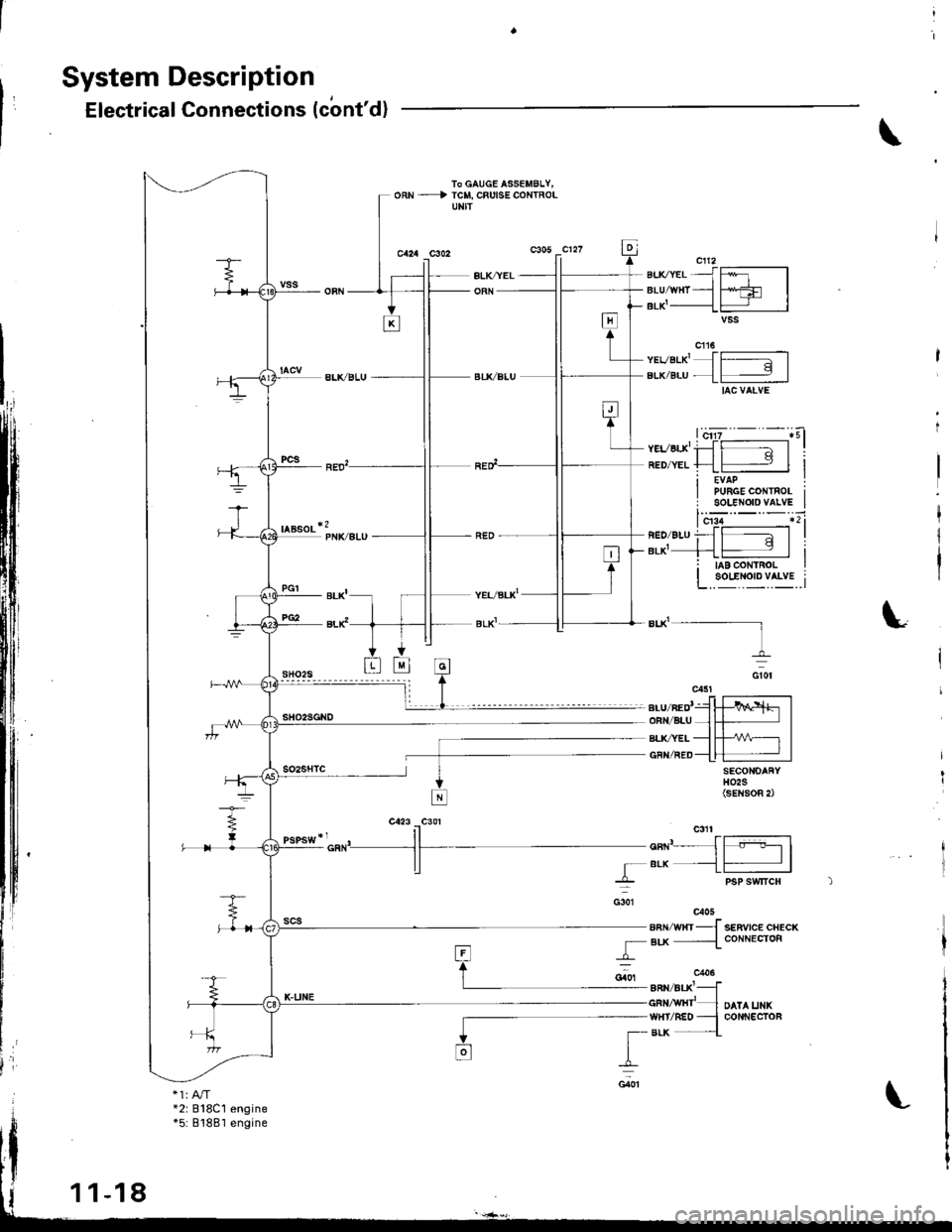
System Description
Electrical Connections (cbnt'd)
TO GAUGE ASSEMBLY,oRN - -) rclt, cFutsE coNTRoL
SECONOAFYH02S(sEtisoR 2)
f- -tl
T--lPgP SWTICH
u"n'--J
rBLK --L
G301
r
I_G40'l
eu.ter-{ffr-lBLU^'VHT - tsfi:l IBrK'____{l - |
vevar-x'Jffil
BLK/BLU.1- I
DATA UNKCOI{NECTOF
anvwrrJ senvrce crecx
{ Blx -{coNNEcroF
8nN,/BtxlJGFN/wHr'-WHI/REO -BLK . -.{
*2r 818C1engine*5: 81881 engine
1-18
L
Page 224 of 1680

System DescriPtion
,'Electrical Connections (cont'dl
\
c217WNT/RED -
YEVWTTT -
wrfi/BLU'-
c2t6wHt/BtJ( -
- BIJ(AEL -
- CRN/RED -
- Btx -
_L c21r
/Btx
UNDEFHOOD FUSE/RELAY 8OX
w{T
UNOEEDASH FUSE/RELAY BOX
'.'u^'o-Jfffi---]
| | A/r GEAR POSITION IELK/,!YHI--1| srvrrc1| (^'n Il{lf ic41a/T: c4t3
PTTP (SRS (lID O5A)
c/xltwrrzneo {IIEuc.YEL -l
BLVRED -I
ca:|9ar-uzwrrJwHr/?ED -l
IYEVGRN -t
c55lYEVBLU -f
c4a0ELX,/YEL {
*1: USA
11-20
Page 239 of 1680
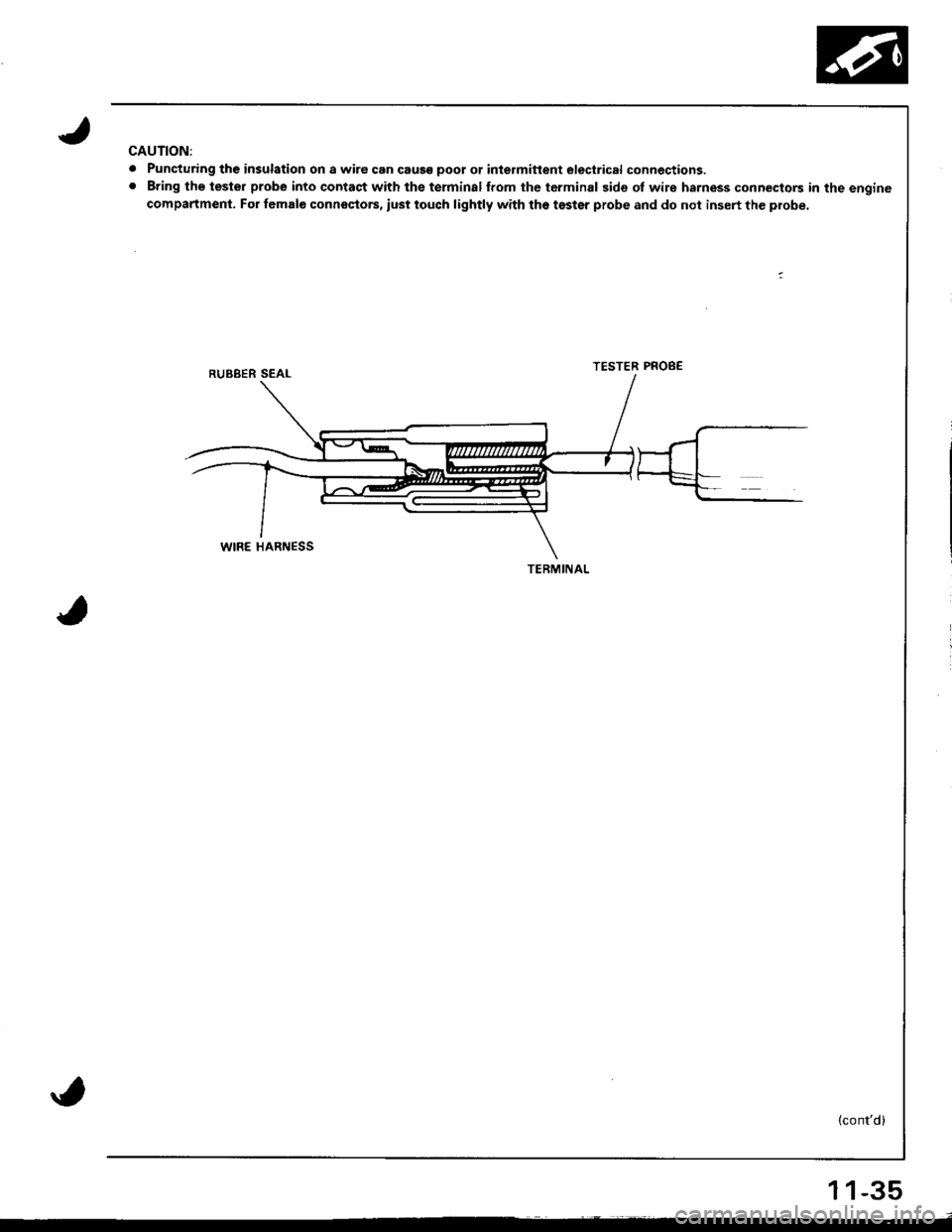
CAUTION:
. Puncturing th€ insulation on a wire can caus€ poot ot inlermitlent electrical connections.. Bring tho tester probe into contact with the terminalffom the tcrminal side of wire harness connectors in the engine
compartment. For female connestors, iust touch lightly with the tsster probe and do not insert the probe.
TESTER PROB€
(cont'd)
TERMINAL
11-35
Page 243 of 1680
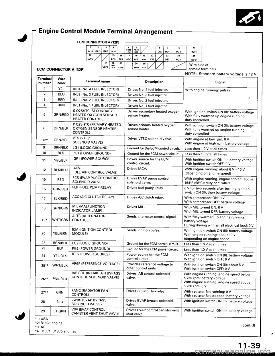
Engine Control Module Terminal Arrangement
ECM CONNECTOR A I32P}
ECM CONNECTOR A I32PI
*1: USA*2:818C1 engine*3:A,/T*4: 818C1, 818C5 engines
female terminals
NOTEr Standard battery voltageis 12 V.
{cont'di
LG22A
TerminalWireTerminal nameDescriptionSignal
YELlNJ4 (No. 4 FUEL INJECTOR)Drives No. 4 fuel iniector.With engine running: pulses2BLUlNJ3 (No.3 FUEL INJECTOR)Drives No. 3 fuel injector.
3REDlNJ2 (No.2 FUEL INJECTOB)Drives No.2 fuel injector.
BRNlNJl (No. 1 FUEL INJECTOR)Drives No. l Iuel iniector.
5GRN/REDS 02SHTC (SECONDARY
HEATED OXYGEN SENSORHEATER CONTROL)
Drives secondary heated oxygensensor heater,With ignition switch ON (ll)i battery volrageWith fully warmed up engine runningiduty controlled
6ORN/BLKP O2SHTC {PRIMARY HEAIEDOXYGEN SENSOB HEAIERCONTFOL)
Draves primary heated oxygensensor heater,With ignition swirch ON (ll): battery voltageWith lully warmed up engine running:duty controlled
84G RNI/ELVTS (VTEC
SOLENOID VALVE)Drives VTEC solenoid valve.With engine at low rpm: 0 VWith engine at high rpm: battery voltageIBRN/BLKLG1 (LOGIC GROUND)Ground for the ECM control circuit.Less than 1.0 V at alltimes10BLKPGl (POWER GROUND)Ground for the EC[, power circuit.Less than 1.0 V at all times't'lYEUBLKIGPl {POWER SOURCE)Power source for the ECMcontrolcircuit.With ignition switch ON 1ll): battery voltageWith ignition switch OFF| 0 V
12BLI(8LUIACV(IDLE AIR CONTROL VALVE}Drives IACV.With engine running: about 6 V 10 V(depending on engine speed)
REDPCS (EVAP PURGE CONTROLSOLENOID VALVE)Drives EVAP purge controlsolenoid valve.Wilh engane running, engine coolant above154"F (68'C): duty controlled
GRN/BLUFLR (FUEL PUMP RELAY)Drives fuel pump relay.0 V for two seconds after turning ignitionswitch ON (ll), then battery voltage
17B LVBEDACC (fuC CLUTCH RELAY)Drives A,/C clulch relay.With compressor ON: 0 VWith compressor OFFt baftery voltage
18GRN/ORNMIL (I\4ALFUNCTION
INDICATOR LAMPiDrives MlL.With MIL turned ON:0 VWjth MIL turned OFF: battery vottage
19*,WHT/GRNALTC (ALTERNATOR
CONTROL)Sends alternator control signal,With fully warmed up engine runninglbattery voltageDuring driving with small electrical load: 0 V
20YEUGRNICM (IGNITION CONTROLMODULE)Sends ignition pulse.With ignition switch ON (ll): battery voltageWith engine running: about'10 V(depending on engine speed)22BRN/BLKLG2 (LOGIC GROUND)Ground forthe ECM controlcifcuit.Less than 1.0 V at all times8LKPG2 (POWEfl GROUND)Ground for the ECM power circuit.Less than 1.0 V at all times
24YEUELKIGP2 (POWER SOURCE)Power source for the ECMcontrolcircuit,With ignition switch ON {lli: battery voltageWith ignition switch OFF: 0 V
25*3WHT/BLKVREF (REFERENCE VOLTAGE)Provides reference voltage toother control units,With ignition swirch ON (ll): about 5 VWath ignition switch OFF: 0 V
26. 'PNK/8LU
IAB SOL (INTAKE AIR BYPASSCONTROL SOLENOID VALVE)Drives IAB conlrol solenoidWith engrne running, engrae speed betow5,750 rpm: battery voltageWith engine running, engine speed above5,750 rpm: 0 V
27* IGRNFANC (BADIATOR FANCONTROL)Drives radiator fan relay.With radiator {an running: 0 VWith radiator Ian stopped: battery voltage
2ABLU2WBS (EVAP BYPASSSOLENOID VALVE)Drives EVAP bypass solenoidWith ignition switch ON (ll): battery vottage
29LT GRNVSV (EVAP CONlROLCANISTER VENT SHUT VAVLE)Drives EVAP control canister ventshut valve.Wilh ignilion switch ON lll): banery votrasc
1 1-39