ad blue ACURA NSX 1991 Service Repair Manual
[x] Cancel search | Manufacturer: ACURA, Model Year: 1991, Model line: NSX, Model: ACURA NSX 1991Pages: 1640, PDF Size: 60.48 MB
Page 89 of 1640

Timing Belt
Inspection
1. Remove the ignition coil covers and harness clamps.
2. Disconnect the connectors, then remove the ignition
coils.
3. Remove the cylinder head covers,
4. Inspect the timing belt for cracks and coolant or oil soaking.
NOTE:
Replace the belt if coolant or oil soaked.
Remove any oil or solvent that gets on the belt.
Inspect this area
for wear.
Rotate pulley and
Inspect belt.
Tension Adjustment
CAUTION:
Always adjust timing belt tension with the engine cold
Do not rotate the crankshaft when the adjusting bolt
is loose (the timing belt will skid over the teeth of
the rear intake caimshaft pulley).
Adjust the belt tension only when the belt has been
removed and reinstalled or replaced.
NOTE:
Tensioner is spring-loaded to apply proper tension to
the belt automatically after making the following ad-
justment. Inspect the timing belt before adjusting the belt
tension.
Always rotate the crankshaft clockwise. Rotating it
counterclockwise may result in improper adjustment
of the belt tension or cause the belt to jump a tooth
on the camshaft pulleys.
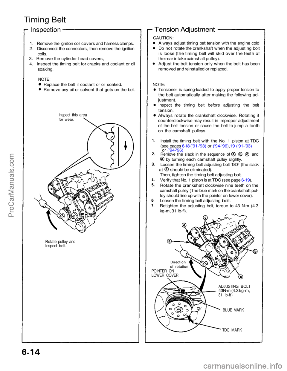
Install the timing beIt with the No. 1 piston at TDC
(see pages 6-18 ('91-'93) or ('94-'96),19 ('91-'93)
or ('94-'96) Remove the slack in the sequence of , and
by turning each camshaft pulley slightly.
Loosen the timing belt adjusting bolt 180° (the slack
at should be eliminated).
Then, tighten the timing belt adjusting bolt.
Verify that No. 1 piston is at TDC (see page 6-19).
Rotate the crankshaft clockwise nine teeth on the
camshaft pulley (The blue mark on the crankshaft pul- ley should line up with the pointer on lower cover).
Loosen
the
timing
belt
adjusting
bolt.
Retighten the adjusting bolt, torque to 43 N·m (4.3
kg-m, 31 Ib-fl).
Direction
of rotation
POINTER ON
LOWER COVER
ADJUSTING BOLT
43N·m (4.3 kg-m,
31 Ib-ft)
BLUE MARK
TDC MARK
ProCarManuals.com
Page 363 of 1640

Differential
Reassembly
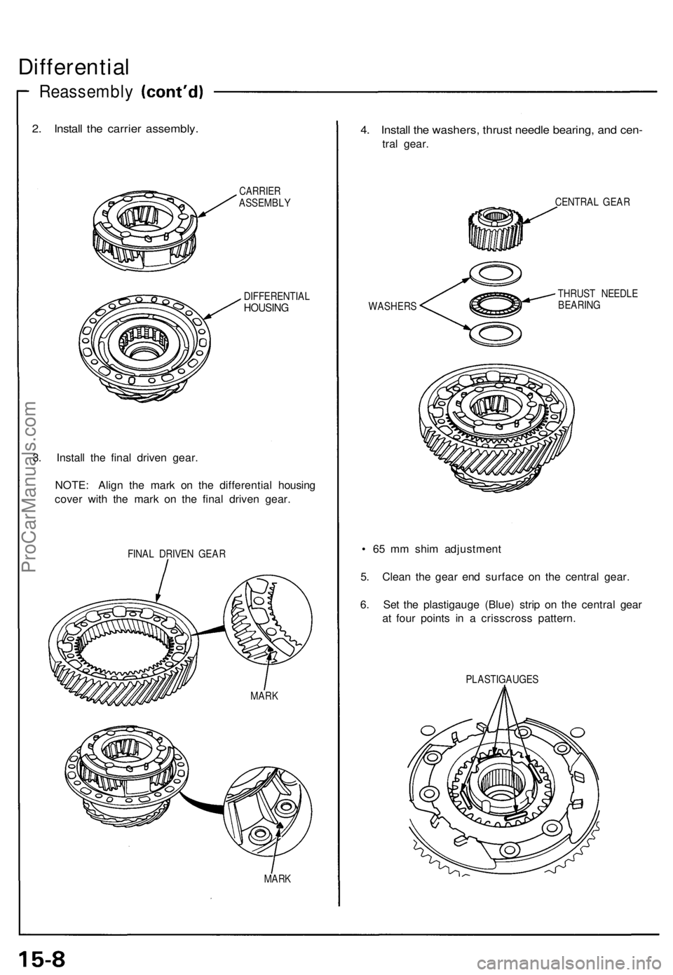
2. Install the carrier assembly.
CARRIER
ASSEMBLY
DIFFERENTIAL
HOUSING
3. Install the final driven gear.
NOTE: Align the mark on the differential housing
cover with the mark on the final driven gear.
FINAL DRIVEN GEAR
MARK
4. Install the washers, thrust needle bearing, and cen-
tral gear.
CENTRAL GEAR
WASHERS
THRUST NEEDLE
BEARING
• 65 mm shim adjustment
5. Clean the gear end surface on the central gear.
6. Set the plastigauge (Blue) strip on the central gear
at four points in a crisscross pattern.
PLASTIGAUGES
MARKProCarManuals.com
Page 1008 of 1640

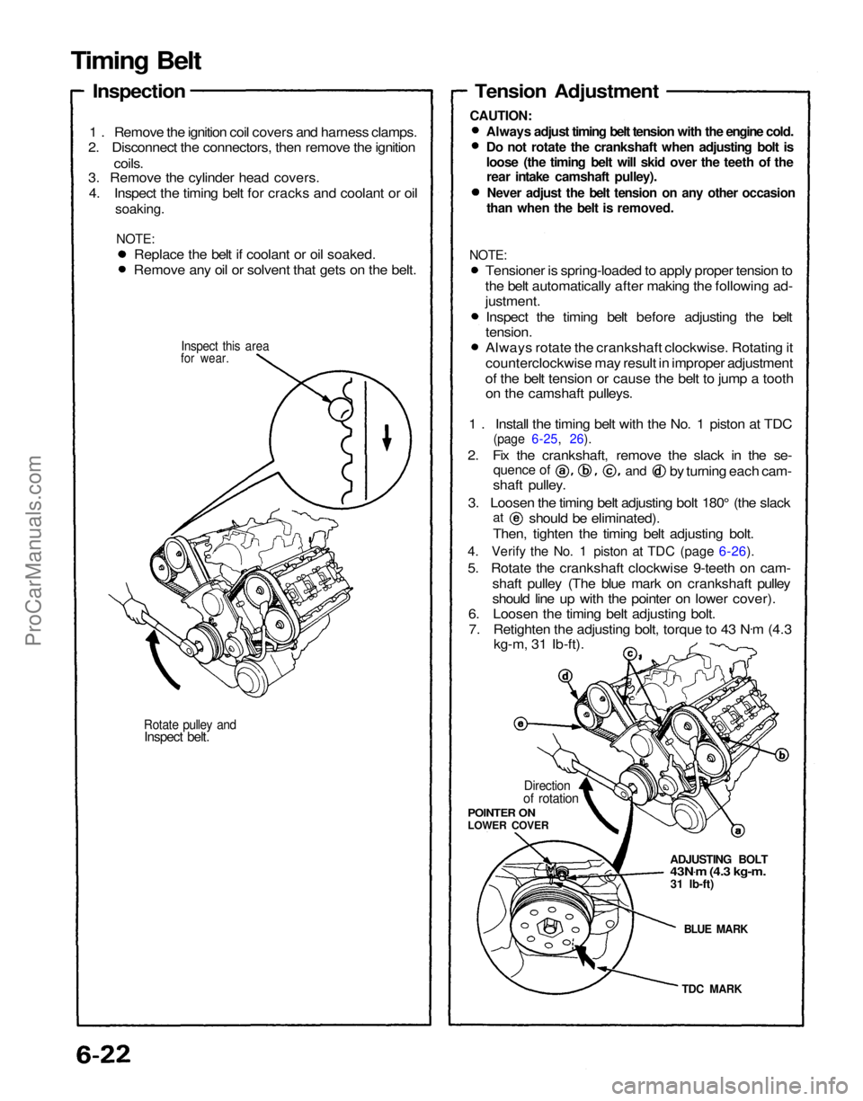
Rotate pulley and
Inspect belt.
for wear.
1 . Remove the ignition coil covers and harness clamps.
2. Disconnect the connectors, then remove the ignition
coils.
3. Remove the cylinder head covers.
4. Inspect the timing belt for cracks and coolant or oil
soaking.
NOTE:
TDC MARK
BLUE MARK
ADJUSTING BOLT
43N
.
m (4.3 kg-m.
31 Ib-ft)
Direction
of rotation
POINTER ON
LOWER COVER
Tension Adjustment
Always adjust timing belt tension with the engine cold.
Do not rotate the crankshaft when adjusting bolt is
loose (the timing belt will skid over the teeth of the
rear intake camshaft pulley).
Never adjust the belt tension on any other occasion
than when the belt is removed.
shaft pulley.
3. Loosen the timing belt adjusting bolt 180° (the slack
Then, tighten the timing belt adjusting bolt.
4. Verify the No. 1 piston at TDC (page 6-26).
5. Rotate the crankshaft clockwise 9-teeth on cam- shaft pulley (The blue mark on crankshaft pulley
should line up with the pointer on lower cover).
6. Loosen the timing belt adjusting bolt.
7. Retighten the adjusting bolt, torque to 43 N .
m (4.3
kg-m, 31 Ib-ft).
at
should be eliminated).
quence of
and
by turning each cam-
Replace the belt if coolant or oil soaked.
Remove any oil or solvent that gets on the belt.
Inspect this area
Timing Belt
Inspection
CAUTION:
NOTE:
Tensioner is spring-loaded to apply proper tension to
the belt automatically after making the following ad-
justment.
Inspect the timing belt before adjusting the belt
tension.
Always rotate the crankshaft clockwise. Rotating it
counterclockwise may result in improper adjustment
of the belt tension or cause the belt to jump a tooth on the camshaft pulleys.
1 . Install the timing belt with the No. 1 piston at TDC
(page 6-25, 26).
2. Fix the crankshaft, remove the slack in the se-ProCarManuals.com
Page 1029 of 1640

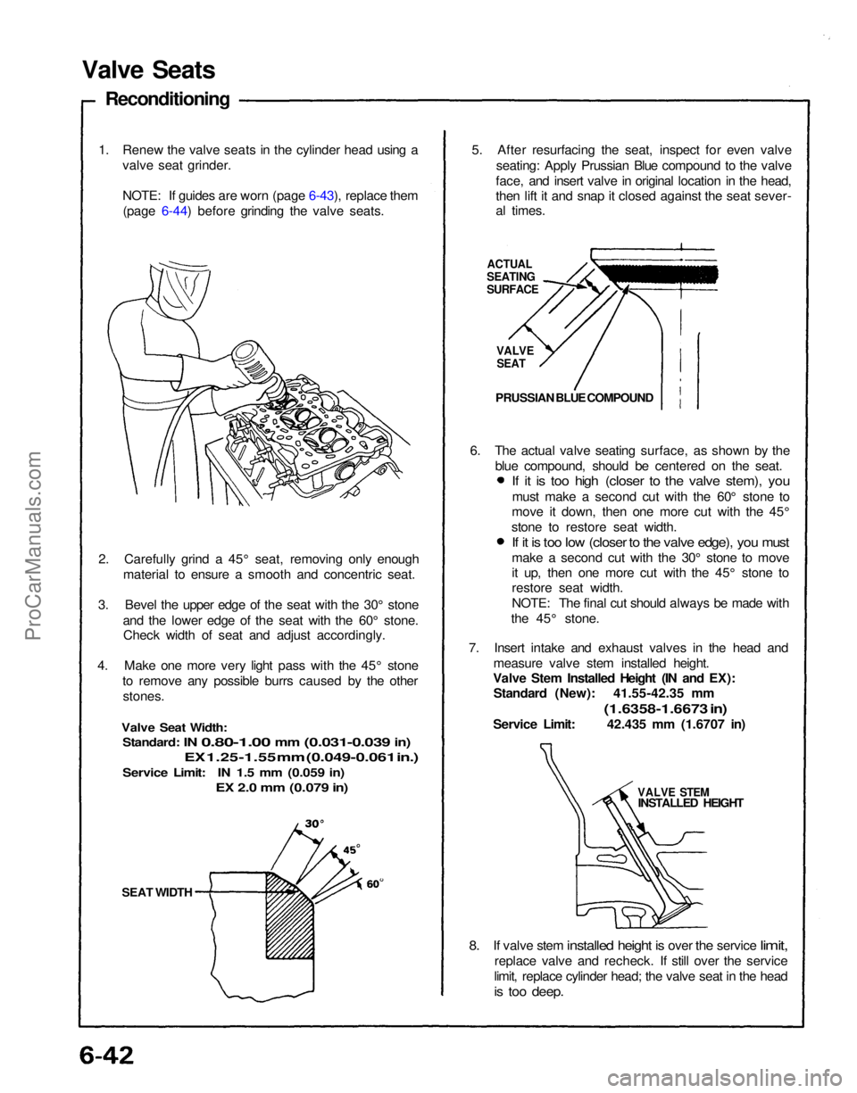
SEAT WIDTH
2. Carefully grind a 45° seat, removing only enough
material to ensure a smooth and concentric seat.
3. Bevel the upper edge of the seat with the 30° stone and the lower edge of the seat with the 60° stone.Check width of seat and adjust accordingly.
4. Make one more very light pass with the 45° stone to remove any possible burrs caused by the otherstones.
Valve Seat Width:
Standard:
IN
0.80-1.00
mm
(0.031-0.039
in)
EX 1.25-1.55 mm (0.049-0.061 in.)
Service Limit: IN 1.5 mm (0.059 in)
EX 2.0 mm (0.079 in)
1. Renew the valve seats in the cylinder head using a
valve seat grinder.
NOTE: If guides are worn (page 6-43), replace them(page 6-44) before grinding the valve seats.
Valve Seats
Reconditioning
5. After resurfacing the seat, inspect for even valveseating: Apply Prussian Blue compound to the valve
face, and insert valve in original location in the head,
then lift it and snap it closed against the seat sever-
al times.
ACTUAL
SEATING
SURFACE
VALVE
SEAT
PRUSSIAN BLUE COMPOUND
7. Insert intake and exhaust valves in the head and measure valve stem installed height.
Valve Stem Installed Height (IN and EX): Standard (New): 41.55-42.35 mm
(1.6358-1.6673 in)
Service Limit: 42.435 mm (1.6707 in)
VALVE STEM
INSTALLED HEIGHT
8. If
valve stem
installed
height
is
over
the
service
limit,
replace valve and recheck. If still over the service
limit, replace cylinder head; the valve seat in the head
is too deep.
6. The actual valve seating surface, as shown by the
blue compound, should be centered on the seat.
If it is too high (closer to the valve stem), you
must make a second cut with the 60° stone to
move it down, then one more cut with the 45°
stone to restore seat width.
If it is too low (closer to the valve edge), you must
make a second cut with the 30° stone to move
it up, then one more cut with the 45° stone to
restore seat width.
NOTE: The final cut should always be made with
the 45° stone.ProCarManuals.com