belt ACURA NSX 1991 Service Repair Manual
[x] Cancel search | Manufacturer: ACURA, Model Year: 1991, Model line: NSX, Model: ACURA NSX 1991Pages: 1640, PDF Size: 60.48 MB
Page 7 of 1640
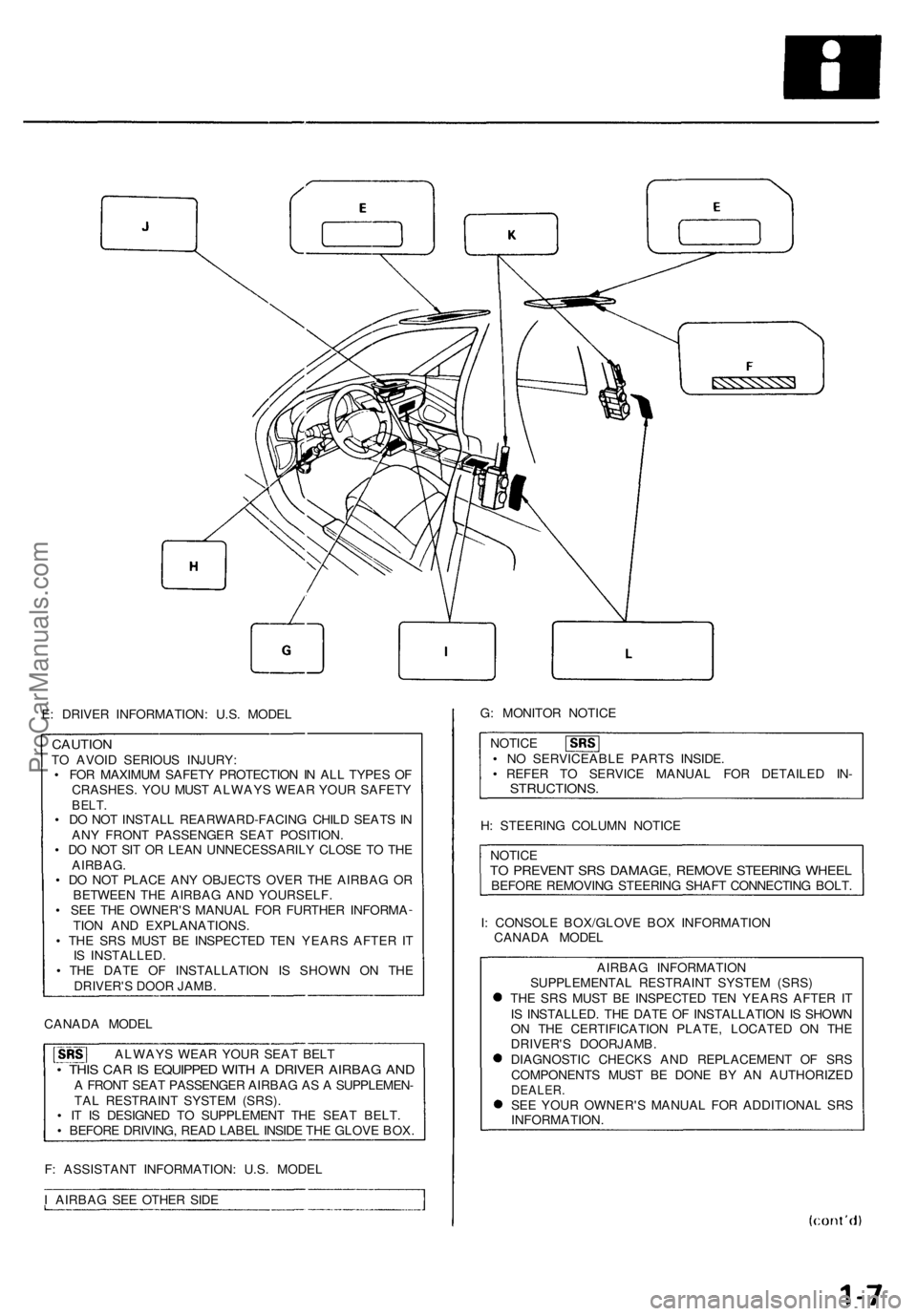
E: DRIVE R INFORMATION : U.S . MODE L
CAUTIO NTO AVOI D SERIOU S INJURY :
• FO R MAXIMU M SAFET Y PROTECTIO N IN AL L TYPE S O F
CRASHES . YO U MUS T ALWAY S WEA R YOU R SAFET Y
BELT.• D O NO T INSTAL L REARWARD-FACIN G CHIL D SEAT S IN
AN Y FRON T PASSENGE R SEA T POSITION .
• D O NO T SI T O R LEA N UNNECESSARIL Y CLOS E T O TH E
AIRBAG .
• D O NO T PLAC E AN Y OBJECT S OVE R TH E AIRBA G O R
BETWEE N TH E AIRBA G AN D YOURSELF .
• SE E TH E OWNER' S MANUA L FO R FURTHE R INFORM A
TIO N AN D EXPLANATIONS .
• TH E SR S MUS T B E INSPECTE D TE N YEAR S AFTE R IT
I S INSTALLED .
• TH E DAT E O F INSTALLATIO N I S SHOW N O N TH E
DRIVER'S DOOR JAMB.
CANAD A MODE L
ALWAY S WEA R YOU R SEA T BEL T
• THI S CA R IS EQUIPPE D WIT H A DRIVE R AIRBA G AN DA FRON T SEA T PASSENGE R AIRBA G A S A SUPPLEMEN -
TA L RESTRAIN T SYSTE M (SRS) .
• I T I S DESIGNE D T O SUPPLEMEN T TH E SEA T BELT .
• BEFOR E DRIVING , REA D LABE L INSID E TH E GLOV E BOX .
F : ASSISTAN T INFORMATION : U.S . MODE L
I AIRBA G SE E OTHE R SID E G
: MONITO R NOTIC E
NOTIC E
• N O SERVICEABL E PART S INSIDE .
• REFE R T O SERVIC E MANUA L FO R DETAILE D IN -
STRUCTIONS .
H: STEERIN G COLUM N NOTIC E
NOTIC E
TO PREVEN T SR S DAMAGE , REMOV E STEERIN G WHEE LBEFOR E REMOVIN G STEERIN G SHAF T CONNECTIN G BOLT .
I : CONSOL E BOX/GLOV E BO X INFORMATIO N
CANAD A MODE L
AIRBA G INFORMATIO N
SUPPLEMENTA L RESTRAIN T SYSTE M (SRS )
TH E SR S MUS T B E INSPECTE D TE N YEAR S AFTE R IT
I S INSTALLED . TH E DAT E O F INSTALLATIO N IS SHOW N
O N TH E CERTIFICATIO N PLATE , LOCATE D O N TH E
DRIVER' S DOORJAMB .
DIAGNOSTI C CHECK S AN D REPLACEMEN T O F SR S
COMPONENT S MUS T B E DON E B Y A N AUTHORIZE D
DEALER.SEE YOU R OWNER' S MANUA L FO R ADDITIONA L SR S
INFORMATION .
ProCarManuals.com
Page 8 of 1640
Warning/Caution Label Locations
J: PASSENGER'S INFLATOR CAUTION
DANGER
EXPLOSIVE/FLAMMABLE
CONTACT WITH ACID, WATER OR HEAVY METALS SUCH
AS COPPER, LEAD OR MERCURY MAY PRODUCE HARM-
FUL AND IRRITATING GASES OR EXPLOSIVE COM-
POUNDS.
STORAGE TEMPERATURES MUST NOT EXCEED 200°F
(100°C). FOR PROPER HANDLING, STORAGE AND DIS-
POSAL PROCEDURES REFER TO SERVICE MANUAL, SRS
SUPPLEMENT.
POISON
CONTAINS POISONOUS SODIUM AZIDE AND POTASSIUM
NITRATE.
FIRST AID
IF CONTENTS ARE SWALLOWED, INDUCE VOMITING.
FOR EYE CONTACT, FLUSH EYES WITH WATER FOR 15
MINUTES.
IF GASES (FROM ACID OR WATER CONTACT) ARE IN-
HALED. SEEK FRESH AIR. IN EVERY CASE, GET PROMPT
MEDICAL ATTENTION.
KEEP OUT OF REACH OF CHILDREN.
THE AIRBAG INFLATOR IS EXPLOSIVE AND, IF ACCIDEN-
TALLY DEPLOYED, CAN SERIOUSLY HURT OR KILL YOU.
• DO NOT USE ELECTRICAL TEST EQUIPMENT OR PROB-
ING DEVICES.
THEY CAN CAUSE ACCIDENTAL DEPLOYMENT.
• NO SERVICEABLE PARTS INSIDE. DO NOT DISAS-
SEMBLE.
• PLACE AIRBAG UPRIGHT WHEN REMOVED.
• FOLLOW SERVICE MANUAL INSTRUCTIONS
CAREFULLY.
K: TENSIONER POWER SOURCE CAUTION
SEAT BELT TENSIONER
DO NOT TAMPER. REFER TO SERVICE MANUAL FOR COM-
PLETE INSTRUCTIONS.
L: TENSIONER ELR CAUTION
WARNING
EXPLOSIVE MATERIAL INSIDE
YOU CAN BE SERIOUSLY HURT OR BURNED.
• INSTALL RED SHORT CONNECTOR WHEN WIRE HAR
NESS IS DISCONNECTED.
• DO NOT TAMPER OR DISASSEMBLE.
NO SERVICEABLE PARTS INSIDE.
• USE ONLY APPROVED ELECTRICAL TESTERS FOR CIR-
CUIT DIAGNOSIS.
REFER TO SERVICE MANUAL FOR COMPLETE IN-
STRUCTIONS.
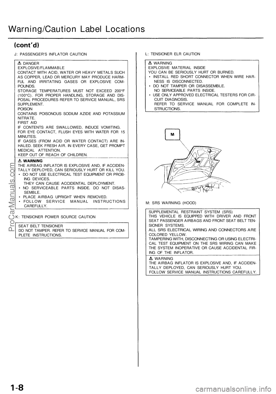
M: SRS WARNING (HOOD)
SUPPLEMENTAL RESTRAINT SYSTEM (SRS)
THIS VEHICLE IS EQUIPPED WITH DRIVER AND FRONT
SEAT PASSENGER AIRBAGS AND FRONT SEAT BELT TEN-
SIONER SYSTEMS.
ALL SRS ELECTRICAL WIRING AND CONNECTORS ARE
COLORED YELLOW.
TAMPERING WITH, DISCONNECTING OR USING ELECTRI-
CAL TEST EQUIPMENT ON THE SRS WIRING CAN MAKE
THE SYSTEM INOPERATIVE OR CAUSE ACCIDENTAL FIR-
ING OF THE INFLATOR.
WARNING
THE AIRBAG INFLATOR IS EXPLOSIVE AND, IF ACCIDEN-
TALLY DEPLOYED, CAN SERIOUSLY HURT YOU.
FOLLOW SERVICE MANUAL INSTRUCTIONS CAREFULLY.ProCarManuals.com
Page 22 of 1640
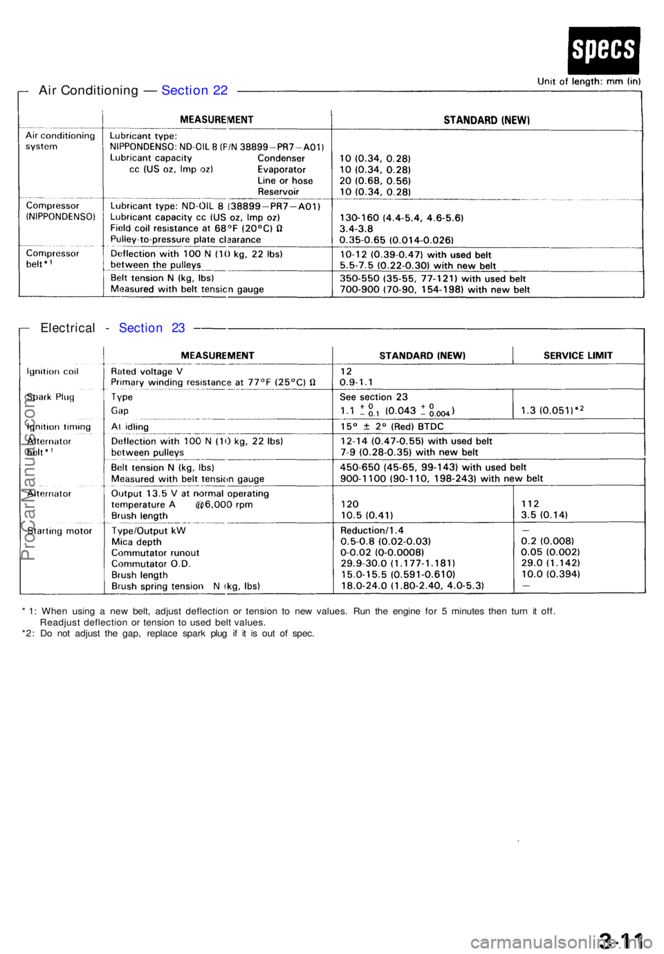
* 1 : Whe n usin g a ne w belt , adjus t deflectio n o r tensio n t o ne w values . Ru n th e engin e fo r 5 minute s the n tur n i t off .
Readjus t deflectio n o r tensio n t o use d bel t values .
*2 : D o no t adjus t th e gap , replac e spar k plu g i f i t i s ou t o f spec .
Electrica l - Sectio n 2 3
Air Conditionin g — Sectio n 2 2
ProCarManuals.com
Page 39 of 1640
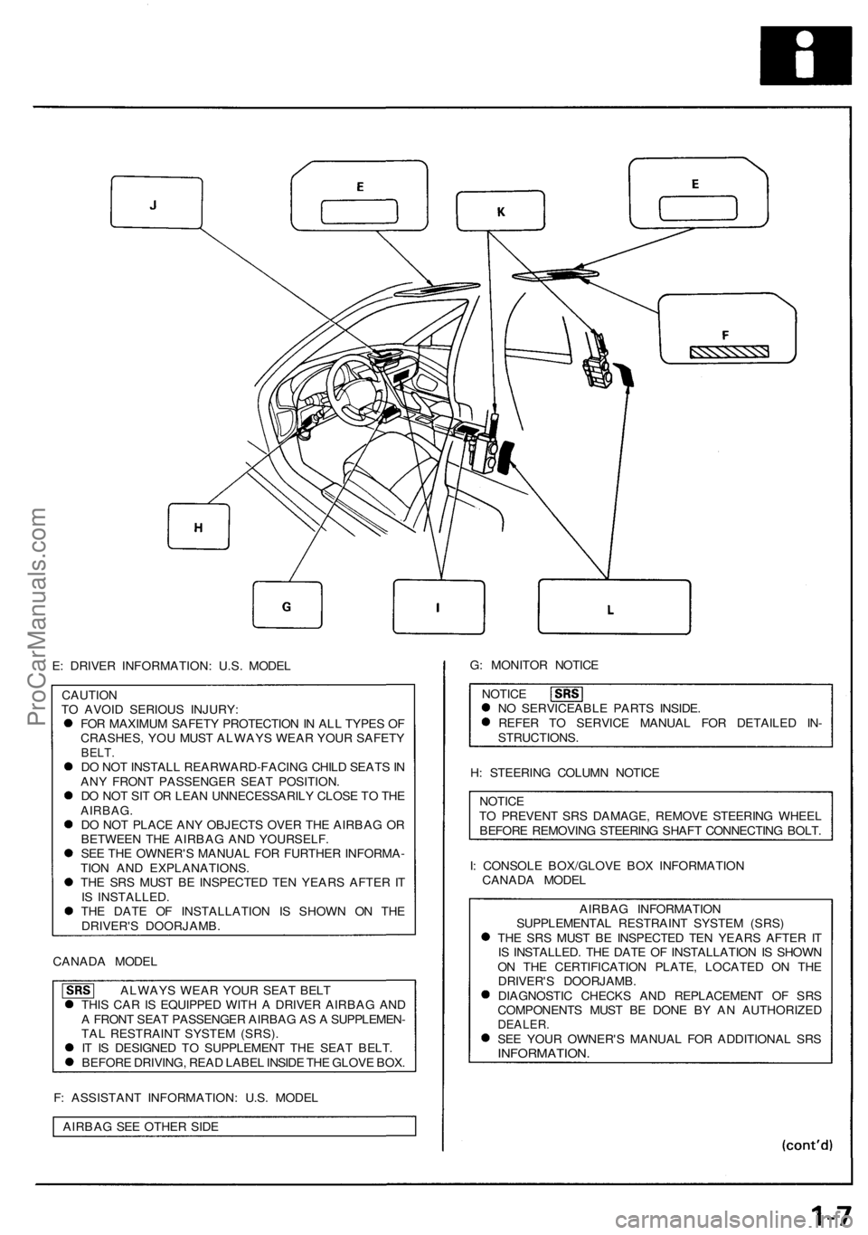
E: DRIVER INFORMATION: U.S. MODEL
CAUTION
TO AVOID SERIOUS INJURY:
FOR MAXIMUM SAFETY PROTECTION IN ALL TYPES OF
CRASHES, YOU MUST ALWAYS WEAR YOUR SAFETY
BELT.
DO NOT INSTALL REARWARD-FACING CHILD SEATS IN
ANY FRONT PASSENGER SEAT POSITION.
DO NOT SIT OR LEAN UNNECESSARILY CLOSE TO THE
AIRBAG.
DO NOT PLACE ANY OBJECTS OVER THE AIRBAG OR
BETWEEN THE AIRBAG AND YOURSELF.
SEE THE OWNER'S MANUAL FOR FURTHER INFORMA-
TION AND EXPLANATIONS.
THE SRS MUST BE INSPECTED TEN YEARS AFTER IT
IS INSTALLED.
THE DATE OF INSTALLATION IS SHOWN ON THE
DRIVER'S DOORJAMB.
CANADA MODEL
ALWAYS WEAR YOUR SEAT BELT
THIS CAR IS EQUIPPED WITH A DRIVER AIRBAG AND
A FRONT SEAT PASSENGER AIRBAG AS A SUPPLEMEN-
TAL RESTRAINT SYSTEM (SRS).
IT IS DESIGNED TO SUPPLEMENT THE SEAT BELT.
BEFORE DRIVING, READ LABEL INSIDE THE GLOVE BOX.
F: ASSISTANT INFORMATION: U.S. MODEL
AIRBAG SEE OTHER SIDE
G: MONITOR NOTICE
NOTICE
NO SERVICEABLE PARTS INSIDE.
REFER TO SERVICE MANUAL FOR DETAILED IN-
STRUCTIONS.
H: STEERING COLUMN NOTICE
NOTICE
TO PREVENT SRS DAMAGE, REMOVE STEERING WHEEL
BEFORE REMOVING STEERING SHAFT CONNECTING BOLT.
I: CONSOLE BOX/GLOVE BOX INFORMATION
CANADA MODEL
AIRBAG INFORMATION
SUPPLEMENTAL RESTRAINT SYSTEM (SRS)
THE SRS MUST BE INSPECTED TEN YEARS AFTER IT
IS INSTALLED. THE DATE OF INSTALLATION IS SHOWN
ON THE CERTIFICATION PLATE, LOCATED ON THE
DRIVER'S DOORJAMB.
DIAGNOSTIC CHECKS AND REPLACEMENT OF SRS
COMPONENTS MUST BE DONE BY AN AUTHORIZED
DEALER.
SEE YOUR OWNER'S MANUAL FOR ADDITIONAL SRS
INFORMATION.ProCarManuals.com
Page 58 of 1640
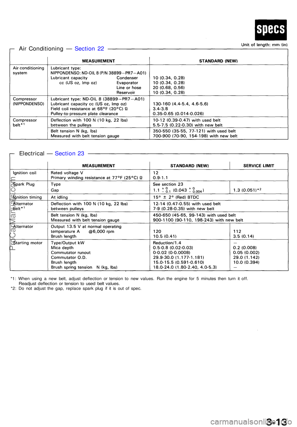
Air Conditionin g — Sectio n 2 2
Electrica l — Sectio n 2 3
*1 : Whe n usin g a ne w belt , adjus t deflectio n o r tensio n t o ne w values . Ru n th e engin e fo r 5 minute s the n tur n i t off .Readjus t deflectio n o r tensio n t o use d bel t values .*2: D o no t adjus t th e gap , replac e spar k plu g i f i t i s ou t o f spec .
ProCarManuals.com
Page 74 of 1640
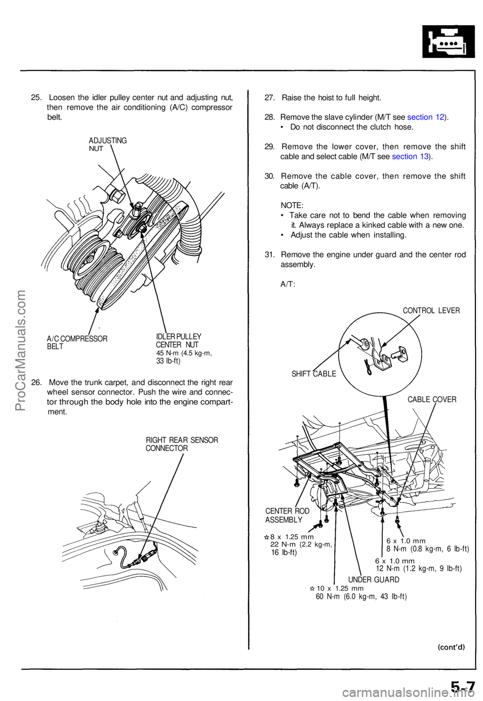
25. Loose n th e idle r pulle y cente r nu t an d adjustin g nut ,
the n remov e th e ai r conditionin g (A/C ) compresso r
belt.
ADJUSTIN GNUT
A/C COMPRESSO RBELT
IDLE R PULLE Y
CENTE R NU T
45 N- m (4. 5 kg-m ,33 Ib-ft )
26. Mov e th e trun k carpet , an d disconnec t th e righ t rea r
whee l senso r connector . Pus h th e wir e an d connec -
tor throug h th e bod y hol e int o th e engin e compart -
ment.
RIGH T REA R SENSO R
CONNECTO R
27. Rais e th e hois t t o ful l height .
28 . Remov e th e slav e cylinde r (M/ T se e sectio n 12 ).
• D o no t disconnec t th e clutc h hose .
29 . Remov e th e lowe r cover , the n remov e th e shif t
cabl e an d selec t cabl e (M/ T se e sectio n 13 ).
30 . Remov e th e cabl e cover , the n remov e th e shif t
cabl e (A/T) .
NOTE :
• Tak e car e no t t o ben d th e cabl e whe n removin g
it . Alway s replac e a kinke d cabl e wit h a ne w one .
• Adjus t th e cabl e whe n installing .
31 . Remov e th e engin e unde r guar d an d th e cente r ro d
assembly .
A/T:
CONTRO L LEVE R
CENTE R RO D
ASSEMBL Y
8 x 1.2 5 mm22 N- m (2. 2 kg-m ,16 Ib-ft )
6 x 1. 0 m m8 N- m (0. 8 kg-m , 6 Ib-ft )
6 x 1. 0 m m12 N- m (1. 2 kg-m , 9 Ib-ft )
UNDE R GUAR D
10 x 1.2 5 mm60 N- m (6. 0 kg-m , 4 3 Ib-ft )
SHIF
T CABL E
CABLE COVE R
ProCarManuals.com
Page 80 of 1640
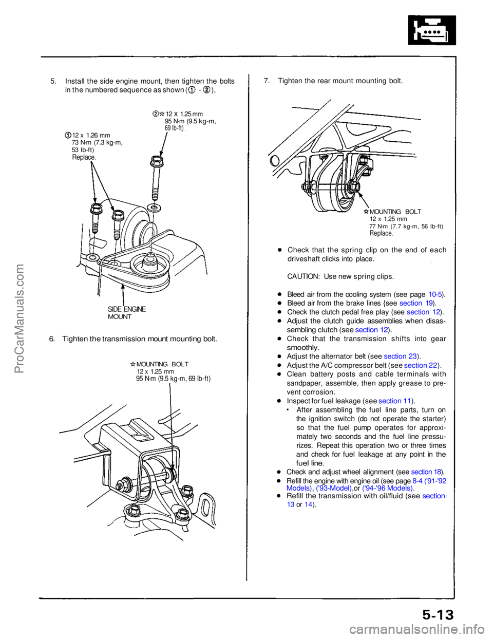
5. Install the side engine mount, then tighten the bolts
in the numbered sequence as shown ( - ),
12 x
1.26
mm
73 N·m
(7.3 kg-m,
53 Ib-ft)
Replace.
12 x
1.25
mm
95 N·m
(9.5 kg-m,
69 Ib-ft)
SIDE ENGINE
MOUNT
6. Tighten the transmission mount mounting bolt.
MOUNTING BOLT
12 x
1.25
mm
95 N·m (9.5 kg-m, 69 Ib-ft)
7. Tighten the rear mount mounting bolt.
MOUNTING BOLT
12 x
1.25
mm
77 N·m (7.7 kg-m, 56 Ib-ft)
Replace.
Check that the spring clip on the end of each
driveshaft clicks into place.
CAUTION: Use new spring clips.
Bleed air from the cooling system (see page 10-5).
Bleed air from the brake lines {see section 19).
Check the clutch pedal free play (see section 12).
Adjust the clutch guide assemblies when disas-
sembling clutch (see section 12).
Check that the transmission shifts into gear
smoothly.
Adjust the alternator belt (see section 23).
Adjust the A/C compressor belt (see section 22).
Clean battery posts and cable terminals with
sandpaper, assemble, then apply grease to pre-
vent corrosion.
Inspect for fuel leakage (see section 11). After assembling the fuel line parts, turn on
the ignition switch (do not operate the starter) so that the fuel pump operates for approxi-
mately two seconds and the fuel line pressu-
rizes. Repeat this operation two or three times
and check for fuel leakage at any point in the
fuel line.
Check and adjust wheel alignment (see section 18).
Refill the engine with engine oil (see page 8-4 ('91-'92
Models), ('93-Model),or ('94-'96 Models).
Refill the transmission with oil/fluid (see section
13 or
14).ProCarManuals.com
Page 83 of 1640
Rocker Arms
Manual Inspection
1. Remove the ignition coil covers (see page 6-15 ('91-'93) or ('94-'96)
2. Remove the ignition coils (see page 6-15 ('91-'93)or ('94-'96).
3. Remove the cylinder head covers.
NOTE: Refer to pages 6-47 ('91-'93)
or ('94-'96) ,48 ('91-'93)
or ('94-'96) when installing the cylinder head cover.
4. Set the No. 1 piston at top dead center (TDC) (see
page 6-19 ('91-'93)
or ('94-'96).
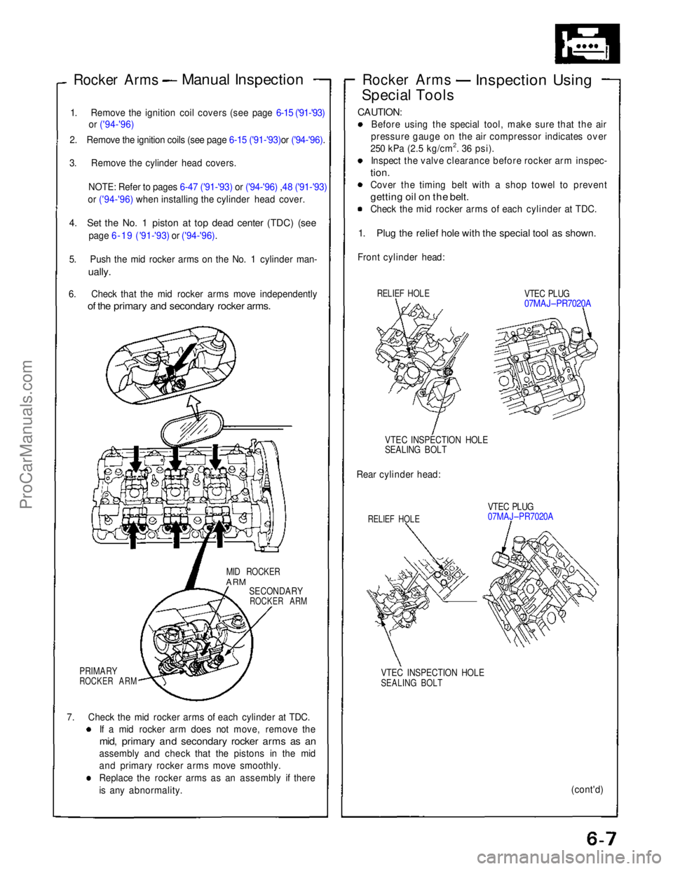
5. Push the mid rocker arms on the No. 1 cylinder man-
ually.
6. Check that the mid rocker arms move independently
of the primary and secondary rocker arms.
MID ROCKER
ARM
SECONDARY
ROCKER ARM
PRIMARY
ROCKER ARM
7. Check the mid rocker arms of each cylinder at TDC. If a mid rocker arm does not move, remove the
mid, primary and secondary rocker arms as an
assembly and check that the pistons in the mid
and primary rocker arms move smoothly.
Replace the rocker arms as an assembly if there
is any abnormality. Rocker Arms
Inspection Using
Special Tools
CAUTION:
Before using the special tool, make sure that the air
pressure gauge on the air compressor indicates over
250 kPa (2.5 kg/cm2. 36 psi). Inspect the valve clearance before rocker arm inspec-
tion.
Cover the timing belt with a shop towel to prevent
getting oil on the belt.
Check the mid rocker arms of each cylinder at TDC.
1. Plug the relief hole with the special tool as shown.
Front cylinder head:
RELIEF HOLE
VTEC PLUG
07MAJ–PR7020A
VTEC INSPECTION HOLE
SEALING BOLT
Rear cylinder head:
RELIEF HOLE
VTEC PLUG
07MAJ–PR7020A
VTEC INSPECTION HOLE
SEALING BOLT
(cont'd)ProCarManuals.com
Page 84 of 1640
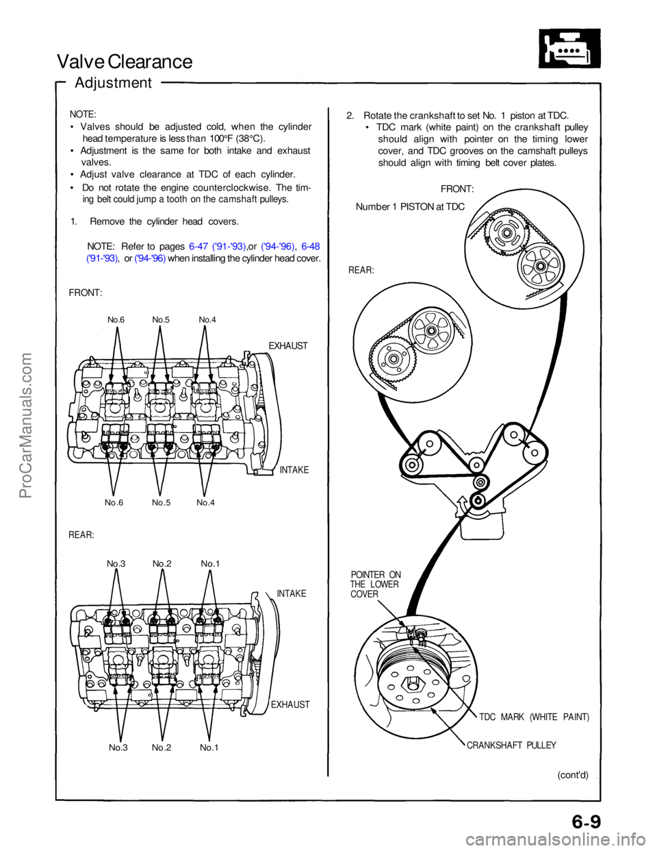
Valve Clearance
Adjustment
NOTE:
Valves should be adjusted cold, when the cylinderhead temperature is less than 100°F (38°C).
Adjustment is the same for both intake and exhaust valves.
Adjust valve clearance at TDC of each cylinder.
Do not rotate the engine counterclockwise. The tim-
ing belt could jump a tooth on the camshaft pulleys.
1. Remove the cylinder head covers.
NOTE: Refer to pages 6-47 ('91-'93),or ('94-'96), 6-48
('91-'93), or ('94-'96) when installing the cylinder head cover.
FRONT:
No.6 No.5 No.4
EXHAUST
INTAKE
No.6 No.5 No.4
REAR:
No.3 No.2 No.1
INTAKE
EXHAUST
No.3 No.2 No.1 (cont'd)
CRANKSHAFT PULLEY
TDC MARK (WHITE PAINT)
POINTER ON
THE LOWER
COVER
REAR:
Number 1 PISTON at TDC
FRONT:
2. Rotate the crankshaft to set No. 1 piston at TDC.
TDC mark (white paint) on the crankshaft pulley
should align with pointer on the timing lower
cover, and TDC grooves on the camshaft pulleysshould align with timing belt cover plates.ProCarManuals.com
Page 88 of 1640
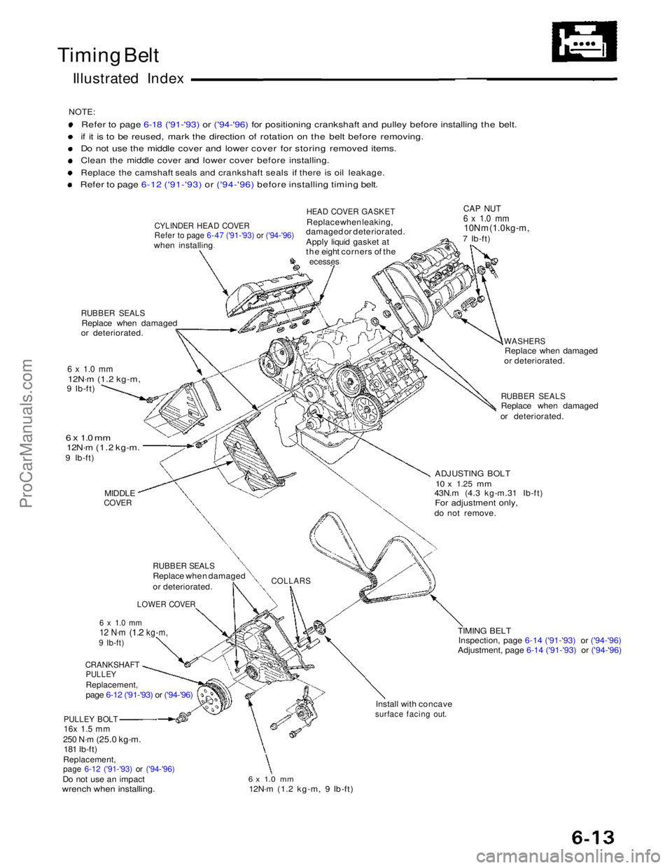
Timing Belt
Illustrated Index
NOTE:
Refer to page 6-18 ('91-'93) or ('94-'96) for positioning crankshaft and pulley before installing the belt.
if it is to be reused, mark the direction of rotation on the belt before removing.
Do not use the middle cover and lower cover for storing removed items.
Clean the middle cover and lower cover before installing.
Replace the camshaft seals and crankshaft seals if there is oil leakage.
Refer to page 6-12 ('91-'93) or ('94-'96) before installing timing belt.
CYLINDER HEAD COVER
Refer to page 6-47 ('91-'93) or ('94-'96)
when installing
RUBBER SEALS
Replace when damaged
or deteriorated.
6 x 1.0 mm
12N·m (1.2 kg-m,
9 Ib-ft)
6 x 1.0 mm
12N·m (1.2 kg-m.
9 Ib-ft)
MIDDLE
COVER
RUBBER SEALS
Replace when damaged
or deteriorated.
LOWER COVER
6 x 1.0 mm
12 N·m
(1.2
kg-m,
9 Ib-ft)
CRANKSHAFT
PULLEY
Replacement,
page 6-12 ('91-'93) or ('94-'96)
PULLEY BOLT
16x 1.5 mm
250 N·m
(25.0 kg-m. 181 Ib-ft)
Replacement,
page 6-12 ('91-'93)
or ('94-'96)
Do not use an impact
wrench when installing.
HEAD COVER GASKET
Replace when leaking,
damaged or deteriorated.
Apply liquid gasket at
the eight corners of the
ecesses
CAP NUT
6 x 1.0 mm
10N m (1.0 kg-m,
7 Ib-ft)
WASHERS
Replace when damaged
or deteriorated.
RUBBER SEALS
Replace when damaged
or deteriorated.
ADJUSTING BOLT
10 x
1.25
mm
43N.m (4.3 kg-m.31 Ib-ft)
For adjustment only,
do not remove.
COLLARS
TIMING BELTInspection, page 6-14 ('91-'93) or ('94-'96)
Adjustment, page 6-14 ('91-'93) or ('94-'96)
Install with concave
surface facing out.
6 x 1.0 mm
12N·m (1.2 kg-m, 9 Ib-ft)ProCarManuals.com