brake sensor ACURA NSX 1991 Service Repair Manual
[x] Cancel search | Manufacturer: ACURA, Model Year: 1991, Model line: NSX, Model: ACURA NSX 1991Pages: 1640, PDF Size: 60.48 MB
Page 306 of 1640
Transmission Assembly
Removal
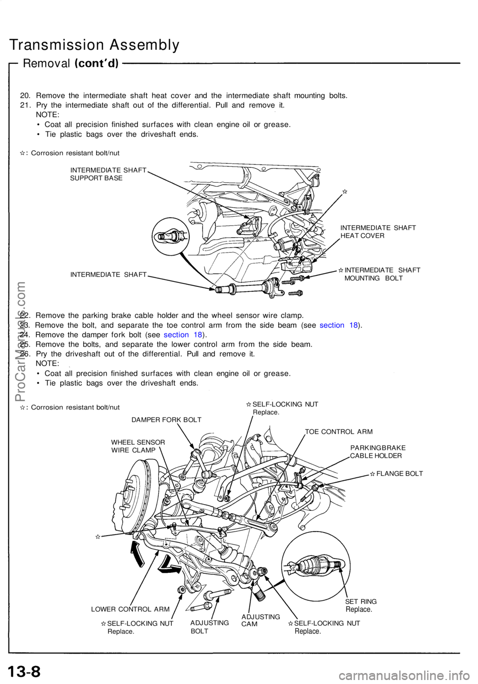
20. Remove the intermediate shaft heat cover and the intermediate shaft mounting bolts.
21. Pry the intermediate shaft out of the differential. Pull and remove it. NOTE:
• Coat all precision finished surfaces with clean engine oil or grease.
• Tie plastic bags over the driveshaft ends.
Corrosion resistant bolt/nut
INTERMEDIATE SHAFT
SUPPORT BASE
INTERMEDIATE SHAFT INTERMEDIATE SHAFT
HEAT COVER
INTERMEDIATE SHAFT
MOUNTING BOLT
22. Remove the parking brake cable holder and the wheel sensor wire clamp.
23. Remove the bolt, and separate the toe control arm from the side beam (see section 18).
24. Remove the damper fork bolt (see section 18).
25. Remove the bolts, and separate the lower control arm from the side beam. 26. Pry the driveshaft out of the differential. Pull and remove it. NOTE:
• Coat all precision finished surfaces with clean engine oil or grease.
• Tie plastic bags over the driveshaft ends.
Corrosion resistant bolt/nut
DAMPER FORK BOLT SELF-LOCKING NUT
Replace.
TOE CONTROL ARM
WHEEL SENSOR WIRE CLAMP PARKING BRAKE
CABLE HOLDER
FLANGE BOLT
LOWER CONTROL ARM SELF-LOCKING NUTReplace. ADJUSTING
BOLT
ADJUSTING
CAM
SELF-LOCKING NUT
Replace.
SET RING
Replace.ProCarManuals.com
Page 492 of 1640
Illustrated Index
The accumulator contains high-pressure nitrogen gas; do not puncture, expose to flame or attempt to
disassemble the accumulator or it may explode; severe personal injury may result.
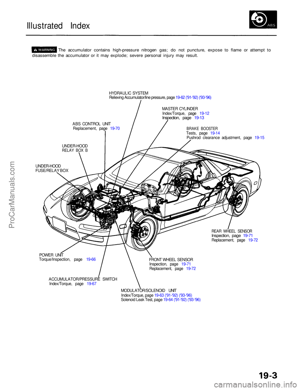
HYDRAULIC SYSTEM
Relieving Accumulator/line pressure, page 19-62 ('91-'92) ('93-'96)
MASTER CYLINDER
Index/Torque, page 19-12
Inspection, page 19-13
ABS CONTROL UNIT Replacement, page 19-70
BRAKE BOOSTER
Tests, page 19-14 Pushrod clearance adjustment, page 19-15
UNDER-HOOD
RELAY BOX B
UNDER-HOOD
FUSE/RELAY BOX
REAR WHEEL SENSOR
Inspection, page 19-71
Replacement, page 19-72
POWER UNIT
Torque/Inspection, page 19-66
ACCUMULATOR/PRESSURE SWITCHIndex/Torque, page 19-67 FRONT WHEEL SENSOR
Inspection, page 19-71
Replacement, page 19-72
MODULATOR/SOLENOID UNIT
Index/Torque, page 19-63 ('91-'92) ('93-'96)
Solenoid Leak Test, page 19-64 ('91-'92) ('93-'96)
ProCarManuals.com
Page 517 of 1640
Anti-lock Brake System (ABS) Description
Features/Construction/Operation
General
In a conventional brake system, if the brake pedal is depressed excessively, the wheels can lock before the vehicle
comes to a stop. In such a case, the stability of the vehicle is reduced if the rear wheels are locked, and maneuverabily of
the vehicle is reduced if the front wheels are locked, creating an extremely unstable condition.
The Anti-lock Brake System (ABS) modulates the pressure of the brake fluid applied to each caliper, thereby preventing
the locking of the wheels, whenever the wheels are likely to be locked due to excessive braking. It then restores normal
hydraulic pressure when there is no longer any possibility of wheel locking.
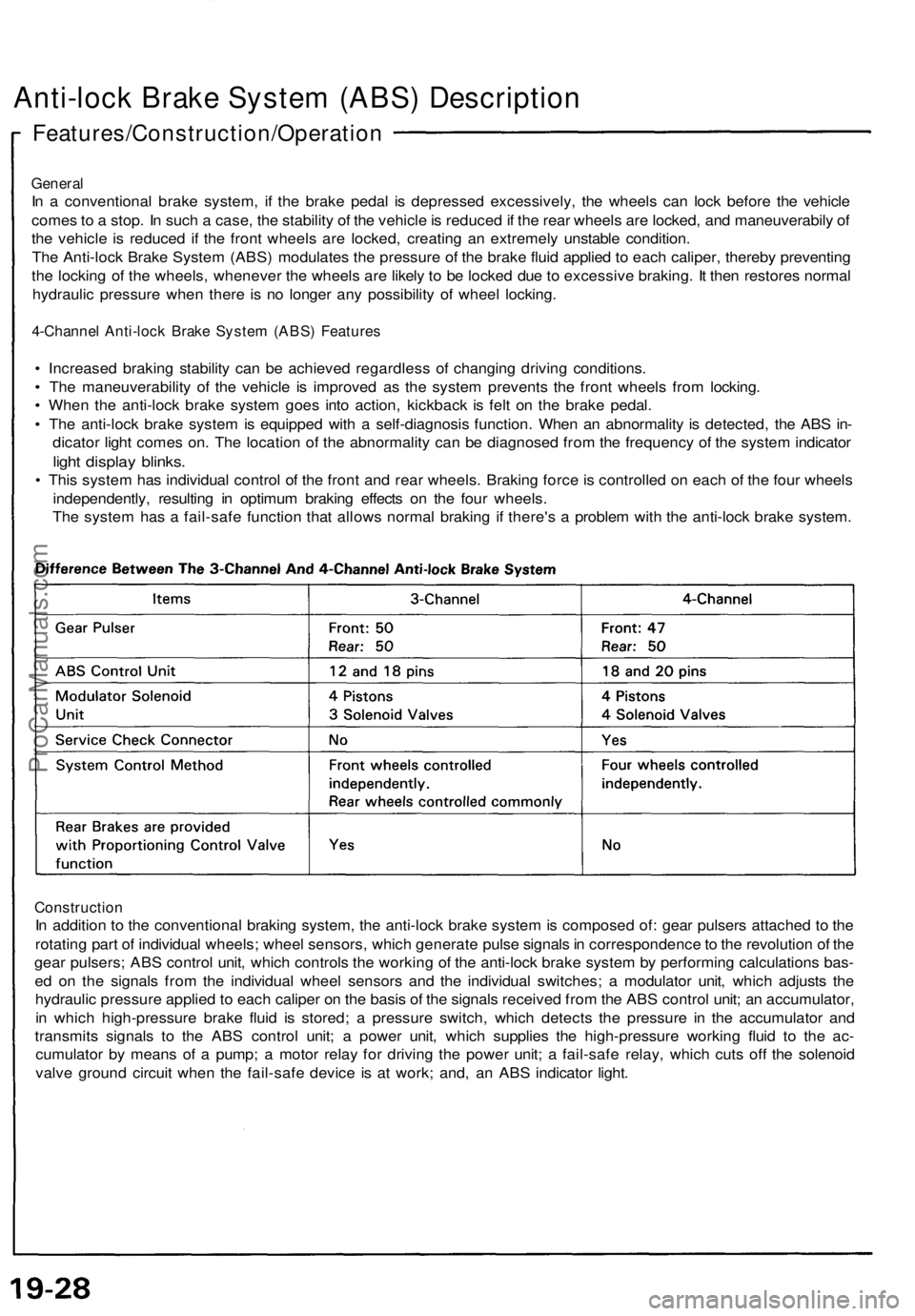
4-Channel Anti-lock Brake System (ABS) Features
• Increased braking stability can be achieved regardless of changing driving conditions.
• The maneuverability of the vehicle is improved as the system prevents the front wheels from locking.
• When the anti-lock brake system goes into action, kickback is felt on the brake pedal.
• The anti-lock brake system is equipped with a self-diagnosis function. When an abnormality is detected, the ABS in-
dicator light comes on. The location of the abnormality can be diagnosed from the frequency of the system indicator
light display blinks.
• This system has individual control of the front and rear wheels. Braking force is controlled on each of the four wheels
independently, resulting in optimum braking effects on the four wheels.
The system has a fail-safe function that allows normal braking if there's a problem with the anti-lock brake system.
Construction
In addition to the conventional braking system, the anti-lock brake system is composed of: gear pulsers attached to the
rotating part of individual wheels; wheel sensors, which generate pulse signals in correspondence to the revolution of the
gear pulsers; ABS control unit, which controls the working of the anti-lock brake system by performing calculations bas-
ed on the signals from the individual wheel sensors and the individual switches; a modulator unit, which adjusts the
hydraulic pressure applied to each caliper on the basis of the signals received from the ABS control unit; an accumulator,
in which high-pressure brake fluid is stored; a pressure switch, which detects the pressure in the accumulator and
transmits signals to the ABS control unit; a power unit, which supplies the high-pressure working fluid to the ac-
cumulator by means of a pump; a motor relay for driving the power unit; a fail-safe relay, which cuts off the solenoid
valve ground circuit when the fail-safe device is at work; and, an ABS indicator light.ProCarManuals.com
Page 521 of 1640
Anti-lock Brake System (ABS) Description
Features/Construction/Operation (cont'd)
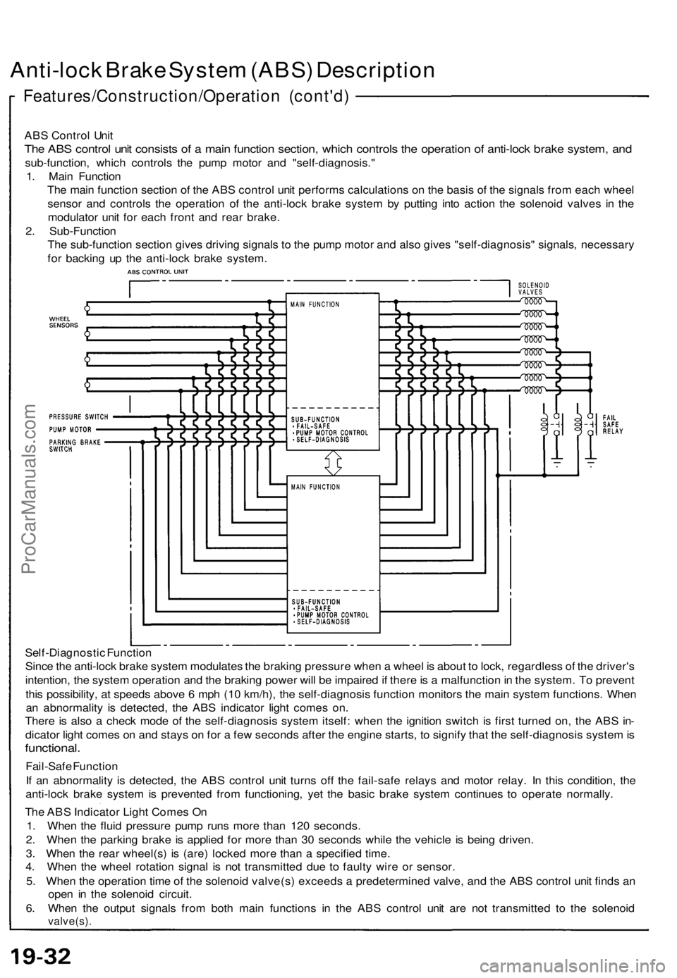
ABS Control Unit
The ABS control unit consists of a main function section, which controls the operation of anti-lock brake system, and
sub-function, which controls the pump motor and "self-diagnosis."
1. Main Function
The main function section of the ABS control unit performs calculations on the basis of the signals from each wheel
sensor and controls the operation of the anti-lock brake system by putting into action the solenoid valves in the
modulator unit for each front and rear brake.
2. Sub-Function
The sub-function section gives driving signals to the pump motor and also gives "self-diagnosis" signals, necessary
for backing up the anti-lock brake system.
Self-Diagnostic Function
Since the anti-lock brake system modulates the braking pressure when a wheel is about to lock, regardless of the driver's
intention, the system operation and the braking power will be impaired if there is a malfunction in the system. To prevent
this possibility, at speeds above 6 mph (10 km/h), the self-diagnosis function monitors the main system functions. When
an abnormality is detected, the ABS indicator light comes on.
There is also a check mode of the self-diagnosis system itself: when the ignition switch is first turned on, the ABS in-
dicator light comes on and stays on for a few seconds after the engine starts, to signify that the self-diagnosis system is
functional.
Fail-Safe Function
If an abnormality is detected, the ABS control unit turns off the fail-safe relays and motor relay. In this condition, the
anti-lock brake system is prevented from functioning, yet the basic brake system continues to operate normally.
The ABS Indicator Light Comes On
1. When the fluid pressure pump runs more than 120 seconds.
2. When the parking brake is applied for more than 30 seconds while the vehicle is being driven.
3. When the rear wheel(s) is (are) locked more than a specified time.
4. When the wheel rotation signal is not transmitted due to faulty wire or sensor.
5. When the operation time of the solenoid valve(s) exceeds a predetermined valve, and the ABS control unit finds an
open in the solenoid circuit.
6. When the output signals from both main functions in the ABS control unit are not transmitted to the solenoid
valve(s).ProCarManuals.com
Page 527 of 1640
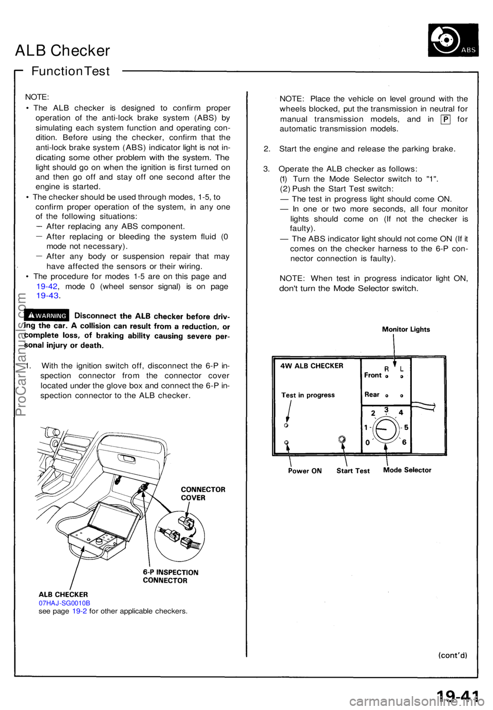
ALB Checke r
Function Tes t
NOTE :
• Th e AL B checke r i s designe d t o confir m prope r
operatio n of the anti-loc k brak e syste m (ABS ) b y
simulatin g eac h syste m functio n an d operatin g con -
dition . Befor e usin g th e checker , confir m tha t th e
anti-loc k brak e syste m (ABS ) indicato r ligh t i s no t in -
dicatin g som e othe r proble m wit h th e system . Th e
light shoul d g o o n whe n th e ignitio n i s firs t turne d o n
an d the n g o of f an d sta y of f on e secon d afte r th e
engin e i s started .
• Th e checke r shoul d b e use d throug h modes ,
1-5, t o
confir m prope r operatio n of the system , i n an y on e
of th e followin g situations :
Afte r replacin g an y AB S component .
Afte r replacin g o r bleedin g th e syste m flui d ( 0
mod e no t necessary) .
Afte r an y bod y o r suspensio n repai r tha t ma y
hav e affecte d th e sensor s o r thei r wiring .
• Th e procedur e fo r mode s
1-5 ar e o n thi s pag e an d
19-42 , mod e 0 (whee l senso r signal ) i s o n pag e
19-43 .
1. Wit h th e ignitio n switc h off , disconnec t th e 6- P in -
spectio n connecto r fro m th e connecto r cove r
locate d unde r th e glov e bo x an d connec t th e 6- P in -
spectio n connecto r t o th e AL B checker .
07HAJ-SG0010Bsee pag e 19- 2 fo r othe r applicabl e checkers .
NOTE: Plac e th e vehicl e o n leve l ground with th e
wheel s blocked , pu t th e transmissio n i n neutra l fo r
manua l transmissio n models , an d i n fo r
automati c transmissio n models .
2 . Star t th e engin e an d releas e th e parkin g brake .
3 . Operat e th e AL B checke r a s follows :
(1 ) Tur n th e Mod e Selecto r switc h t o "1" .
(2 ) Pus h th e Star t Tes t switch :
— Th e tes t i n progres s ligh t shoul d com e ON .
— In on e o r tw o mor e seconds , al l fou r monito r
light s shoul d com e o n (I f no t th e checke r i s
faulty) .
— Th e AB S indicato r ligh t shoul d no t com e O N (I f i t
come s o n th e checke r harnes s t o th e 6- P con -
necto r connectio n i s faulty) .
NOTE : Whe n tes t i n progres s indicato r ligh t ON ,
don't tur n th e Mod e Selecto r switch .
ProCarManuals.com
Page 805 of 1640
Safety Indicator
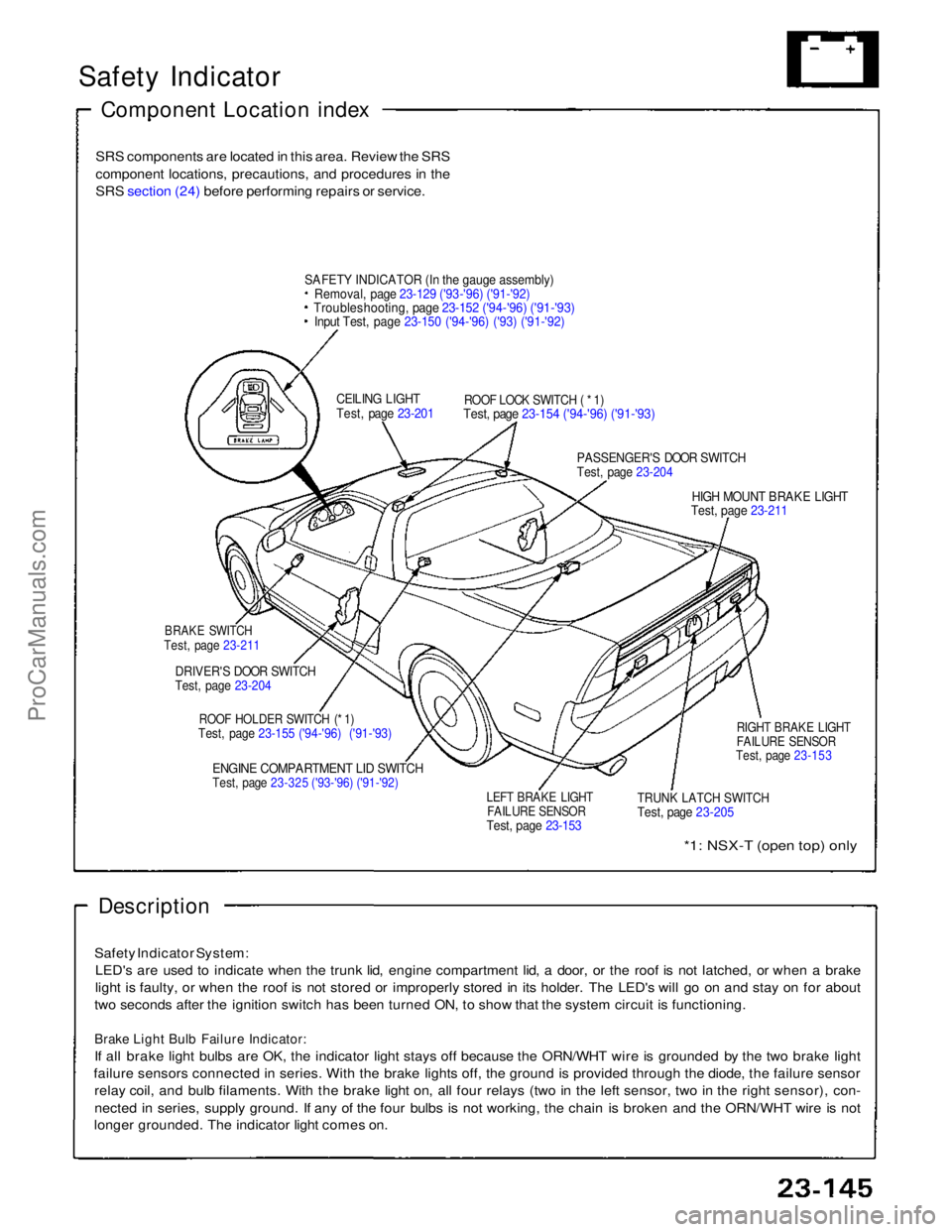
Component Location index
SRS components are located in this area. Review the SRS
component locations, precautions, and procedures in the
SRS section (24) before performing repairs or service.
SAFET
Y
INDICATOR (In the gauge assembly)
Removal, page 23-129 ('93-'96) ('91-'92)
Troubleshooting, page 23-152 ('94-'96) ('91-'93)
Input Test, page 23-150 ('94-'96) ('93) ('91-'92)
CEILING LIGHT
Test, page 23-201
ROOF LOCK SWITCH ( * 1)
Test, page 23-154 ('94-'96) ('91-'93)
PASSENGER'S DOOR SWITCH
Test, page 23-204
HIGH MOUNT BRAKE LIGHT
Test, page 23-211
BRAKE SWITCH
Test, page 23-211
DRIVER'S DOOR SWITCH
Test, page 23-204
ROOF HOLDER SWITCH (* 1)
Test, page 23-155 ('94-'96) ('91-'93)
ENGINE COMPARTMENT LID SWITCH
Test, page 23-325 ('93-'96) ('91-'92)
LEFT BRAKE LIGHT
FAILURE SENSOR
Test, page 23-153
TRUNK LATCH SWITCH
Test, page 23-205
RIGHT BRAKE LIGHT
FAILURE SENSOR
Test, page 23-153
*1: NSX-T (open top) only
Description
Safety Indicator System: LED's are used to indicate when the trunk lid, engine compartment lid, a door, or the roof is not latched, or when a brake
light is faulty, or when the roof is not stored or improperly stored in its holder. The LED's will go on and stay on for about
two seconds after the ignition switch has been turned ON, to show that the system circuit is functioning.
Brake Light Bulb Failure Indicator:
If all brake light bulbs are OK, the indicator light stays off because the ORN/WHT wire is grounded by the two brake light
failure sensors connected in series. With the brake lights off, the ground is provided through the diode, the failure sensor relay coil, and bulb filaments. With the brake light on, all four relays (two in the left sensor, two in the right sensor), con-
nected in series, supply ground. If any of the four bulbs is not working, the chain is broken and the ORN/WHT wire is not
longer grounded. The indicator light comes on.ProCarManuals.com
Page 809 of 1640
Brake Ligh t Failur e Senso r Tes t
1. Firs t mak e sur e th e brak e light s com e o n whe n th e
brak e peda l i s pressed .
• I f al l th e brak e light s com e on , g o t o ste p 2 .
• I f on e o f th e brak e light s doe s no t com e on , chec k
whethe r th e bul b is blown . I f th e bul b is OK , g o
to ste p 2 .
• I f non e of the brak e light s com e on , chec k th e
brak e ligh t circui t.
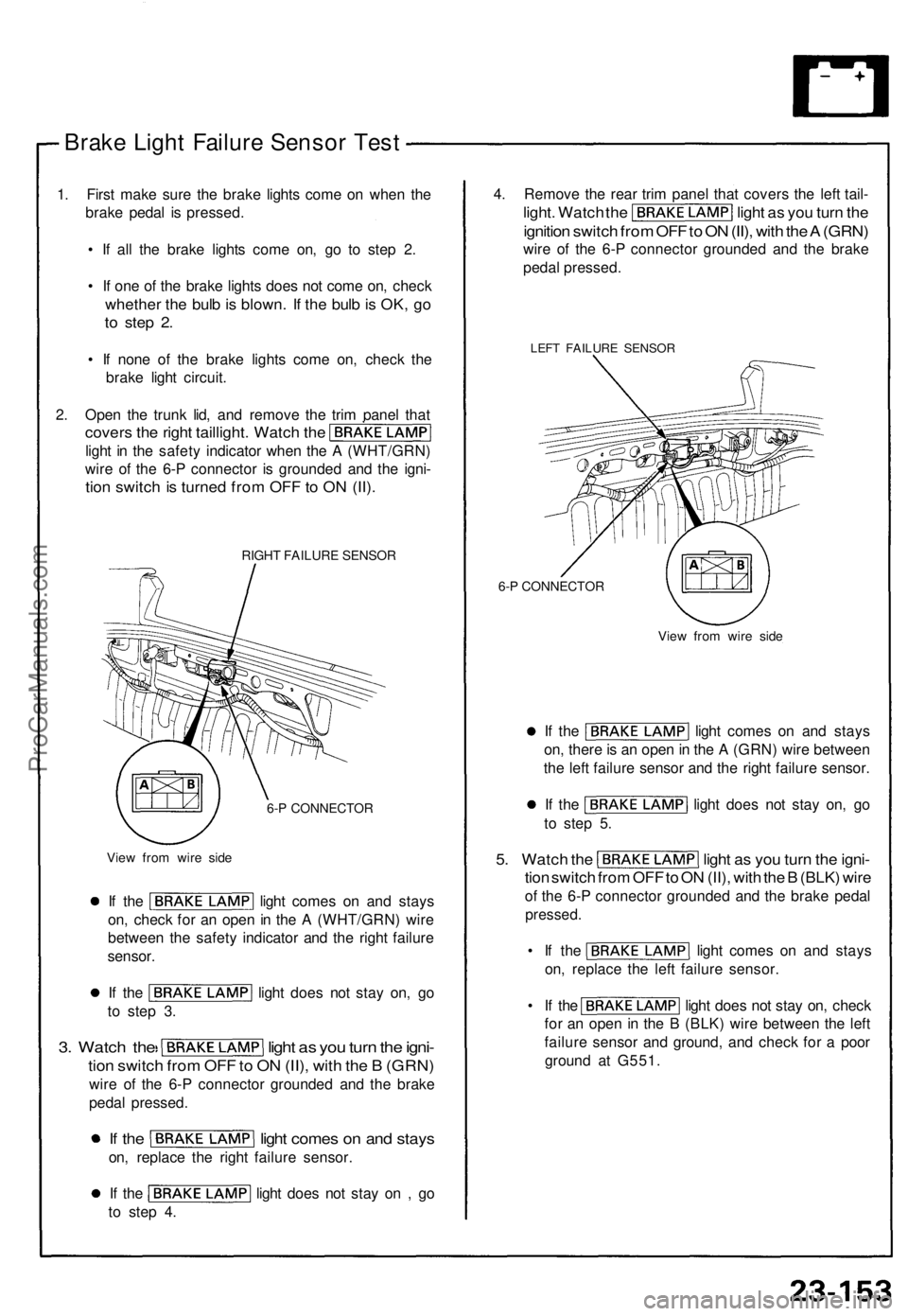
2 . Ope n th e trun k lid , an d remov e th e tri m pane l tha t
cover s th e righ t taillight . Watc h th e
ligh t i n th e safet y indicato r whe n th e A (WHT/GRN )
wir e o f th e 6- P connecto r i s grounde d an d th e igni -
tion switc h is turne d fro m OF F to O N (II) .
RIGH T FAILUR E SENSO R
6- P CONNECTO R
Vie w fro m wir e sid e
If th e ligh t come s o n an d stay s
on , chec k fo r a n ope n in th e A (WHT/GRN ) wir e
betwee n th e safet y indicato r an d th e righ t failur e
sensor .
If th e ligh t doe s no t sta y on , g o
t o ste p 3 .
3. Watc h th e ligh t a s yo u tur n th e igni -
tion switc h fro m OF F to O N (II) , wit h th e B (GRN )
wire o f th e 6- P connecto r grounde d an d th e brak e
peda l pressed .
If th e ligh t come s o n an d stay s
on, replac e th e righ t failur e sensor .
If th e ligh t doe s no t sta y o n , g o
t o ste p 4 . 4
. Remov e th e rea r tri m pane l tha t cover s th e lef t tail -
light . Watc h th e ligh t a s yo u tur n th e
ignitio n switc h fro m OF F to O N (II) , wit h th e A (GRN )
wire o f th e 6- P connecto r grounde d an d th e brak e
peda l pressed .
LEFT FAILUR E SENSO R
6-P CONNECTO R
View fro m wir e sid e
If th e ligh t come s o n an d stay s
on , ther e is a n ope n in th e A (GRN ) wir e betwee n
th e lef t failur e senso r an d th e righ t failur e sensor .
If th e ligh t doe s no t sta y on , g o
t o ste p 5 .
5. Watc h th e ligh t a s yo u tur n th e igni -
tion switc h fro m OF F to O N (II) , wit h th e B (BLK ) wir e
of th e 6- P connecto r grounde d an d th e brak e peda l
pressed .
• I f th e ligh t come s o n an d stay s
on , replac e th e lef t failur e sensor .
• I f th e ligh t doe s no t sta y on , chec k
fo r a n ope n in th e B (BLK ) wir e betwee n th e lef t
failur e senso r an d ground , an d chec k fo r a poo r
groun d a t G551 .
ProCarManuals.com
Page 859 of 1640
Brake Lights
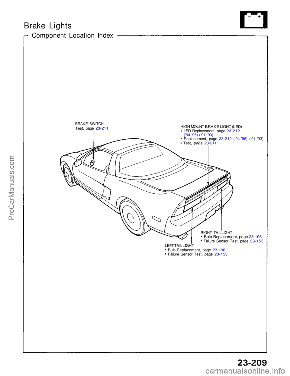
Component Location Index
BRAKE SWITCH
Test, page 23-211
HIGH MOUNT BRAKE LIGHT (LED)
LED Replacement, page 23-212
('94-'96) ('91-'93)
Replacement, page 23-212 ('94-'96) ('91-'93) Test, page 23-211
RIGHT TAILLIGHT
Bul
b
Replacement, page 23-196
Failure Sensor Test, page 23-153
LEFT TAILLIGHT Bulb Replacement, page 23-196 Failure Sensor Test, page 23-153
ProCarManuals.com
Page 860 of 1640
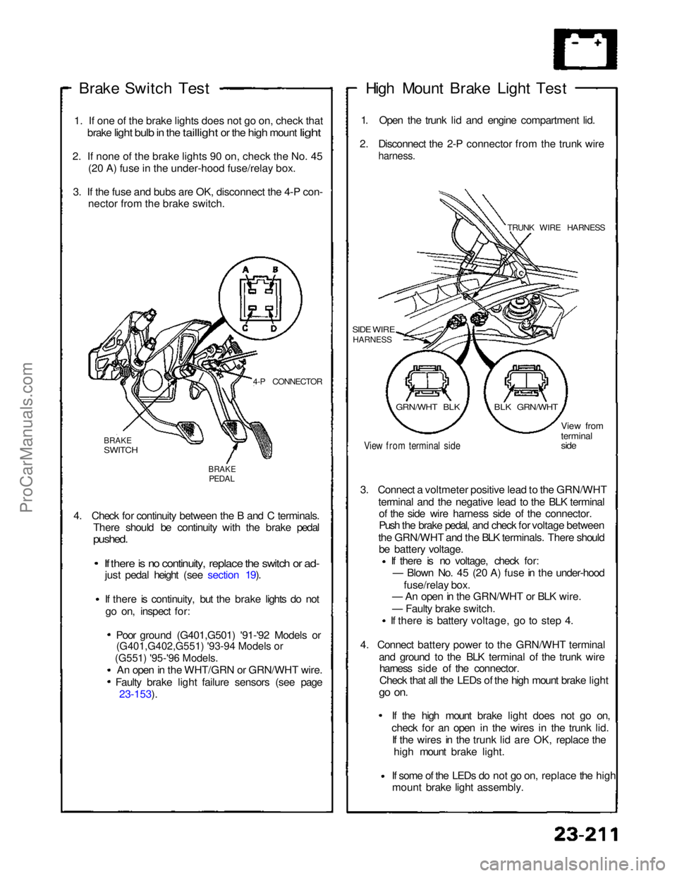
(G551) '95-'96 Models.
(G401,G402,G551) '93-94 Models or
Brake Switch
Test
1
.
If one of the brake lights does not go on, check that
brake
light bulb in the taillight or the high mount light
2
.
If none of the brake lights 90 on, check the No. 45 (2
0
A) fuse in the under-hood fuse/relay box.
3
.
If the fuse and bubs are OK, disconnect the 4-P con- necto
r
from the brake switch.
4-P CONNECTOR
BRAKE
SWITCH
BRAKE
PEDAL
4. Check for continuity between the B and C terminals. There should be continuity with the brake pedal
pushed.
If there is no continuity, replace the switch or ad-
just pedal height (see section 19).
If there is continuity, but the brake lights do not
go on, inspect for:
Poor ground (G401,G501) '91-'92 Models or
An open in the WHT/GRN or GRN/WHT wire. Faulty brake light failure sensors (see page 23-153). High Mount Brake Light Test
1. Open the trunk lid and engine compartment lid.
2. Disconnect the 2-P connector from the trunk wire
harness.
TRUNK WIRE HARNESS
SIDE WIRE
HARNESS
View from terminal side
View from
terminal
side
3. Connect a voltmeter positive lead to the GRN/WHT terminal and the negative lead to the BLK terminalof the side wire harness side of the connector.
Push the brake pedal, and check for voltage between
the GRN/WHT and the BLK terminals. There should be battery voltage. If there is no voltage, check for:
— Blown No. 45 (20 A) fuse in the under-hood
fuse/relay box.
— An open in the GRN/WHT or BLK wire.
— Faulty brake switch.
If there is battery voltage, go to step 4.
4. Connect battery power to the GRN/WHT terminal and ground to the BLK terminal of the trunk wireharness side of the connector.
Check that all the LEDs of the high mount brake light
go on.
If the high mount brake light does not go on,check for an open in the wires
in the trunk lid.
If the wires in the trunk lid are OK, replace the
high mount brake light.
If some of the LEDs do not go on,
replace the high
mount brake light assembly.
GRN/WHT BLK
BLK GRN/WHTProCarManuals.com
Page 935 of 1640
Cruise Control
Description
The cruise control system uses mechanically and electri-
cally operated devices to maintain vehicle speed at a
setting selected by the driver.
The ECM receives command signals from the cruise con-
trol main switch and the cruise control set/resume switch.
It receives information about operating conditions from
the brake switch, vehicle speed sensor (VSS), the clutch
switch (with manual transmission), or the A/T gear posi-
tion switch (with automatic transmission). The ECM
sends operational signals to the devices that regulate the
throttle position. The throttle position maintains the
selected vehicle speed. Essentially, the ECM compares
the actual speed of the vehicle to the selected speed.
Then, it uses the result of that comparison to open or
close the throttle.
The brake switch releases the system's control of the
throttle at the instant the driver depresses the brake
pedal. The switch sends an electronic signal to the ECM
when the brake pedal is depressed; the ECM responds
by allowing the throttle to close. The clutch switch (man-
ual transmission) or the A/T gear position switch (auto-
matic transmission) sends a disengage signal to the
ECM that also allows the throttle to close.
Operation:
The cruise control system will set and automatically
maintain any speed above 25 mph (45 km/h). To set,
make sure that the main switch is in the "ON" position.
After reaching the desired speed, press the set switch.
The ECM will receive a set signal and, in turn, will actu-
ate the throttle valve control motor. When the set switch
is depressed and the cruise control system is on, the
"cruise control" ON indicator in the gauge assembly will
light up. You can cancel the cruise control system by
pushing the main switch to "OFF". This erases the set
speed from memory. If the system is disengaged tem-
porarily by the brake switch, clutch switch, or A/T gear
position switch and vehicle speed is still above 25 mph,
press the resume switch. With the resume switch
depressed and the set memory retained, the vehicle
automatically returns to the previous set speed.
For gradual acceleration without depressing the acceler-
ator pedal, push the resume switch down and hold it
there until the desired speed is reached. This will send
an acceleration signal to the ECM. When the switch is
released, the system will be reprogrammed for the new
speed. To slow down, depress the set switch. This will
send a deceleration signal to the ECM causing the car to
coast until the desired speed is reached. When the
desired speed is reached, release the set switch. This
will reprogram the system for the new speed.ProCarManuals.com