bulb ACURA NSX 1991 Service Repair Manual
[x] Cancel search | Manufacturer: ACURA, Model Year: 1991, Model line: NSX, Model: ACURA NSX 1991Pages: 1640, PDF Size: 60.48 MB
Page 230 of 1640
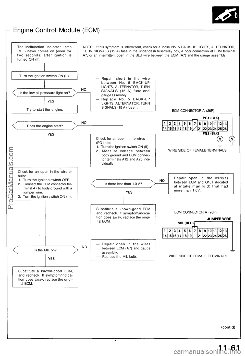
Engine Control Module (ECM)
NOTE: If this symptom is intermittent, check for a loose No. 5 BACK-UP LIGHTS, ALTERNATOR,
TURN SIGNALS (15 A) fuse in the under-dash fuse/relay box, a poor connection at ECM terminal
A7, or an intermittent open in the BLU wire between the ECM (A7) and the gauge assembly.
Is the low oil pressure light on?
Try to start the engine.
Does the engine start?
Check for an open in the wire or
bulb:
1. Turn the ignition switch OFF.
2. Connect the ECM connector ter-
minal A7 to body ground with a
jumper wire.
3. Turn the ignition switch ON (II).
Is the MIL on?
Substitute a known-good ECM,
and recheck. If symptom/indica-
tion goes away, replace the origi-
nal
ECM.
— Repair short in the wire
between No. 5 BACK-UP
LIGHTS, ALTERNATOR, TURN
SIGNALS (15 A) fuse and
gauge assembly.
— Replace No. 5 BACK-UP
LIGHTS, ALTERNATOR, TURN
SIGNALS (15 A) fuse.
ECM CONNECTOR A (26P)
Check for an open in the wires
(PG line):
1. Turn the ignition switch ON (II).
2. Measure voltage between
body ground and ECM connec-
tor terminals A12 and A25 indi-
vidually.
WIRE SIDE OF FEMALE TERMINALS
Is there less than 1.0 V?
Repair open in the wire(s)
between ECM and G101 (located
at intake manifold) that had
more than 1.0V.
— Repair open in the wires
between ECM (A7) and gauge
assembly.
— Replace the MIL bulb.
WIRE SIDE OF FEMALE TERMINALS
ECM CONNECTOR A (26P)
Substitute a known-good ECM
and recheck. If symptom/indica-
tion goes away, replace the origi-
nal
ECM.
Turn the ignition switch ON (II).
The Malfunction Indicator Lamp
(MIL) never comes on (even for
two seconds) after ignition is
turned ON (II).ProCarManuals.com
Page 420 of 1640
Troubleshooting Precautions
EPS Indicator Light
Under normal conditions, the EPS indicator light in the gauge assembly comes on when the ignition switch is turned to
the ON (II) position, then goes off after the engine is started. This indicates that the bulb and its circuits are operating cor-
rectly. If there is any trouble in the system, the EPS indicator light turns on during driving, and the power steering assist is
turned off. When the EPS indicator light comes on, the control unit memorizes the DTC. In this case, the control unit does
not activate the EPS system after the engine starts again but it keeps the EPS indicator light on.
Diagnostic Trouble Code (DTC)
• The lowest DTC is indicated first.
• The DTCs continue blinking until the ignition switch is turned off.
• The DTCs are erased from the control unit when the EPS control unit VBU power supply or connector is disconnected.
• The EPS system can be reset and the control unit's memory can be erased by disconnecting the CLOCK (7.5 A) fuse for
more than ten seconds.
Self-diagnosis:
The CPU (central processing unit) controls the following when it detects a problem during self-diagnosis:
1. Turns the EPS indicator light ON to alert the driver.
2. Power assist stops, and normal manual steering operation resumes (except DTC 21 and DTC 33).
3. The EPS control unit memorizes the diagnostic trouble code (DTC).
4. After the DTC is stored in the control unit, the CPU stops self-diagnosis.
Troubleshooting:
• Before starting the troubleshooting, clear the DTC by disconnecting the CLOCK (7.5 A) fuse for ten seconds or more,
and test-drive the car. Check that the symptom of the trouble appears again, and then troubleshoot. If the problem is an
intermittent problem, the system does not become active after the engine starts even though the problem is solved.
• When both EPS indicator light and A/T "D" indicator light come on, perform the A/T troubleshooting first.
• When the customer's reported problem cannot be verified in the car, ask the customer about the conditions when the
EPS indicator light came ON, then test-drive the car under those conditions, if possible. If the EPS indicator light does
not come ON during the test, check for loose connections or poor contacts at the connectors by wiggling the harness,
etc.
• The connector terminal numbers are viewed from the wire side for the female terminals and from the terminal side for
the male terminals.
• After the repair, test-drive the car and check that the EPS indicator light does not come ON again during the test. (Refer
to the Symptom-to-System Chart for diagnostic period.)ProCarManuals.com
Page 530 of 1640
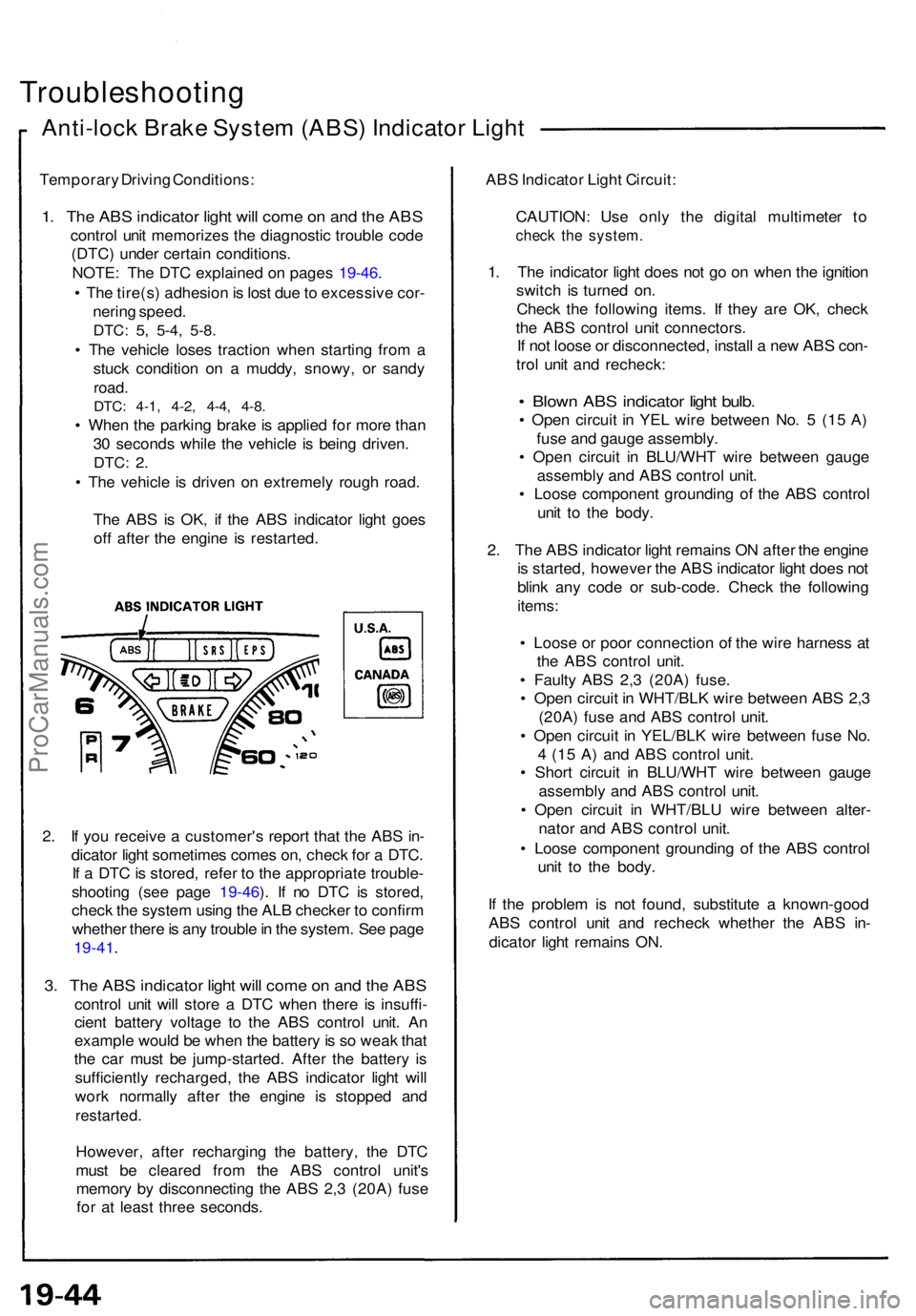
Troubleshooting
Anti-lock Brak e Syste m (ABS ) Indicato r Ligh t
Temporar y Drivin g Conditions :
1. Th e AB S indicato r ligh t wil l com e o n an d th e AB S
contro l uni t memorize s th e diagnosti c troubl e cod e
(DTC ) unde r certai n conditions .
NOTE : Th e DT C explaine d o n page s 19-46 .
• Th e tire(s ) adhesio n is los t du e to excessiv e cor -
nerin g speed .
DTC: 5, 5-4 , 5-8 .
• Th e vehicl e lose s tractio n whe n startin g fro m a
stuc k conditio n o n a muddy , snowy , o r sand y
road.
DTC: 4-1 , 4-2 , 4-4 , 4-8 .
• Whe n th e parkin g brak e is applie d fo r mor e tha n
3 0 second s whil e th e vehicl e i s bein g driven .
DTC: 2.
• Th e vehicl e is drive n o n extremel y roug h road .
Th e AB S is OK , i f th e AB S indicato r ligh t goe s
of f afte r th e engin e i s restarted .
2 . I f yo u receiv e a customer' s repor t tha t th e AB S in -
dicato r ligh t sometime s come s on , chec k fo r a DTC .
I f a DT C is stored , refe r t o th e appropriat e trouble -
shootin g (se e pag e 19-46 ). I f n o DT C is stored ,
chec k th e syste m usin g th e AL B checke r t o confir m
whethe r ther e is an y troubl e in th e system . Se e pag e
19-41 .
3. Th e AB S indicato r ligh t wil l com e o n an d th e AB S
contro l uni t wil l stor e a DT C whe n ther e i s insuffi -
cien t batter y voltag e t o th e AB S contro l unit . A n
exampl e woul d b e whe n th e batter y is s o wea k tha t
th e ca r mus t b e jump-started . Afte r th e batter y i s
sufficientl y recharged , th e AB S indicato r ligh t wil l
wor k normall y afte r th e engin e i s stoppe d an d
restarted .
However , afte r rechargin g th e battery , th e DT C
mus t b e cleare d fro m th e AB S contro l unit' s
memor y b y disconnectin g th e AB S 2, 3 (20A ) fus e
fo r a t leas t thre e seconds . AB
S Indicato r Ligh t Circuit :
CAUTION : Us e onl y th e digita l multimete r t o
chec k th e system .
1. Th e indicato r ligh t doe s no t g o o n whe n th e ignitio n
switc h i s turne d on .
Chec k th e followin g items . I f the y ar e OK , chec k
th e AB S contro l uni t connectors .
I f no t loos e o r disconnected , instal l a ne w AB S con -
tro l uni t an d recheck :
• Blow n AB S indicato r ligh t bulb .
• Ope n circui t i n YE L wir e betwee n No . 5 (1 5 A )
fus e an d gaug e assembly .
• Ope n circui t i n BLU/WH T wir e betwee n gaug e
assembl y an d AB S contro l unit .
• Loos e componen t groundin g of the AB S contro l
uni t t o th e body .
2 . Th e AB S indicato r ligh t remain s O N afte r th e engin e
i s started , howeve r th e AB S indicato r ligh t doe s no t
blin k an y cod e o r sub-code . Chec k th e followin g
items :
• Loos e o r poo r connectio n of the wir e harnes s a t
th e AB S contro l unit .
• Fault y AB S 2, 3 (20A ) fuse .
• Ope n circui t i n WHT/BL K wir e betwee n AB S 2, 3
(20A ) fus e an d AB S contro l unit .
• Ope n circui t i n YEL/BL K wir e betwee n fus e No .
4 (1 5 A ) an d AB S contro l unit .
• Shor t circui t i n BLU/WH T wir e betwee n gaug e
assembl y an d AB S contro l unit .
• Ope n circui t i n WHT/BL U wir e betwee n alter -
nato r an d AB S contro l unit .
• Loos e componen t groundin g o f th e AB S contro l
uni t t o th e body .
I f th e proble m is no t found , substitut e a known-goo d
AB S contro l uni t an d rechec k whethe r th e AB S in -
dicato r ligh t remain s ON .
ProCarManuals.com
Page 768 of 1640
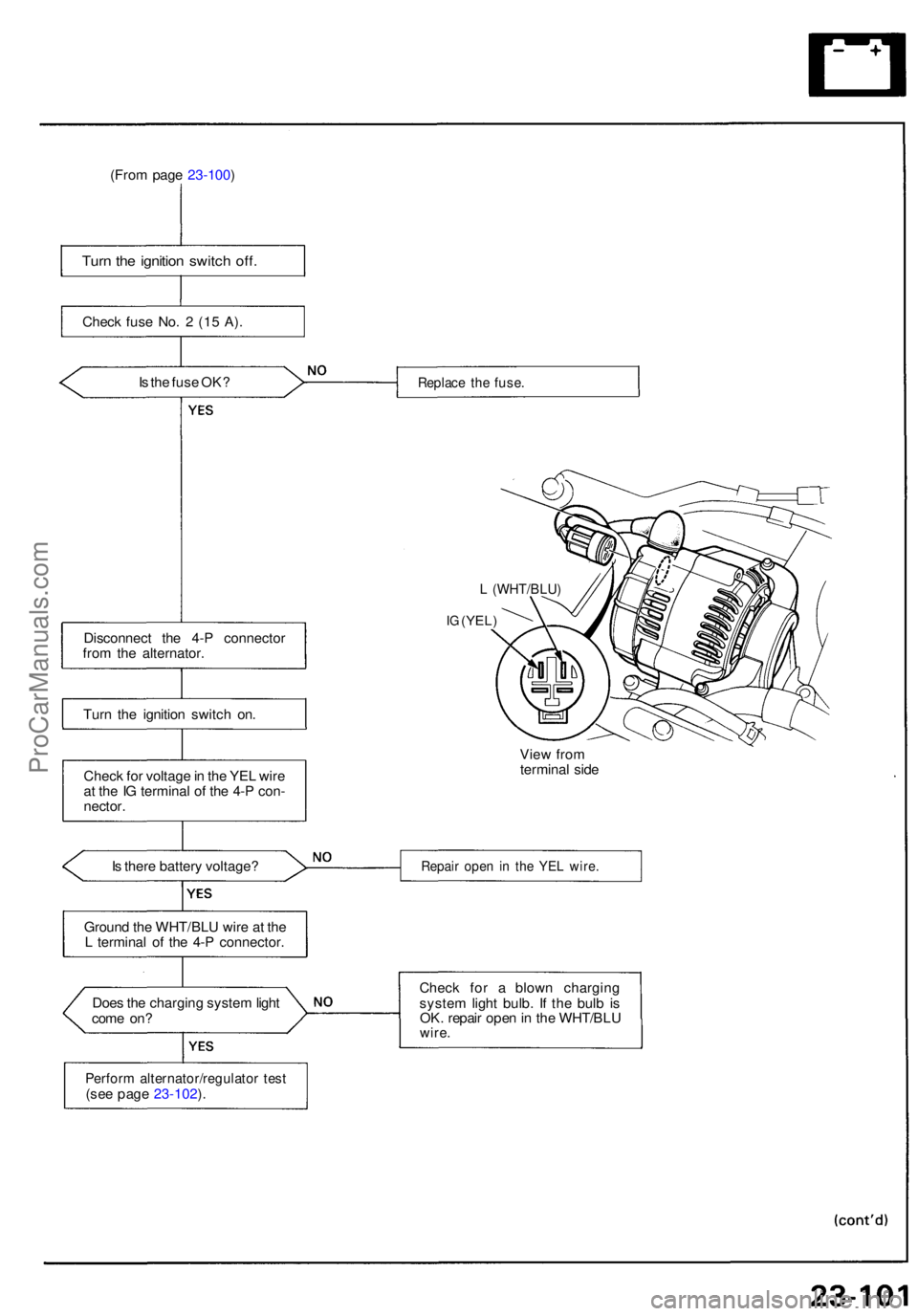
(From pag e 23-100 )
Turn th e ignitio n switc h off .
Chec k fus e No . 2 (1 5 A) .
I s th e fus e OK ?
Disconnec t th e 4- P connecto r
fro m th e alternator .
Tur n th e ignitio n switc h on .
Chec k fo r voltag e in th e YE L wir e
a t th e IG termina l o f th e 4- P con -
nector .
I s ther e batter y voltage ?
Groun d th e WHT/BL U wire at th e
L termina l o f th e 4- P connector .
Doe s th e chargin g syste m ligh t
com e on ?
Perfor m alternator/regulato r tes t(see pag e 23-102 ).
Replac e th e fuse .
L (WHT/BLU )
IG (YEL )
View fro m
termina l sid e
Repai r ope n i n th e YE L wire .
Check fo r a blow n chargin g
syste m ligh t bulb . I f th e bul b is
OK . repai r ope n in th e WHT/BL U
wire.
ProCarManuals.com
Page 789 of 1640
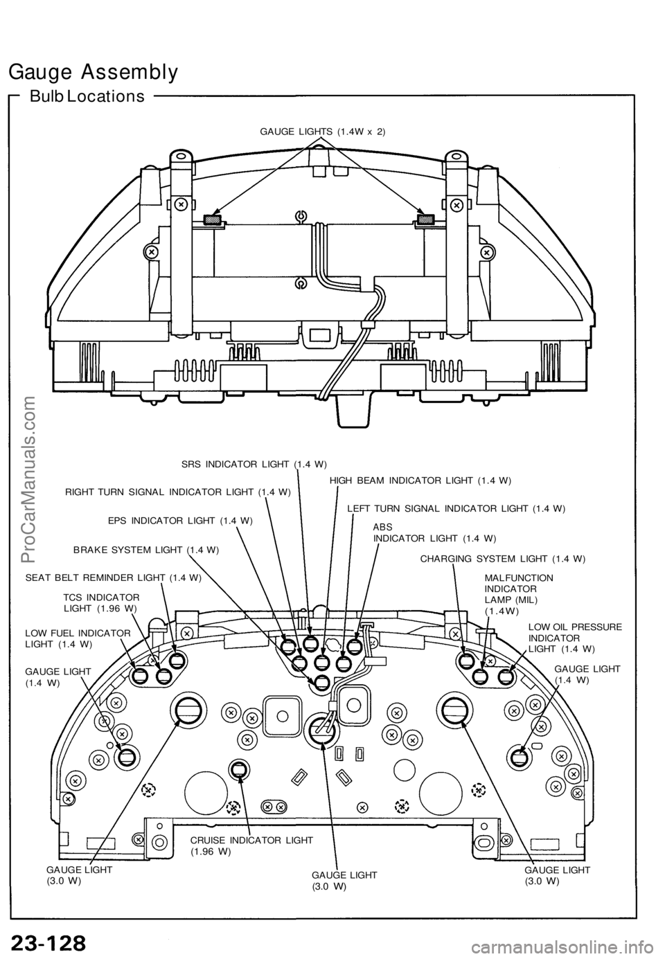
Gauge Assembly
Bulb Locations
GAUGE LIGHTS (1.4W x 2)
SRS INDICATOR LIGHT (1.4 W)
RIGHT TURN SIGNAL INDICATOR LIGHT (1.4 W)
EPS INDICATOR LIGHT (1.4 W)
BRAKE SYSTEM LIGHT (1.4 W)
SEAT BELT REMINDER LIGHT (1.4 W)
TCS INDICATOR
LIGHT (1.96 W)
LOW FUEL INDICATOR
LIGHT (1.4 W)
GAUGE LIGHT
(1.4
W)
HIGH BEAM INDICATOR LIGHT (1.4 W)
LEFT TURN SIGNAL INDICATOR LIGHT (1.4 W)
ABS
INDICATOR LIGHT (1.4 W)
CHARGING SYSTEM LIGHT (1.4 W)
MALFUNCTION
INDICATOR
LAMP (MIL)
(1.4W)
LOW OIL PRESSURE
INDICATOR
LIGHT (1.4 W)
GAUGE LIGHT
(1.4
W)
GAUGE LIGHT
(3.0
W)
GAUGE LIGHT
(3.0
W)
GAUGE LIGHT
(3.0
W)
CRUISE INDICATOR LIGHT
(1.96
W)ProCarManuals.com
Page 800 of 1640
Seat Bel t Reminde r Syste m
Seat Bel t Switc h Tes t
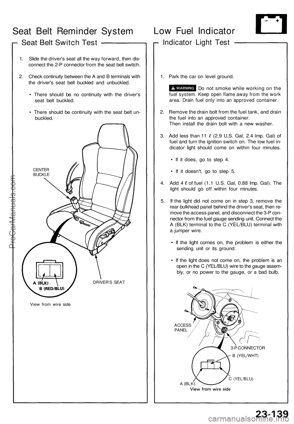
1. Slid e th e driver' s sea t al l th e wa y forward , the n dis -
connec t th e 2- P connecto r fro m th e sea t bel t switch .
2 . Chec k continuit y betwee n th e A an d B terminal s wit h
th e driver' s sea t bel t buckle d an d unbuckled .
• Ther e shoul d b e n o continuit y wit h th e driver' s
sea t bel t buckled .
• Ther e shoul d b e continuit y wit h th e sea t bel t un -
buckled .
CENTERBUCKL E
DRIVER' S SEA T
View fro m wir e sid e
Low Fue l Indicato r
Indicator Ligh t Tes t
1. Par k th e ca r o n leve l ground .
D o no t smok e whil e workin g o n th e
fue l system . Kee p ope n flam e awa y fro m th e wor k
area. Drai n fue l onl y int o a n approve d container .
2. Remov e th e drai n bol t fro m th e fue l tank , an d drai n
th e fue l int o a n approve d container .
The n instal l th e drai n bol t wit h a ne w washer .
3. Ad d les s tha n 1 1 (2. 9 U.S . Gal , 2. 4 Imp . Gal ) o f
fue l an d tur n th e ignitio n switc h on . Th e lo w fue l in -
dicato r ligh t shoul d com e o n withi n fou r minutes .
• I f i t does , g o t o ste p 4 .
• I f i t doesn't , g o t o ste p 5 .
4. Ad d 4 o f fue l (1. 1 U.S . Gal , 0.8 8 Imp . Gal) . Th e
ligh t shoul d g o of f withi n fou r minutes .
5 . I f th e ligh t di d no t com e o n i n ste p 3 , remov e th e
rea r bulkhea d pane l behin d th e driver' s seat , the n re -
mov e th e acces s panel , an d disconnec t th e 3- P con -
necto r fro m th e fue l gaug e sendin g unit . Connec t th e
A (BLK ) termina l t o th e C (YEL/BLU ) termina l wit h
a jumpe r wire .
• I f th e ligh t come s on , th e proble m is eithe r th e
sendin g uni t o r it s ground .
• I f th e ligh t doe s no t com e on , th e proble m is a n
ope n in th e C (YEL/BLU ) wir e to th e gaug e assem -
bly , o r n o powe r t o th e gauge , o r a ba d bulb .
ACCES SPANEL
3-P CONNECTO R
B (YEL/WHT )
A (BLK)C (YEL/BLU )
ProCarManuals.com
Page 805 of 1640
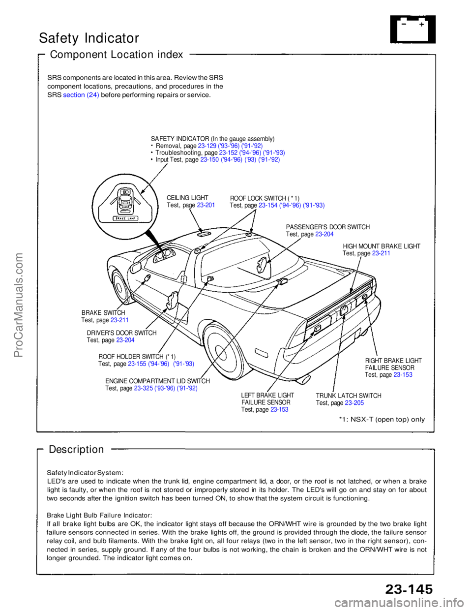
Safety Indicator
Component Location index
SRS components are located in this area. Review the SRS
component locations, precautions, and procedures in the
SRS section (24) before performing repairs or service.
SAFET
Y
INDICATOR (In the gauge assembly)
Removal, page 23-129 ('93-'96) ('91-'92)
Troubleshooting, page 23-152 ('94-'96) ('91-'93)
Input Test, page 23-150 ('94-'96) ('93) ('91-'92)
CEILING LIGHT
Test, page 23-201
ROOF LOCK SWITCH ( * 1)
Test, page 23-154 ('94-'96) ('91-'93)
PASSENGER'S DOOR SWITCH
Test, page 23-204
HIGH MOUNT BRAKE LIGHT
Test, page 23-211
BRAKE SWITCH
Test, page 23-211
DRIVER'S DOOR SWITCH
Test, page 23-204
ROOF HOLDER SWITCH (* 1)
Test, page 23-155 ('94-'96) ('91-'93)
ENGINE COMPARTMENT LID SWITCH
Test, page 23-325 ('93-'96) ('91-'92)
LEFT BRAKE LIGHT
FAILURE SENSOR
Test, page 23-153
TRUNK LATCH SWITCH
Test, page 23-205
RIGHT BRAKE LIGHT
FAILURE SENSOR
Test, page 23-153
*1: NSX-T (open top) only
Description
Safety Indicator System: LED's are used to indicate when the trunk lid, engine compartment lid, a door, or the roof is not latched, or when a brake
light is faulty, or when the roof is not stored or improperly stored in its holder. The LED's will go on and stay on for about
two seconds after the ignition switch has been turned ON, to show that the system circuit is functioning.
Brake Light Bulb Failure Indicator:
If all brake light bulbs are OK, the indicator light stays off because the ORN/WHT wire is grounded by the two brake light
failure sensors connected in series. With the brake lights off, the ground is provided through the diode, the failure sensor relay coil, and bulb filaments. With the brake light on, all four relays (two in the left sensor, two in the right sensor), con-
nected in series, supply ground. If any of the four bulbs is not working, the chain is broken and the ORN/WHT wire is not
longer grounded. The indicator light comes on.ProCarManuals.com
Page 816 of 1640
A/T Gear Position Switch
Replacement
SRS components are located in this area. Review the
SRS component locations, precautions, and procedures
in the SRS section (24) before performing repairs or ser-
vice.
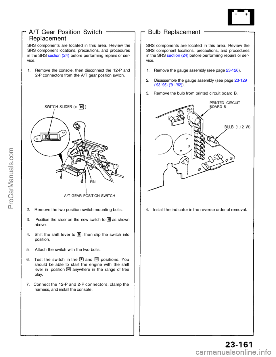
1. Remove the console, then disconnect the 12-P and 2-P connectors from the A/T gear position switch.
SWITCH SLIDER (In )
PIN
A/T GEAR POSITION SWITCH
2. Remove the two position switch mounting bolts. 3. Position the slider on the new switch to as shown
above.
4. Shift the shift lever to , then slip the switch into
position,
5. Attach the switch with the two bolts. 6. Test the switch in the and positions. You
should be able to start the engine with the shift lever in position anywhere in the range of free
play.
7. Connect the 12-P and 2-P connectors, clamp the harness, and install the console. Bulb Replacement
SRS components are located in this area. Review the
SRS component locations, precautions, and procedures in the SRS section (24) before performing repairs or ser-
vice.
1. Remove the gauge assembly (see page 23-126).
2. Disassemble the gauge assembly (see page 23-129
('93-'96) ('91-'92)).
3. Remove the bulb from printed circuit board B.
PRINTED CIRCUIT
BOARD B
BULB (1.12 W)
4. Install the indicator in the reverse order of removal.ProCarManuals.com
Page 833 of 1640
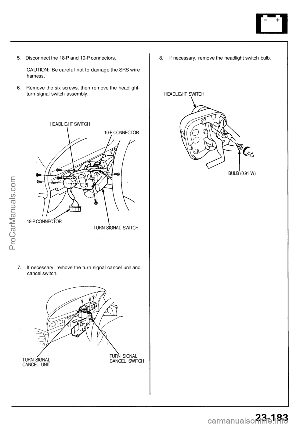
5. Disconnect the 18-P and 10-P connectors.
CAUTION: Be careful not to damage the SRS wire
harness.
6. Remove the six screws, then remove the headlight-
turn signal switch assembly.
HEADLIGHT SWITCH
10-P CONNECTOR
18-P CONNECTOR
TURN SIGNAL SWITCH
7. If necessary, remove the turn signal cancel unit and
cancel switch.
TURN SIGNAL
CANCEL UNIT
TURN SIGNAL
CANCEL SWITCH
8. If necessary, remove the headlight switch bulb.
HEADLIGHT SWITCH
BULB (0.91 W)ProCarManuals.com
Page 835 of 1640
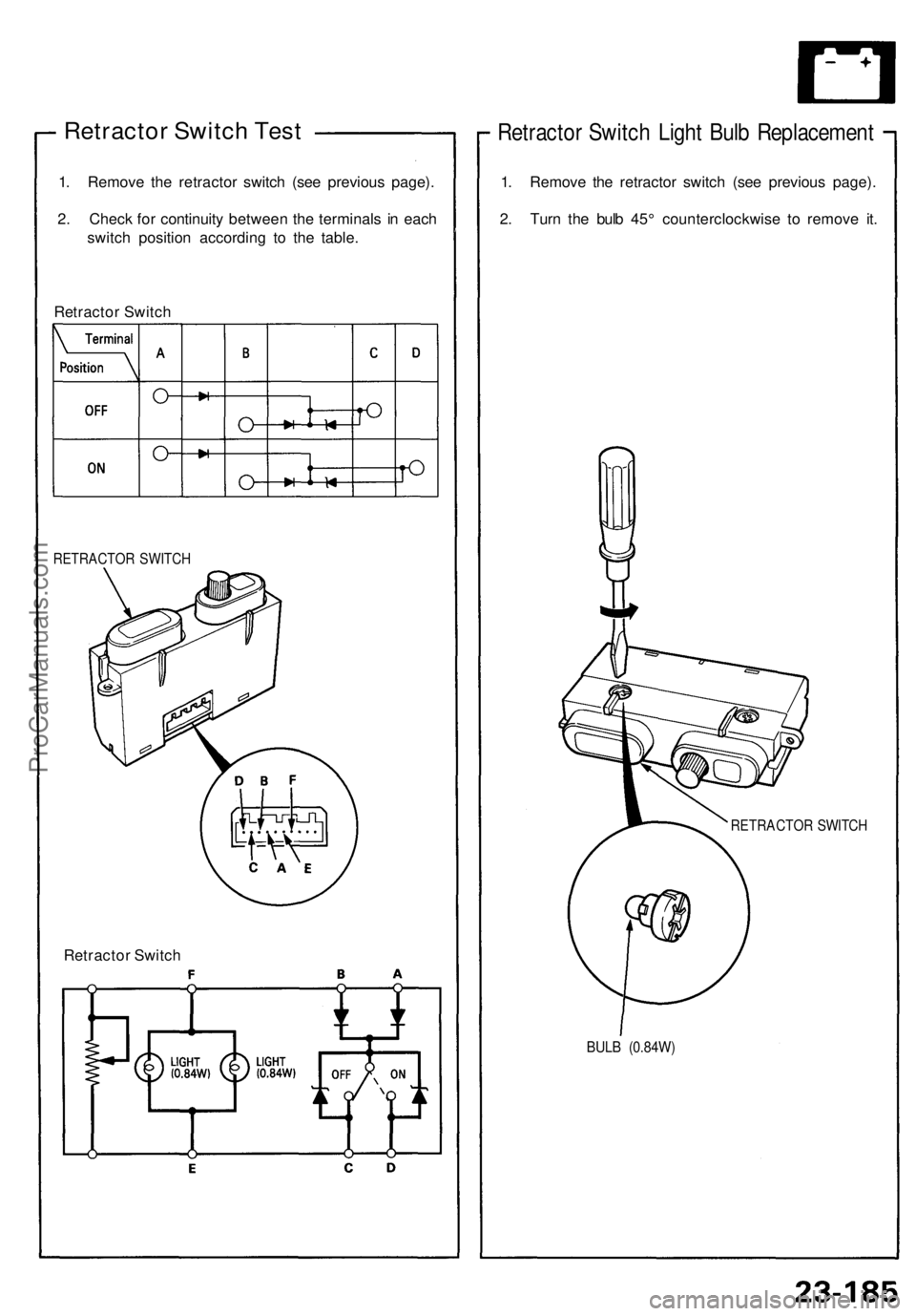
Retractor Switch Test
1. Remove the retractor switch (see previous page).
2. Check for continuity between the terminals in each
switch position according to the table.
Retractor Switch
RETRACTOR SWITCH
Retractor Switch
Retractor Switch Light Bulb Replacement
1. Remove the retractor switch (see previous page).
2. Turn the bulb 45° counterclockwise to remove it.
RETRACTOR SWITCH
BULB (0.84W)ProCarManuals.com