clutch ACURA NSX 1991 Service Repair Manual
[x] Cancel search | Manufacturer: ACURA, Model Year: 1991, Model line: NSX, Model: ACURA NSX 1991Pages: 1640, PDF Size: 60.48 MB
Page 80 of 1640
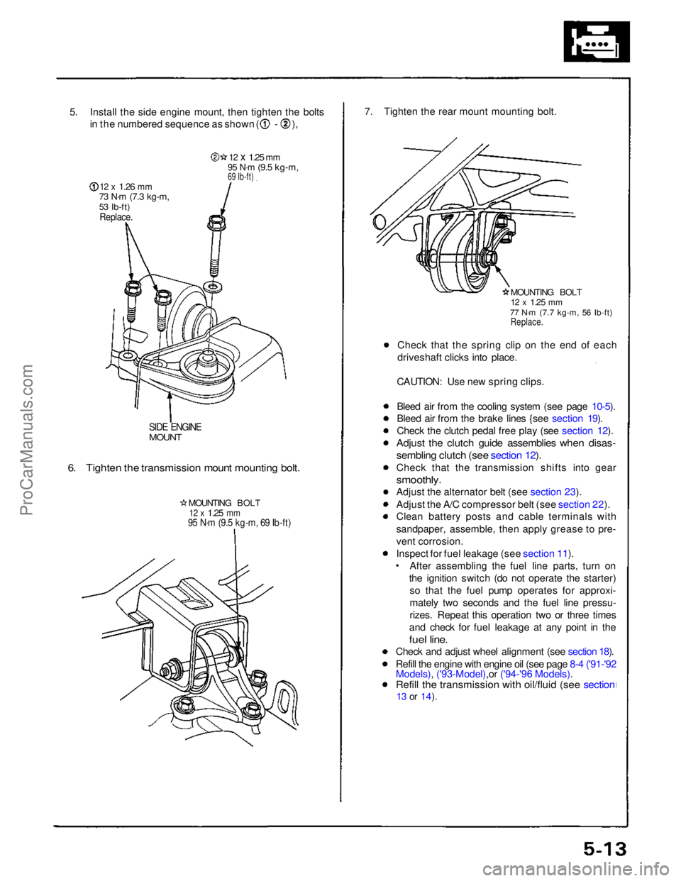
5. Install the side engine mount, then tighten the bolts
in the numbered sequence as shown ( - ),
12 x
1.26
mm
73 N·m
(7.3 kg-m,
53 Ib-ft)
Replace.
12 x
1.25
mm
95 N·m
(9.5 kg-m,
69 Ib-ft)
SIDE ENGINE
MOUNT
6. Tighten the transmission mount mounting bolt.
MOUNTING BOLT
12 x
1.25
mm
95 N·m (9.5 kg-m, 69 Ib-ft)
7. Tighten the rear mount mounting bolt.
MOUNTING BOLT
12 x
1.25
mm
77 N·m (7.7 kg-m, 56 Ib-ft)
Replace.
Check that the spring clip on the end of each
driveshaft clicks into place.
CAUTION: Use new spring clips.
Bleed air from the cooling system (see page 10-5).
Bleed air from the brake lines {see section 19).
Check the clutch pedal free play (see section 12).
Adjust the clutch guide assemblies when disas-
sembling clutch (see section 12).
Check that the transmission shifts into gear
smoothly.
Adjust the alternator belt (see section 23).
Adjust the A/C compressor belt (see section 22).
Clean battery posts and cable terminals with
sandpaper, assemble, then apply grease to pre-
vent corrosion.
Inspect for fuel leakage (see section 11). After assembling the fuel line parts, turn on
the ignition switch (do not operate the starter) so that the fuel pump operates for approxi-
mately two seconds and the fuel line pressu-
rizes. Repeat this operation two or three times
and check for fuel leakage at any point in the
fuel line.
Check and adjust wheel alignment (see section 18).
Refill the engine with engine oil (see page 8-4 ('91-'92
Models), ('93-Model),or ('94-'96 Models).
Refill the transmission with oil/fluid (see section
13 or
14).ProCarManuals.com
Page 237 of 1640
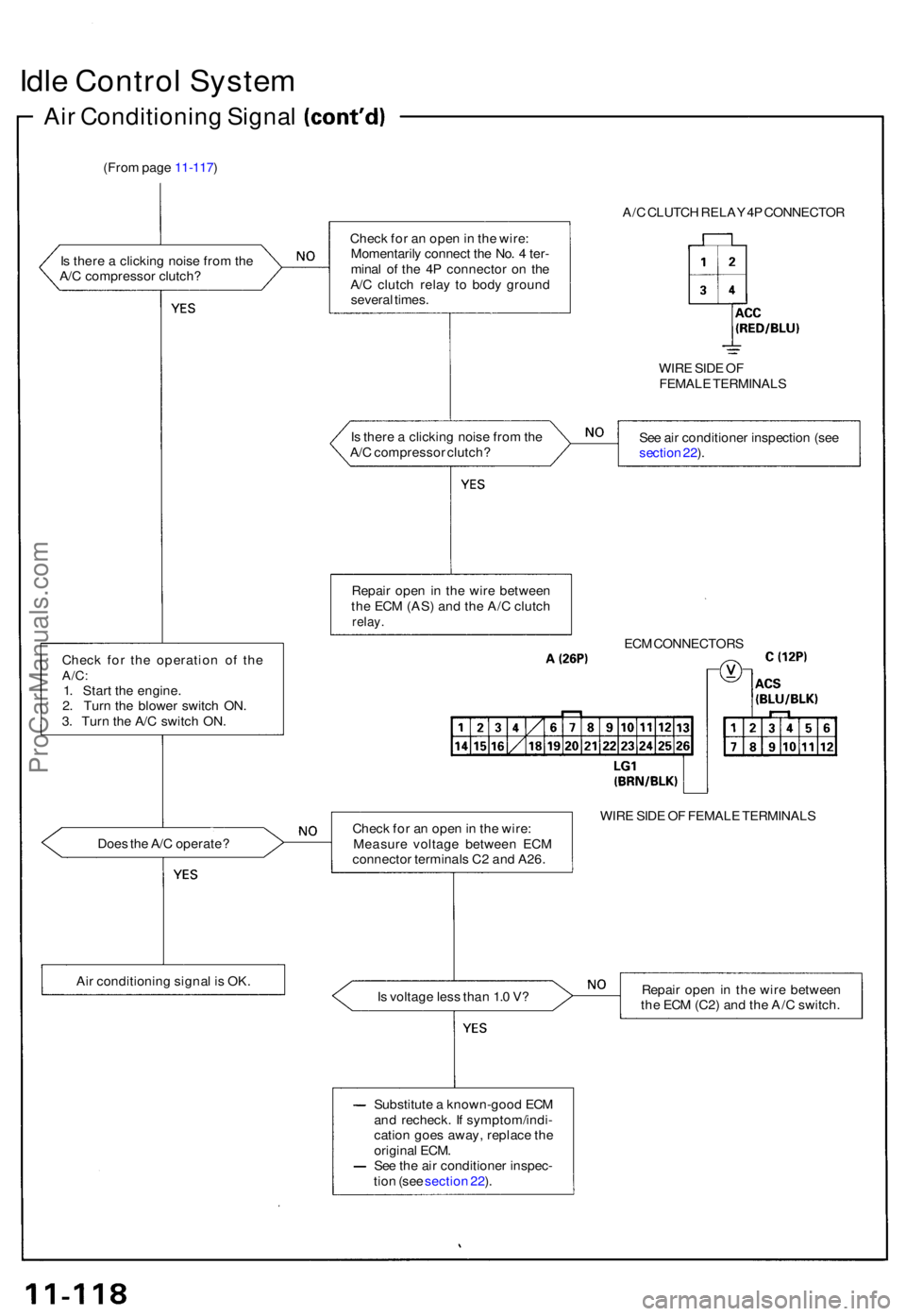
Idle Contro l Syste m
Air Conditionin g Signa l
(From pag e 11-117 )
I s ther e a clickin g nois e fro m th e
A/ C compresso r clutch ?
Chec k fo r th e operatio n o f th e
A/C :1. Star t th e engine .
2 . Tur n th e blowe r switc h ON .
3 . Tur n th e A/ C switc h ON .
Doe s th e A/ C operate ?
Ai r conditionin g signa l i s OK . A/
C CLUTC H RELA Y 4P CONNECTO R
Chec k fo r a n ope n in th e wire :
Momentaril y connec t th e No . 4 ter -
mina l o f th e 4 P connecto r o n th e
A/ C clutc h rela y t o bod y groun d
severa l times .
WIRE SID E O F
FEMAL E TERMINAL S
I s ther e a clickin g nois e fro m th e
A/ C compresso r clutch ? Se
e ai r conditione r inspectio n (se e
sectio n 22 ).
Repai r ope n in th e wir e betwee n
th e EC M (AS ) an d th e A/ C clutc h
relay.
ECM CONNECTOR S
Chec k fo r a n ope n in th e wire :
Measur e voltag e betwee n EC M
connecto r terminal s C 2 an d A26 . WIR
E SID E O F FEMAL E TERMINAL S
I s voltag e les s tha n 1. 0 V ? Repai
r ope n in th e wir e betwee n
th e EC M (C2 ) an d th e A/ C switch .
Substitut e a known-goo d EC M
an d recheck . I f symptom/indi -
catio n goe s away , replac e th e
origina l ECM .
Se e th e ai r conditione r inspec -
tio n (se e sectio n 22 ).
ProCarManuals.com
Page 243 of 1640
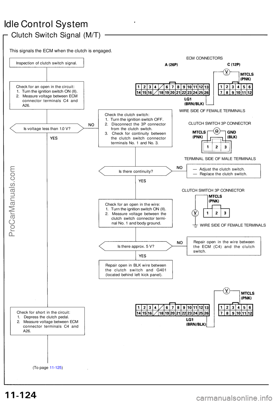
Idle Contro l Syste m
Clutch Switc h Signa l (M/T )
This signal s th e EC M whe n th e clutc h is engaged .
Inspection o f clutc h switc h signal .
Chec k fo r a n ope n in th e circuit :
1. Tur n th e ignitio n switc h O N (II) .2. Measur e voltag e betwee n EC M
connecto r terminal s C 4 an d
A26.
Is voltag e les s tha n 1. 0 V ?
Chec k fo r shor t i n th e circuit :
1 . Depres s th e clutc h pedal .
2 . Measur e voltag e betwee n EC M
connecto r terminal s C 4 an d
A26.
(To pag e 11-125 ) EC
M CONNECTOR S
Chec k th e clutc h switch :
1. Tur n th e ignitio n switc h OFF .2. Disconnec t th e 3 P connecto r
fro m th e clutc h switch .
3 . Chec k fo r continuit y betwee n
th e clutc h switc h connecto r
terminal s No . 1 an d No . 3 . WIR
E SID E O F FEMAL E TERMINAL S
CLUTC H SWITC H 3 P CONNECTO R
TERMINA L SID E O F MAL E TERMINAL S
I s ther e continuity ? —
Adjus t th e clutc h switch .
— Replac e th e clutc h switch .
CLUTC H SWITC H 3 P CONNECTO R
WIR E SID E O F FEMAL E TERMINAL S
I s ther e approx . 5 V ? Repai
r ope n i n th e wir e betwee n
th e EC M (C4 ) an d th e clutc h
switch .
Repai r ope n in BL K wir e betwee n
th e clutc h switc h an d G40 1
(locate d behin d lef t kic k panel) .
Chec
k fo r a n ope n in th e wire :
1. Tur n th e ignitio n switc h O N (II) .2. Measur e voltag e betwee n th e
clutc h switc h connecto r termi -
nal No . 1 an d bod y ground .
ProCarManuals.com
Page 246 of 1640
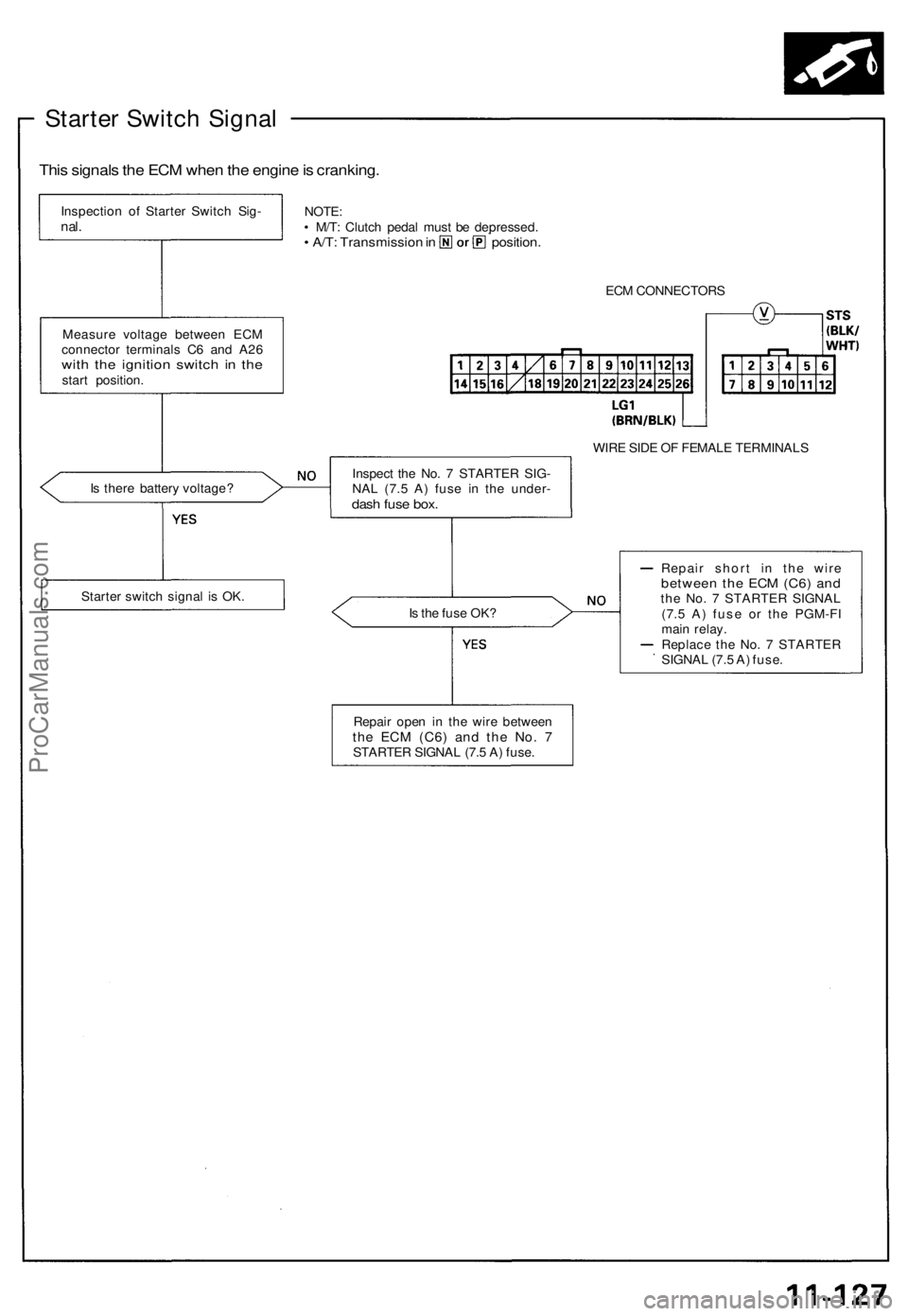
Starter Switch Signal
This signals the ECM when the engine is cranking.
Inspection of Starter Switch Sig-
nal.
NOTE:
• M/T: Clutch pedal must be depressed.
• A/T: Transmission in position.
ECM CONNECTORS
Measure voltage between ECM
connector terminals C6 and A26
with the ignition switch in the
start position.
WIRE SIDE OF FEMALE TERMINALS
Is there battery voltage?
Is the fuse OK?
Repair short in the wire
between the ECM (C6) and
the No. 7 STARTER SIGNAL
(7.5 A) fuse or the PGM-FI
main relay.
Replace the No. 7 STARTER
SIGNAL (7.5 A) fuse.
Starter switch signal is OK.
Repair open in the wire between
the ECM
(C6)
and the No. 7
STARTER SIGNAL (7.5 A) fuse.
Inspect the No. 7 STARTER SIG-
NAL (7.5 A) fuse in the under-
dash fuse box.ProCarManuals.com
Page 282 of 1640
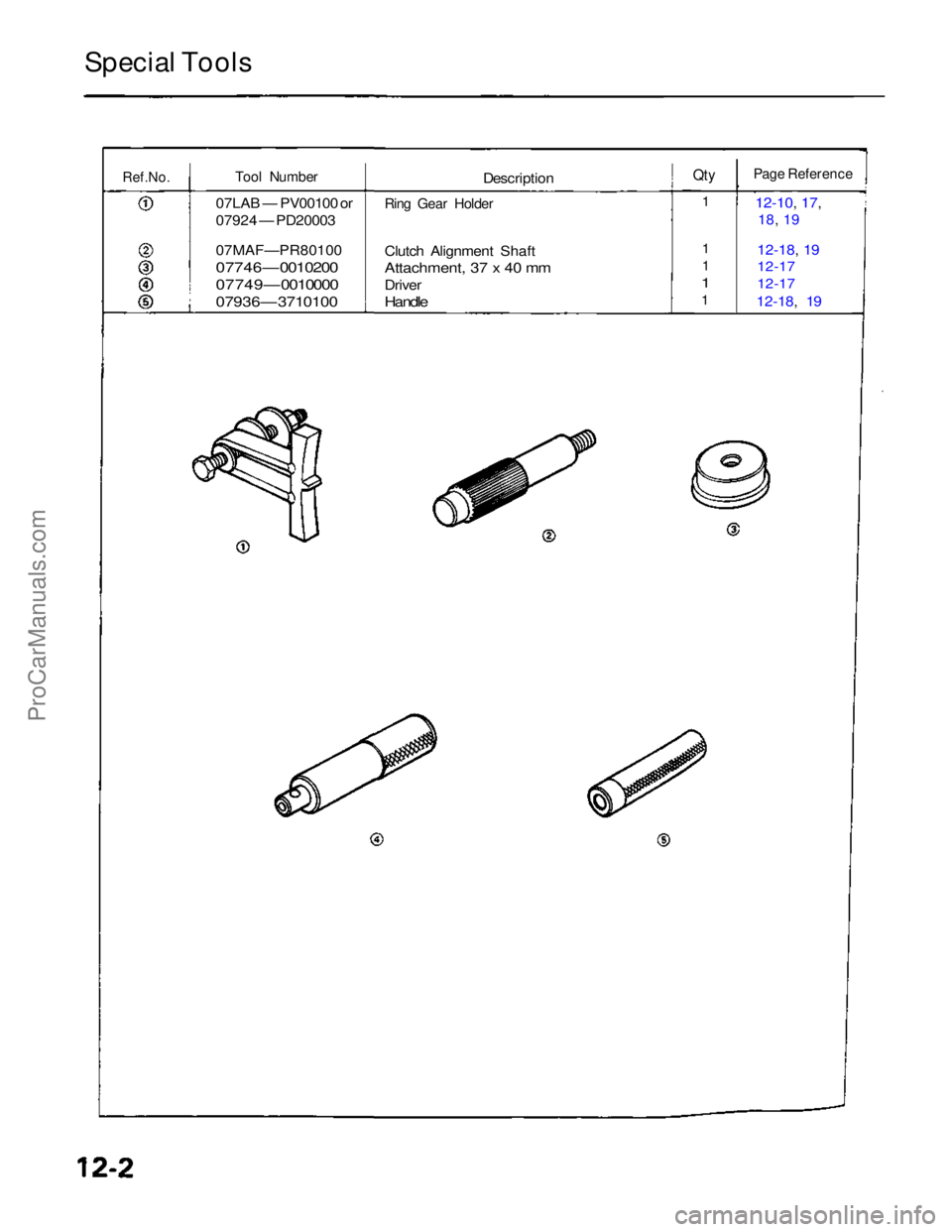
Special Tools
Ref.No.
Tool Number
07LAB — PV00100 or
07924 — PD20003
07MAF—PR80100
07746 — 0010200
07749 — 0010000
07936 — 3710100
Description
Ring Gear Holder
Clutch Alignment Shaft
Attachment, 37 x 40 mm
Driver
Handle
Qty
Page Reference
12-10, 17,
18, 19
12-18, 19
12-17
12-17
12-18, 19
1
1
1
1
1ProCarManuals.com
Page 283 of 1640
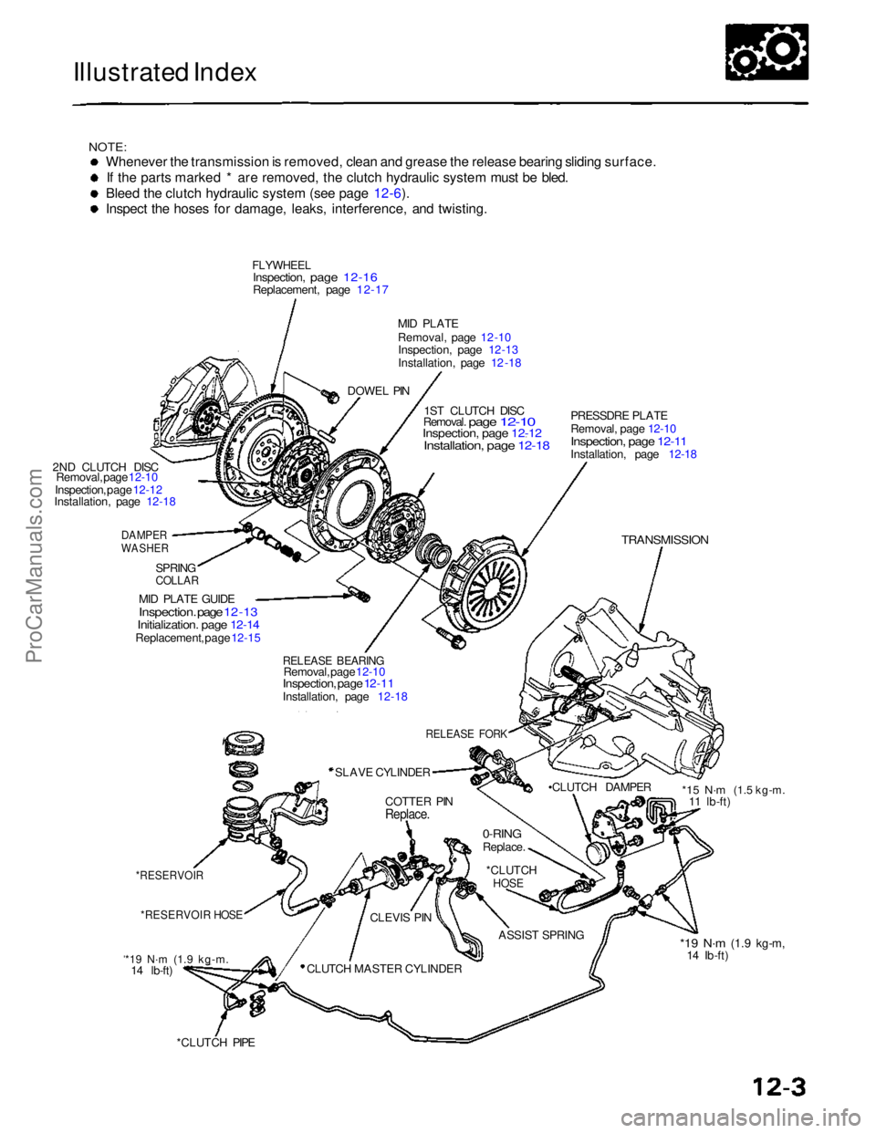
Illustrated Index
NOTE:
Whenever the transmission is removed, clean and grease the release bearing sliding surface.
If the parts marked * are removed, the clutch hydraulic system must be bled.
Bleed the clutch hydraulic system (see page 12-6).
Inspect the hoses for damage, leaks, interference, and twisting.
FLYWHEEL
Inspection, page 12-16
Replacement,
page 12-17
MID PLATE
Removal, page 12 -10
Inspection, page 12 -13
Installation, page 12 -18
2ND CLUTCH DISC Removal, page 12-10
Inspection, page 12-12
Installation, page 12-18
DAMPER
WASHER
PRESSDRE PLATE
Removal, page 12-10 Inspection, page 12-11
Installation, page 12-18
TRANSMISSION
1ST CLUTCH DISC
Removal. page 12-10 Inspection, page 12-12
Installation, page 12-18
SPRING
COLLAR
RELEASE BEARING
Removal, page 12-10
Inspection, page 12-11
Installation, page 12-18
RELEASE FORK
SLAVE CYLINDER •CLUTCH DAMPER
COTTER PIN
Replace.
0-RING
Replace.
*RESERVOIR HOSE
ASSIST SPRING
CLUTCH MASTER CYLINDER
MID PLATE GUIDE
Inspection. page 12 -13
Initialization. page 12-14
Replacement, page 12-15
*15 N·m
(1.5 kg-m.11 lb-ft)
*RESERVOIR
*19 N·m (1.9 kg-m.
14 lb-ft)
*CLUTCH PIPE
*19 N·m
(1.9 kg-m,
14 Ib-ft)
*CLUTCH
HOSE
CLEVIS PIN
DOWEL PINProCarManuals.com
Page 284 of 1640
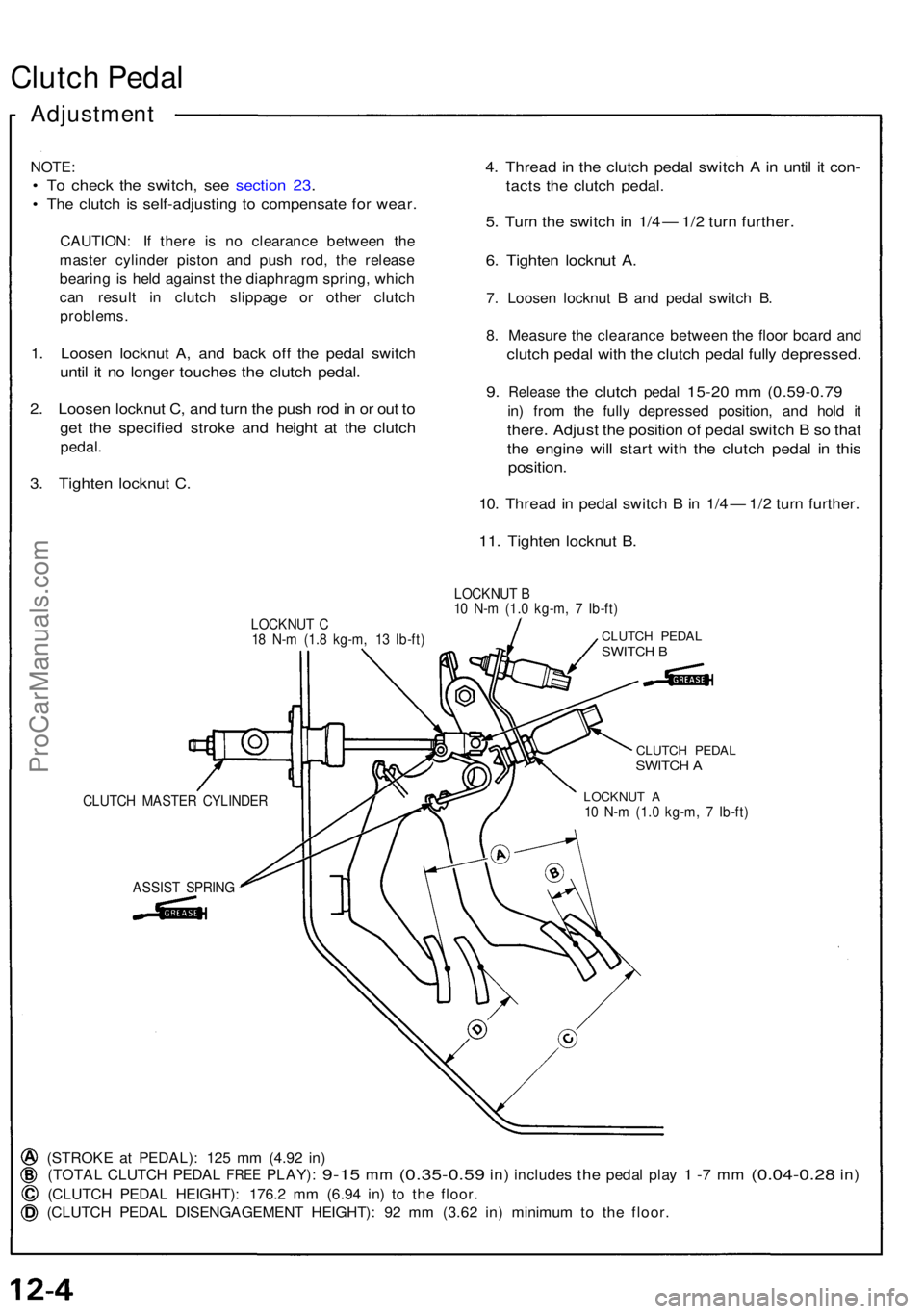
Clutch Peda l
Adjustmen t
NOTE:
• T o chec k th e switch , se e sectio n 23 .
• Th e clutc h i s self-adjustin g t o compensat e fo r wear .
CAUTION : I f ther e i s n o clearanc e betwee n th e
maste r cylinde r pisto n an d pus h rod , th e releas e
bearin g is hel d agains t th e diaphrag m spring , whic h
ca n resul t i n clutc h slippag e o r othe r clutc h
problems .
1. Loose n locknu t A , an d bac k of f th e peda l switc h
until i t n o longe r touche s th e clutc h pedal .
2. Loose n locknu t C , an d tur n th e pus h ro d in o r ou t t o
ge t th e specifie d strok e an d heigh t a t th e clutc h
pedal.
3. Tighte n locknu t C .
4. Threa d in th e clutc h peda l switc h A in unti l i t con -
tacts th e clutc h pedal .
5. Tur n th e switc h in 1/ 4 — 1/2 tur n further .
6. Tighte n locknu t A .
7. Loose n locknu t B an d peda l switc h B .
8 . Measur e th e clearanc e betwee n th e floo r boar d an d
clutc h peda l wit h th e clutc h peda l full y depressed .
9. Releas e the clutc h peda l 15-20 m m (0.59-0.7 9
in) fro m th e full y depresse d position , an d hol d i t
there . Adjus t th e positio n o f peda l switc h B so tha t
the engin e wil l star t wit h th e clutc h peda l i n thi s
position .
10. Threa d in peda l switc h B in 1/ 4 — 1/2 tur n further .
11. Tighte n locknu t B .
LOCKNU T C
1 8 N- m (1. 8 kg-m , 1 3 Ib-ft ) LOCKNU
T B
1 0 N- m (1. 0 kg-m , 7 Ib-ft )CLUTC H PEDA LSWITCH B
ASSIS T SPRIN G
CLUTCH PEDA LSWITCH A
LOCKNU T A10 N- m (1. 0 kg-m , 7 Ib-ft )
(STROK E a t PEDAL) : 12 5 m m (4.9 2 in )
(TOTA L CLUTC H PEDA L FREE PLAY) : 9-15 mm (0.35-0.5 9 in) include s the peda l pla y 1 -7 m m (0.04-0.2 8 in)
(CLUTC H PEDA L HEIGHT) : 176. 2 m m (6.9 4 in ) t o th e floor .
(CLUTC H PEDA L DISENGAGEMEN T HEIGHT) : 9 2 m m (3.6 2 in ) minimu m to th e floor .
CLUTC H MASTE R CYLINDE R
ProCarManuals.com
Page 285 of 1640
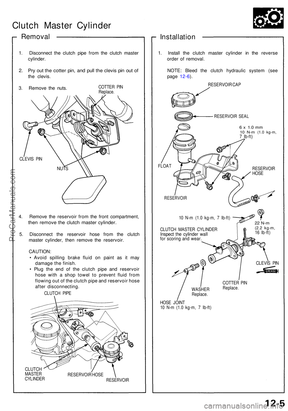
Clutch Maste r Cylinde r
Removal
1. Disconnec t th e clutc h pip e fro m th e clutc h maste r
cylinder .
2. Pr y ou t th e cotte r pin , an d pul l th e clevi s pi n ou t o f
the clevis .
3 . Remov e th e nuts .
COTTE R PI N
Replace .
CLEVI S PI N
4. Remov e th e reservoi r fro m th e fron t compartment ,
then remov e th e clutc h maste r cylinder .
5. Disconnec t th e reservoi r hos e fro m th e clutc h
maste r cylinder , the n remov e th e reservoir .
CAUTION :
• Avoi d spillin g brak e flui d o n pain t a s i t ma y
damag e th e finish .
• Plu g th e en d o f th e clutc h pip e an d reservoi r
hos e wit h a sho p towe l t o preven t flui d fro m
flowin g ou t o f th e clutc h pip e an d reservoi r hos e
afte r disconnecting .
CLUTCH PIP E
CLUTC HMASTE R
CYLINDE R RESERVOI
R HOS E
RESERVOI R
Installation
1. Instal l th e clutc h maste r cylinde r i n th e revers e
orde r of removal .
NOTE : Blee d th e clutc h hydrauli c syste m (se e
pag e 12-6 ).
RESERVOI R CA P
RESERVOI R SEA L
6 x 1. 0 m m10 N- m (1. 0 kg-m ,7 Ib-ft )
FLOA T
RESERVOI R
10 N- m (1. 0 kg-m , 7 Ib-ft )
CLUTC H MASTE R CYLINDE R
Inspect th e cylinde r wal lfor scorin g an d wear .
RESERVOI RHOSE
22 N- m(2.2 kg-m ,16 Ib-ft )
COTTE R PI N
Replace .
HOSE JOIN T
1 0 N- m (1. 0 kg-m , 7 Ib-ft )
NUTS
CLEVI S PI N
WASHE RReplace .
ProCarManuals.com
Page 286 of 1640

Slave Cylinde r
Remova l
1. Disconnec t th e clutc h hos e fro m th e slav e cylinder .
CAUTION :
• Avoi d spillin g brak e flui d o n th e painte d sur -
faces , a s i t ma y damag e th e finish .
• Plu g th e en d o f th e clutc h hos e wit h a sho p
towe l t o preven t brak e flui d fro m comin g out .
2. Remov e th e slav e cylinde r fro m th e clutc h housing .
SLAVE
CYLINDE R
CLUTCHHOSE
O-RIN G
Replace .
BOO T
Remov e an d chec k fo r sign s o f leakin gand deterioration .
Installation
Super Hig h Tem p Ure a Greas e (P/ N
08798-9002) .
Brake Assembl y Lub e o r equivalen t rubbe r
grease .
1. Instal l th e slav e cylinde r o n th e clutc h housing .
SLAVE CYLINDE R
8 x 1.2 5 mm22 N- m (2. 2 kg-m ,16 Ib-ft )
10 N- m (1. 0 kg-m ,7 Ib-ft )
(P/N 08798-9002 )(Brake Assembl y
Lube )
2. Blee d th e clutc h hydrauli c system :
• Attac h a hos e t o th e bleede r screw , the n suspen d
th e hos e i n a containe r o f brak e fluid .
• Mak e sur e ther e i s a n adequat e suppl y of flui d a t
the maste r cylinder , the n slowl y pum p th e
clutc h peda l unti l n o mor e bubble s appea r a t th e
bleede r hose .
• Refil l th e maste r cylinde r flui d whe n done .
• Us e onl y DO T 3 or 4 brak e fluid .
6 x 1. 0 m m10 N- m (1. 0 kg-m ,7 Ib-ft )
ProCarManuals.com
Page 287 of 1640
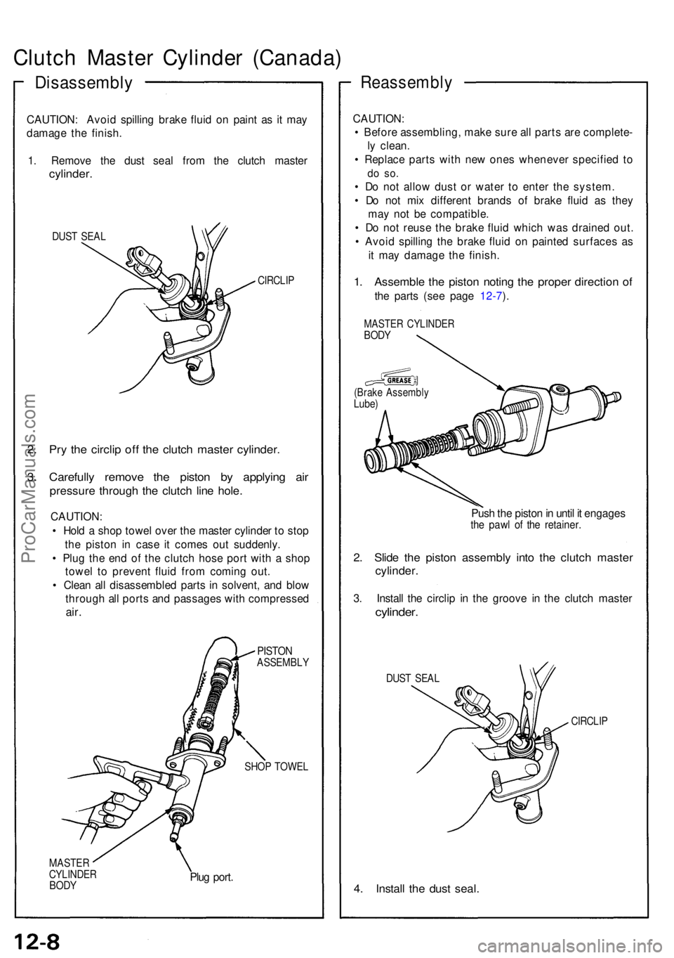
Clutch Maste r Cylinde r (Canada )
Disassembl y
CAUTION: Avoi d spillin g brak e flui d o n pain t a s it ma y
damag e th e finish .
1 . Remov e th e dus t sea l fro m th e clutc h maste r
cylinder.
DUST SEA L
CIRCLI P
2. Pr y th e circli p of f th e clutc h maste r cylinder .
3. Carefull y remov e th e pisto n b y applyin g ai r
pressur e throug h th e clutc h lin e hole .
CAUTION :
• Hol d a sho p towe l ove r th e maste r cylinde r t o sto p
th e pisto n i n cas e i t come s ou t suddenly .
• Plu g th e en d o f th e clutc h hos e por t wit h a sho p
towe l t o preven t flui d fro m comin g out .
• Clea n al l disassemble d part s in solvent , an d blo w
throug h al l port s an d passage s wit h compresse d
air.
PISTO NASSEMBL Y
SHOP TOWE L
MASTE RCYLINDE RBODYPlug port .
Reassembl y
CAUTION:
• Befor e assembling , mak e sur e al l part s ar e complete -
l y clean .
• Replac e part s wit h ne w one s wheneve r specifie d t o
do so .
• D o no t allo w dus t o r wate r t o ente r th e system .
• D o no t mi x differen t brand s o f brak e flui d a s the y
ma y no t b e compatible .
• D o no t reus e th e brak e flui d whic h wa s draine d out .
• Avoi d spillin g th e brak e flui d o n painte d surface s a s
i t ma y damag e th e finish .
1. Assembl e th e pisto n notin g th e prope r directio n o f
the part s (se e pag e 12-7 ).
MASTE R CYLINDE RBODY
(Brak e Assembl yLube)
Push th e pisto n in unti l i t engage sthe paw l o f th e retainer .
2. Slid e th e pisto n assembl y int o th e clutc h maste r
cylinder .
3. Instal l th e circli p i n th e groov e i n th e clutc h maste r
cylinder.
DUST SEA L
CIRCLI P
4. Instal l th e dus t seal .
ProCarManuals.com