fuel pump ACURA NSX 1991 Service Repair Manual
[x] Cancel search | Manufacturer: ACURA, Model Year: 1991, Model line: NSX, Model: ACURA NSX 1991Pages: 1640, PDF Size: 60.48 MB
Page 80 of 1640
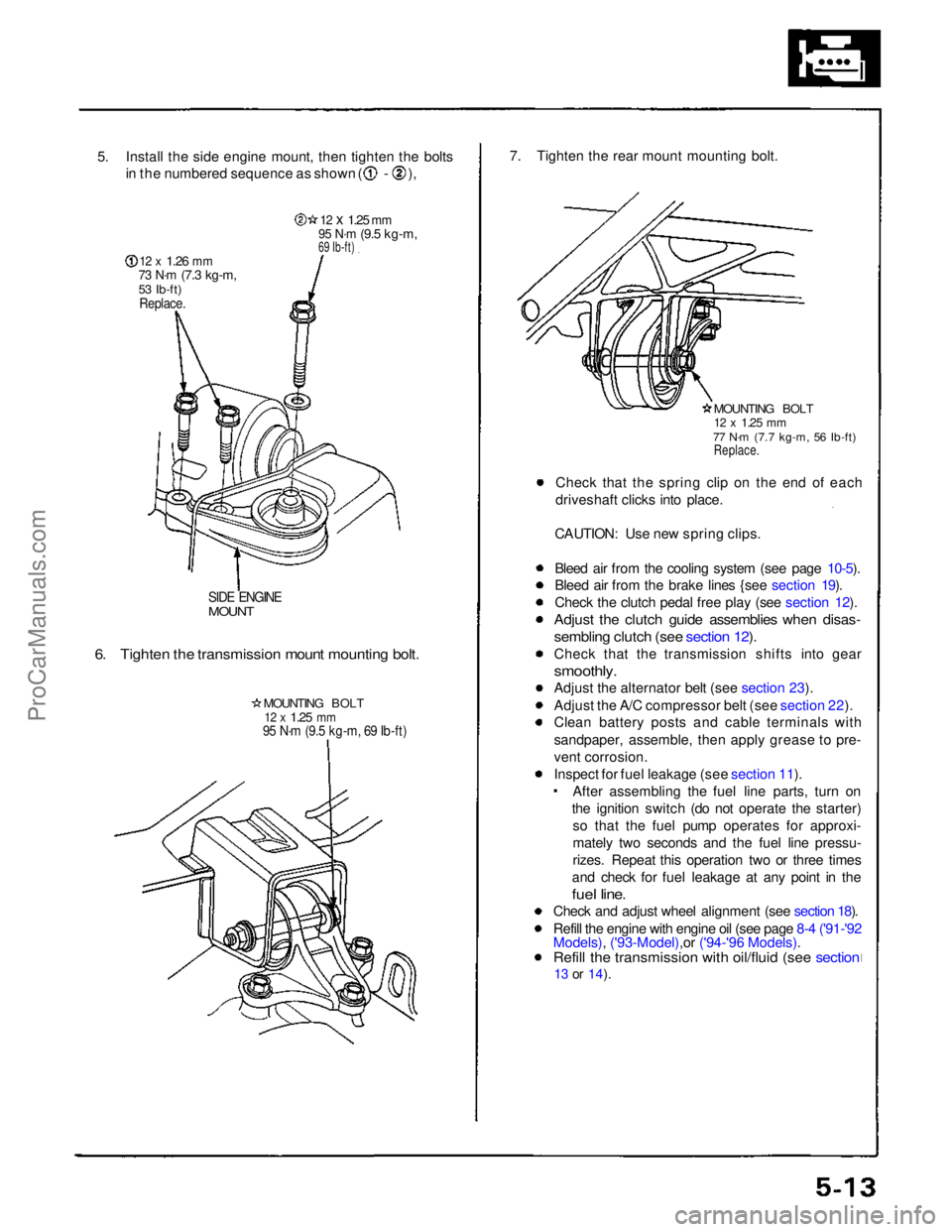
5. Install the side engine mount, then tighten the bolts
in the numbered sequence as shown ( - ),
12 x
1.26
mm
73 N·m
(7.3 kg-m,
53 Ib-ft)
Replace.
12 x
1.25
mm
95 N·m
(9.5 kg-m,
69 Ib-ft)
SIDE ENGINE
MOUNT
6. Tighten the transmission mount mounting bolt.
MOUNTING BOLT
12 x
1.25
mm
95 N·m (9.5 kg-m, 69 Ib-ft)
7. Tighten the rear mount mounting bolt.
MOUNTING BOLT
12 x
1.25
mm
77 N·m (7.7 kg-m, 56 Ib-ft)
Replace.
Check that the spring clip on the end of each
driveshaft clicks into place.
CAUTION: Use new spring clips.
Bleed air from the cooling system (see page 10-5).
Bleed air from the brake lines {see section 19).
Check the clutch pedal free play (see section 12).
Adjust the clutch guide assemblies when disas-
sembling clutch (see section 12).
Check that the transmission shifts into gear
smoothly.
Adjust the alternator belt (see section 23).
Adjust the A/C compressor belt (see section 22).
Clean battery posts and cable terminals with
sandpaper, assemble, then apply grease to pre-
vent corrosion.
Inspect for fuel leakage (see section 11). After assembling the fuel line parts, turn on
the ignition switch (do not operate the starter) so that the fuel pump operates for approxi-
mately two seconds and the fuel line pressu-
rizes. Repeat this operation two or three times
and check for fuel leakage at any point in the
fuel line.
Check and adjust wheel alignment (see section 18).
Refill the engine with engine oil (see page 8-4 ('91-'92
Models), ('93-Model),or ('94-'96 Models).
Refill the transmission with oil/fluid (see section
13 or
14).ProCarManuals.com
Page 228 of 1640
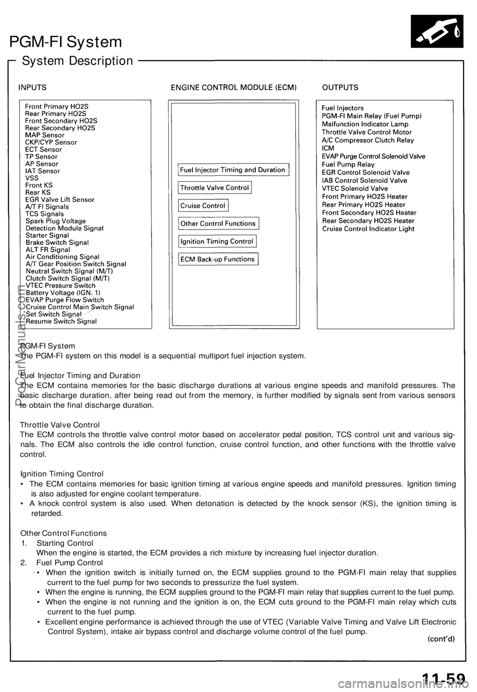
PGM-FI System
System Description
PGM-FI System
The PGM-FI system on this model is a sequential multiport fuel injection system.
Fuel Injector Timing and Duration
The ECM contains memories for the basic discharge durations at various engine speeds and manifold pressures. The
basic discharge duration, after being read out from the memory, is further modified by signals sent from various sensors
to obtain the final discharge duration.
Throttle Valve Control
The ECM controls the throttle valve control motor based on accelerator pedal position, TCS control unit and various sig-
nals. The ECM also controls the idle control function, cruise control function, and other functions with the throttle valve
control.
Ignition Timing Control
• The ECM contains memories for basic ignition timing at various engine speeds and manifold pressures. Ignition timing
is also adjusted for engine coolant temperature.
• A knock control system is also used. When detonation is detected by the knock sensor (KS), the ignition timing is
retarded.
Other Control Functions
1. Starting Control
When the engine is started, the ECM provides a rich mixture by increasing fuel injector duration.
2. Fuel Pump Control
• When the ignition switch is initially turned on, the ECM supplies ground to the PGM-FI main relay that supplies
current to the fuel pump for two seconds to pressurize the fuel system.
• When the engine is running, the ECM supplies ground to the PGM-FI main relay that supplies current to the fuel pump.
• When the engine is not running and the ignition is on, the ECM cuts ground to the PGM-FI main relay which cuts
current to the fuel pump.
• Excellent engine performance is achieved through the use of VTEC (Variable Valve Timing and Valve Lift Electronic
Control System), intake air bypass control and discharge volume control of the fuel pump.ProCarManuals.com
Page 254 of 1640
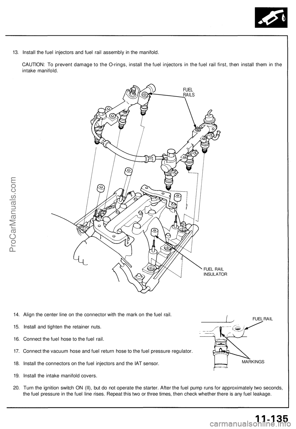
13. Install the fuel injectors and fuel rail assembly in the manifold.
CAUTION: To prevent damage to the O-rings, install the fuel injectors in the fuel rail first, then install them in the
intake manifold.
FUEL
RAILS
FUEL RAIL
INSULATOR
FUEL RAIL
14. Align the center line on the connector with the mark on the fuel rail.
15. Install and tighten the retainer nuts.
16. Connect the fuel hose to the fuel rail.
17. Connect the vacuum hose and fuel return hose to the fuel pressure regulator.
18. Install the connectors on the fuel injectors and the IAT sensor.
19. Install the intake manifold covers.
20. Turn the ignition switch ON (II), but do not operate the starter. After the fuel pump runs for approximately two seconds,
the fuel pressure in the fuel line rises. Repeat this two or three times, then check whether there is any fuel leakage.
MARKINGSProCarManuals.com
Page 259 of 1640
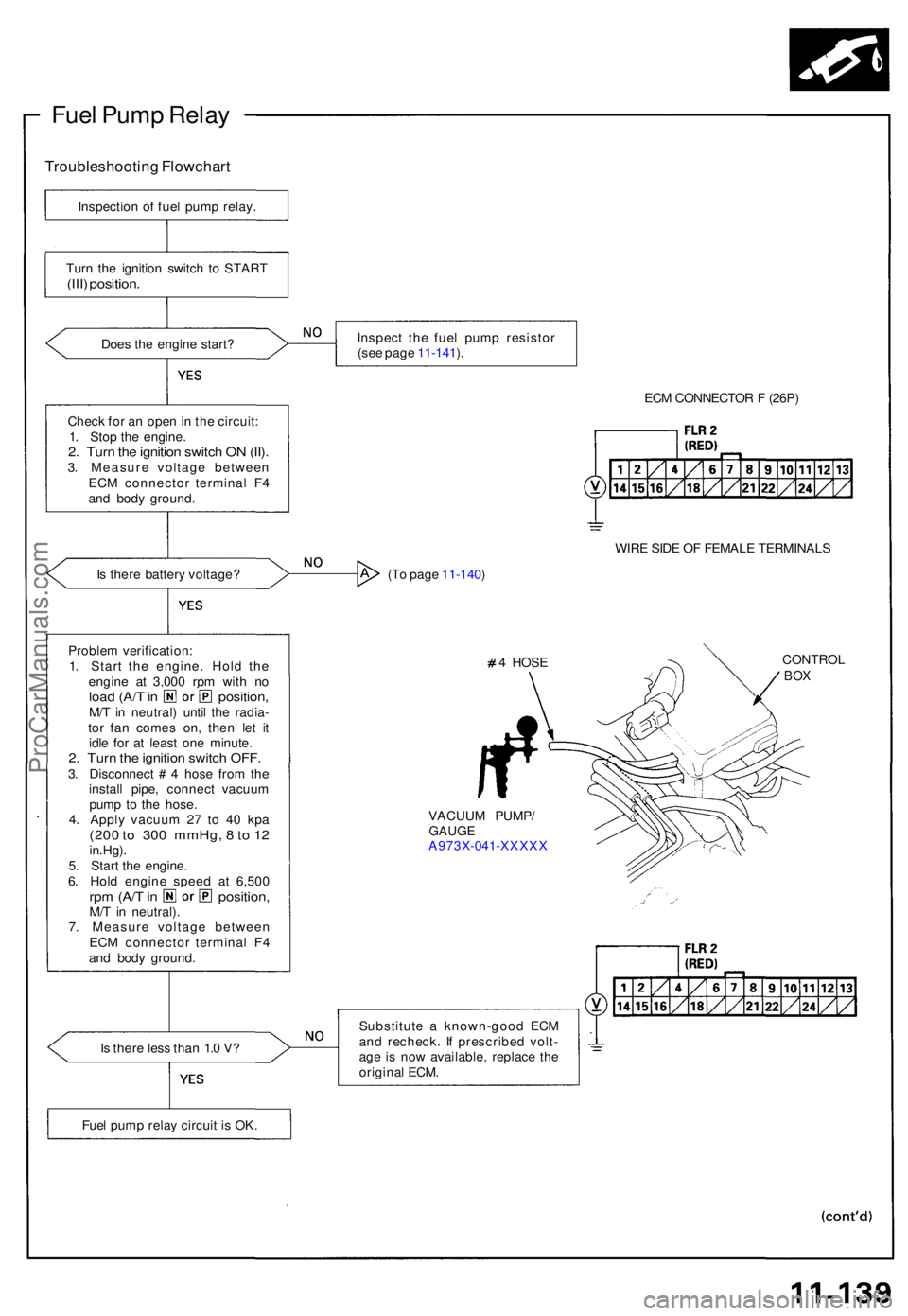
Fuel Pum p Rela y
Troubleshootin g Flowchar t
Inspection o f fue l pum p relay .
Tur n th e ignitio n switc h t o STAR T
(III) position .
Does th e engin e start ?
Chec k fo r a n ope n in th e circuit :
1 . Sto p th e engine .
2. Tur n th e ignitio n switc h O N (II) .3. Measur e voltag e betwee n
EC M connecto r termina l F 4
an d bod y ground .
I s ther e batter y voltage ?
Proble m verification :
1 . Star t th e engine . Hol d th e
engin e a t 3,00 0 rp m wit h n o
loa d (A/ T in position ,M/T in neutral ) unti l th e radia -
to r fa n come s on , the n le t i t
idl e fo r a t leas t on e minute .
2. Tur n th e ignitio n switc h OFF .3. Disconnec t # 4 hos e fro m th e
instal l pipe , connec t vacuu m
pum p t o th e hose .
4 . Appl y vacuu m 2 7 t o 4 0 kp a
(200 t o 300 mmHg , 8 to 1 2in.Hg) .
5 . Star t th e engine .
6 . Hol d engin e spee d a t 6,50 0
rpm (A/ T in position ,M/T in neutral) .
7 . Measur e voltag e betwee n
EC M connecto r termina l F 4
an d bod y ground .
I s ther e les s tha n 1. 0 V ? Inspec
t th e fue l pum p resisto r
(se e pag e 11-141 ).
ECM CONNECTO R F (26P )
WIR E SID E O F FEMAL E TERMINAL S
(T o pag e 11-140 )
4 HOS E
CONTRO LBOX
VACUU M PUMP /GAUGEA973X-04 1-XXXX X
Substitut e a known-goo d EC M
an d recheck . I f prescribe d volt -
ag e i s no w available , replac e th e
origina l ECM .
Fue l pum p rela y circui t i s OK .
ProCarManuals.com
Page 261 of 1640
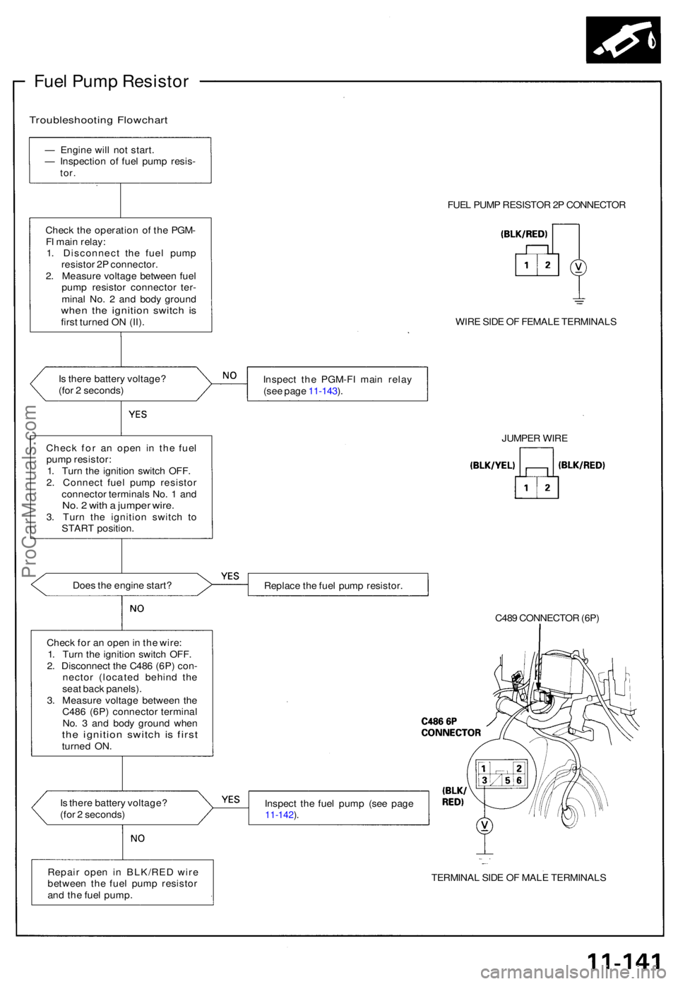
Fuel Pum p Resisto r
Troubleshootin g Flowchar t
— Engin e wil l no t start .
— Inspectio n o f fue l pum p resis -
tor.
Chec k th e operatio n o f th e PGM -
F I mai n relay :
1 . Disconnec t th e fue l pum p
resisto r 2 P connector .
2 . Measur e voltag e betwee n fue l
pum p resisto r connecto r ter -
mina l No . 2 an d bod y groun d
when th e ignitio n switc h i sfirs t turne d O N (II) .
I s ther e batter y voltage ?
(fo r 2 seconds )
Doe s th e engin e start ?
Chec k fo r a n ope n in th e wire :
1 . Tur n th e ignitio n switc h OFF .
2 . Disconnec t th e C48 6 (6P ) con -
necto r (locate d behin d th e
sea t bac k panels) .
3 . Measur e voltag e betwee n th e
C48 6 (6P ) connecto r termina l
No . 3 an d bod y groun d whe n
the ignitio n switc h i s firs tturne d ON .
I s ther e batter y voltage ?
(fo r 2 seconds ) FUE
L PUM P RESISTO R 2P CONNECTO R
WIR E SID E O F FEMAL E TERMINAL S
Inspec t th e PGM-F I mai n rela y
(se e pag e 11-143 ).
Replac e th e fue l pum p resistor .
C489 CONNECTO R (6P )
Inspec t th e fue l pum p (se e pag e
11-142 ).
TERMINA L SID E O F MAL E TERMINAL S
JUMPE
R WIR E
Chec k fo r a n ope n i n th e fue l
pum p resistor :
1 . Tur n th e ignitio n switc h OFF .
2 . Connec t fue l pum p resisto r
connecto r terminal s No . 1 an d
No. 2 wit h a jumpe r wire .3. Tur n th e ignitio n switc h t o
STAR T position .
Repai r ope n i n BLK/RE D wir e
betwee n th e fue l pum p resisto r
an d th e fue l pump .
ProCarManuals.com
Page 262 of 1640
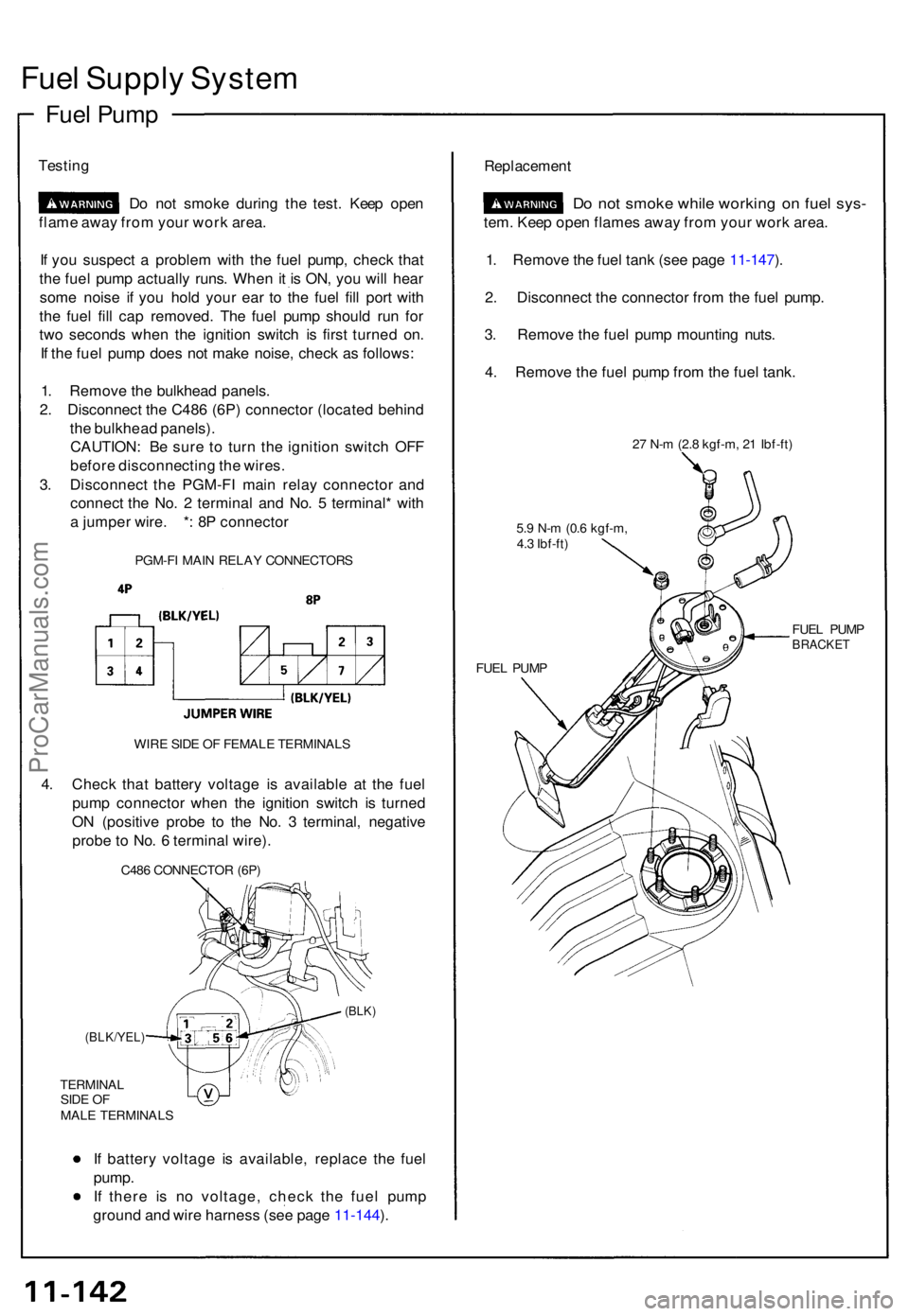
Fuel Suppl y Syste m
Fuel Pum p
Testin g
Do no t smok e durin g th e test . Kee p ope n
flam e awa y fro m you r wor k area .
I f yo u suspec t a proble m wit h th e fue l pump , chec k tha t
th e fue l pum p actuall y runs . Whe n it i s ON , yo u wil l hea r
som e nois e i f yo u hol d you r ea r t o th e fue l fil l por t wit h
th e fue l fil l ca p removed . Th e fue l pum p shoul d ru n fo r
tw o second s whe n th e ignitio n switc h i s firs t turne d on .
I f th e fue l pum p doe s no t mak e noise , chec k a s follows :
1 . Remov e th e bulkhea d panels .
2 . Disconnec t th e C48 6 (6P ) connecto r (locate d behin d
th e bulkhea d panels) .
CAUTION : B e sur e t o tur n th e ignitio n switc h OF F
befor e disconnectin g th e wires .
3 . Disconnec t th e PGM-F I mai n rela y connecto r an d
connec t th e No . 2 termina l an d No . 5 terminal * wit h
a jumpe r wire . * : 8 P connecto r
PGM-FI MAI N RELA Y CONNECTOR S
WIR E SID E O F FEMAL E TERMINAL S
4. Chec k tha t batter y voltag e i s availabl e a t th e fue l
pum p connecto r whe n th e ignitio n switc h i s turne d
O N (positiv e prob e t o th e No . 3 terminal , negativ e
prob e t o No . 6 termina l wire) .
C486 CONNECTO R (6P )
(BLK )
(BLK/YEL )
TERMINAL
SID E O F
MAL E TERMINAL S
If batter y voltag e i s available , replac e th e fue l
pump .
I f ther e i s n o voltage , chec k th e fue l pum p
groun d an d wir e harnes s (se e pag e 11-144 ).
Replacemen t
Do no t smok e whil e workin g o n fue l sys -
tem. Kee p ope n flame s awa y fro m you r wor k area .
1 . Remov e th e fue l tan k (se e pag e 11-147 ).
2 . Disconnec t th e connecto r fro m th e fue l pump .
3 . Remov e th e fue l pum p mountin g nuts .
4 . Remov e th e fue l pum p fro m th e fue l tank .
27 N- m (2. 8 kgf-m , 2 1 Ibf-ft )
5. 9 N- m (0. 6 kgf-m ,
4. 3 Ibf-ft )
FUE L PUM P FUE
L PUM P
BRACKE T
ProCarManuals.com
Page 264 of 1640
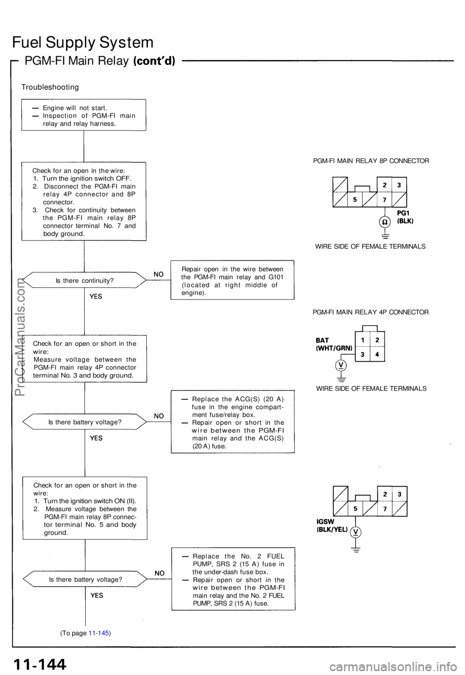
Fuel Suppl y Syste m
PGM-F I Mai n Rela y
Troubleshootin g
Is ther e continuity ?
Chec k fo r a n ope n o r shor t i n th e
wire :Measur e voltag e betwee n th e
PGM-F I mai n rela y 4 P connecto r
terminal No . 3 an d bod y ground .
Is ther e batter y voltage ?
Chec k fo r a n ope n o r shor t i n th e
wire :
1. Tur n th e ignitio n switc h O N (II) .2. Measur e voltag e betwee n th e
PGM-F I mai n rela y 8 P connec -
tor termina l No . 5 an d bod yground .
PGM-FI MAI N RELA Y 8 P CONNECTO R
WIR E SID E O F FEMAL E TERMINAL S
Repai r ope n i n th e wir e betwee n
th e PGM-F I mai n rela y an d G10 1
(locate d a t righ t middl e o fengine) .
PGM-FI MAI N RELA Y 4 P CONNECTO R
Replac e th e ACG(S ) (2 0 A )
fus e i n th e engin e compart -
men t fuse/rela y box .
Repai r ope n o r shor t i n th e
wir e betwee n th e PGM-F Imain rela y an d th e ACG(S )
(2 0 A ) fuse . WIR
E SID E O F FEMAL E TERMINAL S
I s ther e batter y voltage ?
(T o pag e 11-145 ) Replac
e th e No . 2 FUE L
PUMP , SR S 2 (1 5 A ) fus e i n
th e under-das h fus e box .
Repai r ope n o r shor t i n th e
wir e betwee n th e PGM-F Imain rela y an d th e No . 2 FUE L
PUMP , SR S 2 (1 5 A ) fuse .
Engin
e wil l no t start .
Inspectio n o f PGM-F I mai n
rela y an d rela y harness .
Chec k fo r a n ope n in th e wire :
1. Tur n th e ignitio n switc h OFF .2. Disconnec t th e PGM-F I mai n
rela y 4 P connecto r an d 8 P
connector .
3 . Chec k fo r continuit y betwee n
th e PGM-F I mai n rela y 8 P
connecto r termina l No . 7 an d
body ground .
ProCarManuals.com
Page 987 of 1640
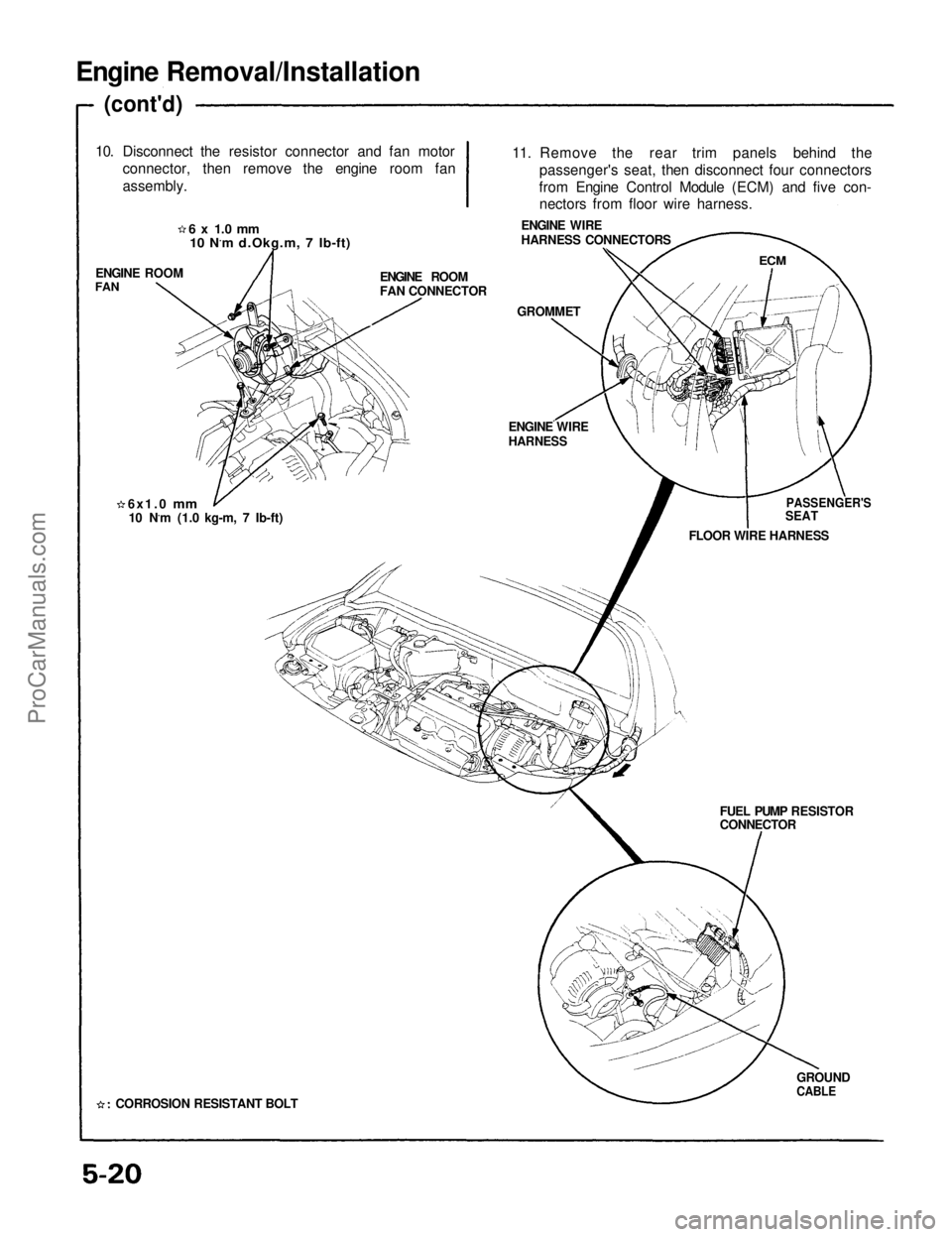
Engine Removal/Installation
(cont'd)
10. Disconnect the resistor connector and fan motor connector, then remove the engine room fan
assembly.
ENGINE ROOM
FAN
ENGINE ROOM
FAN CONNECTOR
GROMMET
11. Remove the rear trim panels behind the
passenger's seat, then disconnect four connectors
from Engine Control Module (ECM) and five con- nectors from floor wire harness.
ENGINE WIRE
HARNESS CONNECTORS
ECM
PASSENGER'S
SEAT
FLOOR WIRE HARNESS
ENGINE WIRE
HARNESS
FUEL PUMP RESISTOR
CONNECTORGROUND
CABLE
6x1.0
mm
10 N.m (1.0 kg-m, 7 Ib-ft)
CORROSION RESISTANT BOLT
6 x 1.0 mm
10 N.m d.Okg.m, 7 Ib-ft)ProCarManuals.com
Page 998 of 1640
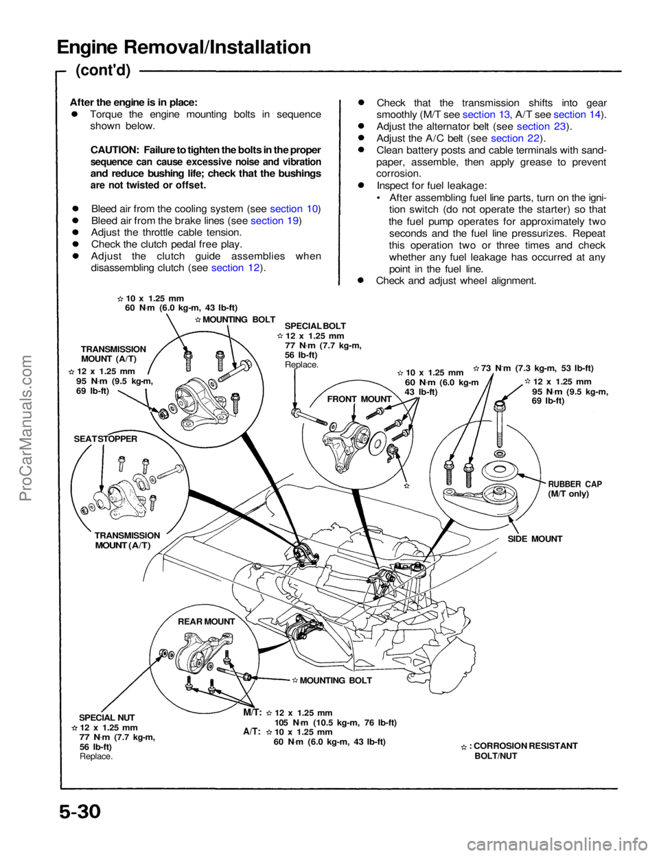
Engine Removal/Installation
(cont'd)
Torque the engine mounting bolts in sequenceshown below.
CAUTION: Failure to tighten the bolts in the proper
sequence can cause excessive noise and vibration
and reduce bushing life; check that the bushings
are not twisted or offset.
Bleed air from the cooling system (see section 10)
Bleed air from the brake lines (see section 19)
Adjust the throttle cable tension.
Check the clutch pedal free play.
Adjust the clutch guide assemblies when
disassembling clutch (see section 12). Check that the transmission shifts into gear
smoothly (M/T see section 13, A/T see section 14).
Adjust the alternator belt (see section 23).
Adjust the A/C belt (see section 22).
Clean battery posts and cable terminals with sand-
paper, assemble, then apply grease to prevent
corrosion.
Inspect for fuel leakage:
• After assembling fuel line parts, turn on the igni- tion switch (do not operate the starter) so that
the fuel pump operates for approximately two seconds and the fuel line pressurizes. Repeat
this operation two or three times and check whether any fuel leakage has occurred at any
point in the fuel line.
Check and adjust wheel alignment.
10 x
1.25
mm
60 N .
m (6.0 kg-m, 43 Ib-ft)
MOUNTING BOLT SPECIAL BOLT
12 x
1.25
mm
77 N .
m
(7.7 kg-m,
56 Ib-ft)
Replace.
10 x
1.25
mm
60 N .
m
(6.0 kg-m
43 Ib-ft) 73 N.m (7.3 kg-m, 53 Ib-ft)
12 x
1.25
mm
95 N .
m
(9.5 kg-m,
69 Ib-ft)
RUBBER CAP
(M/T only)
SIDE MOUNT
: CORROSION RESISTANT
BOLT/NUT
12 x
1.25
mm
105 N .
m (10.5 kg-m, 76 Ib-ft)
10 x
1.25
mm
60 N .
m (6.0 kg-m, 43 Ib-ft) MOUNTING BOLT FRONT MOUNT
TRANSMISSION
MOUNT (A/T)
12 x
1.25
mm
95 N .
m
(9.5 kg-m,
69 Ib-ft)
SEAT STOPPER
TRANSMISSION
MOUNT (A/T)
REAR MOUNT
SPECIAL NUT
12 x
1.25
mm
77 N .
m
(7.7 kg-m,
56 Ib-ft)
Replace.
M/T:
A/T:
After the engine is in place:ProCarManuals.com
Page 1048 of 1640
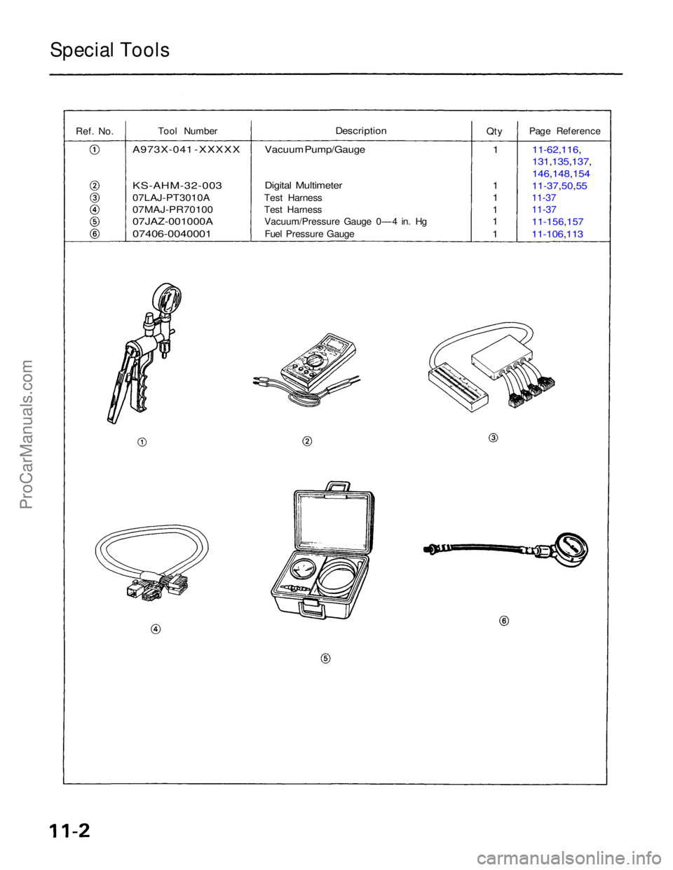
Special Tools
Ref. No.
Tool Number
A973X-041 -XXXXX
KS-AHM-32-003
07LAJ-PT3010A
07MAJ-PR70100
07JAZ-001000A
07406-0040001
Page Reference
11-62,116,
131,135,137,
146,148,154
11-37,50,55
11-37
11-37
11-156,157
11-106,113
Description
Vacuum Pump/Gauge
Digital Multimeter
Test Harness
Test Harness Vacuum/Pressure Gauge 0—4 in. Hg
Fuel Pressure Gauge
Qty
1
1
1
1
1
1ProCarManuals.com