radiator ACURA NSX 1991 Service Repair Manual
[x] Cancel search | Manufacturer: ACURA, Model Year: 1991, Model line: NSX, Model: ACURA NSX 1991Pages: 1640, PDF Size: 60.48 MB
Page 72 of 1640
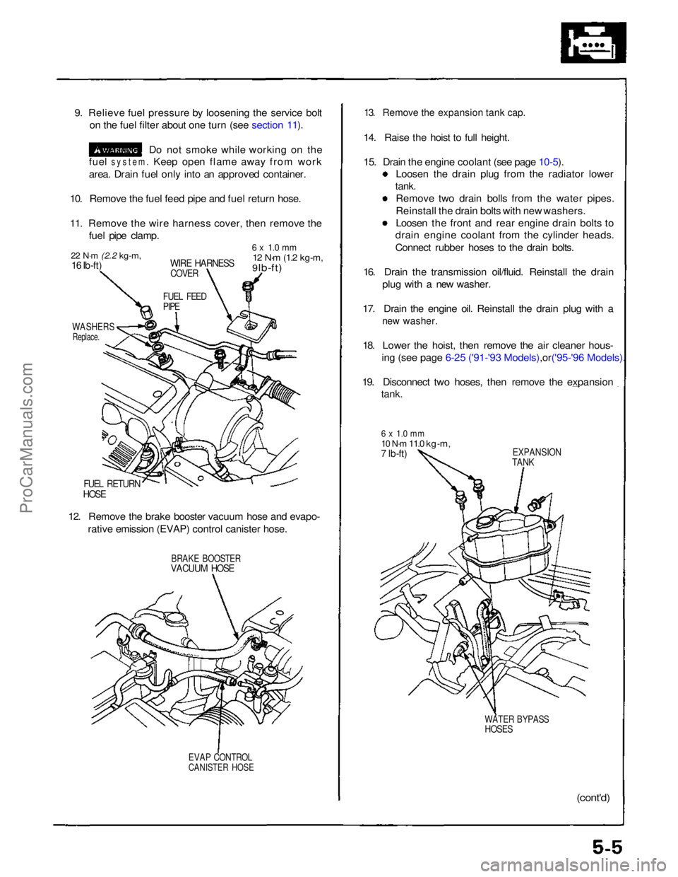
9. Relieve fuel pressure by loosening the service bolt
on the fuel filter about one turn (see section 11).
Do not smoke while working on the
fuel
system.
Keep open flame away from work
area. Drain fuel only into an approved container.
10. Remove the fuel feed pipe and fuel return hose.
11. Remove the wire harness cover, then remove the fuel pipe clamp.
22 N·m
(2.2 kg-m,
16 Ib-ft)
WIRE HARNESS
COVER
6 x 1.0 mm
12 N·m
(1.2 kg-m,
9 lb-ft)
FUEL FEED
PIPE
WASHERS
Replace.
FUEL RETURN
HOSE
12. Remove the brake booster vacuum hose and evapo- rative emission (EVAP) control canister hose.
BRAKE BOOSTER
VACUUM HOSE
EVAP CONTROL
CANISTER HOSE
13. Remove the expansion tank cap.
14. Raise the hoist to full height.
15. Drain the engine coolant (see page
10-5).
Loosen the drain plug from the radiator lower
tank. Remove two drain bolls from the water pipes.
Reinstall the drain bolts with new washers.
Loosen the front and rear engine drain bolts to
drain engine coolant from the cylinder heads.
Connect rubber hoses to the drain bolts.
16. Drain the transmission oil/fluid. Reinstall the drain plug with a new washer.
17. Drain the engine oil. Reinstall the drain plug with a
new washer.
18. Lower the hoist, then remove the air cleaner hous-
ing (see page 6-25 ('91-'93 Mode ls),or('95-'96 Models).
19. Disconnect two hoses, then remove the expansion
tank.
6 x 1.0 mm
10 N·m
11.0 kg-m,
7 lb-ft)
EXPANSION
TANK
WATER BYPASS
HOSES
(cont'd)ProCarManuals.com
Page 73 of 1640
Engine Removal/Installation
Removal
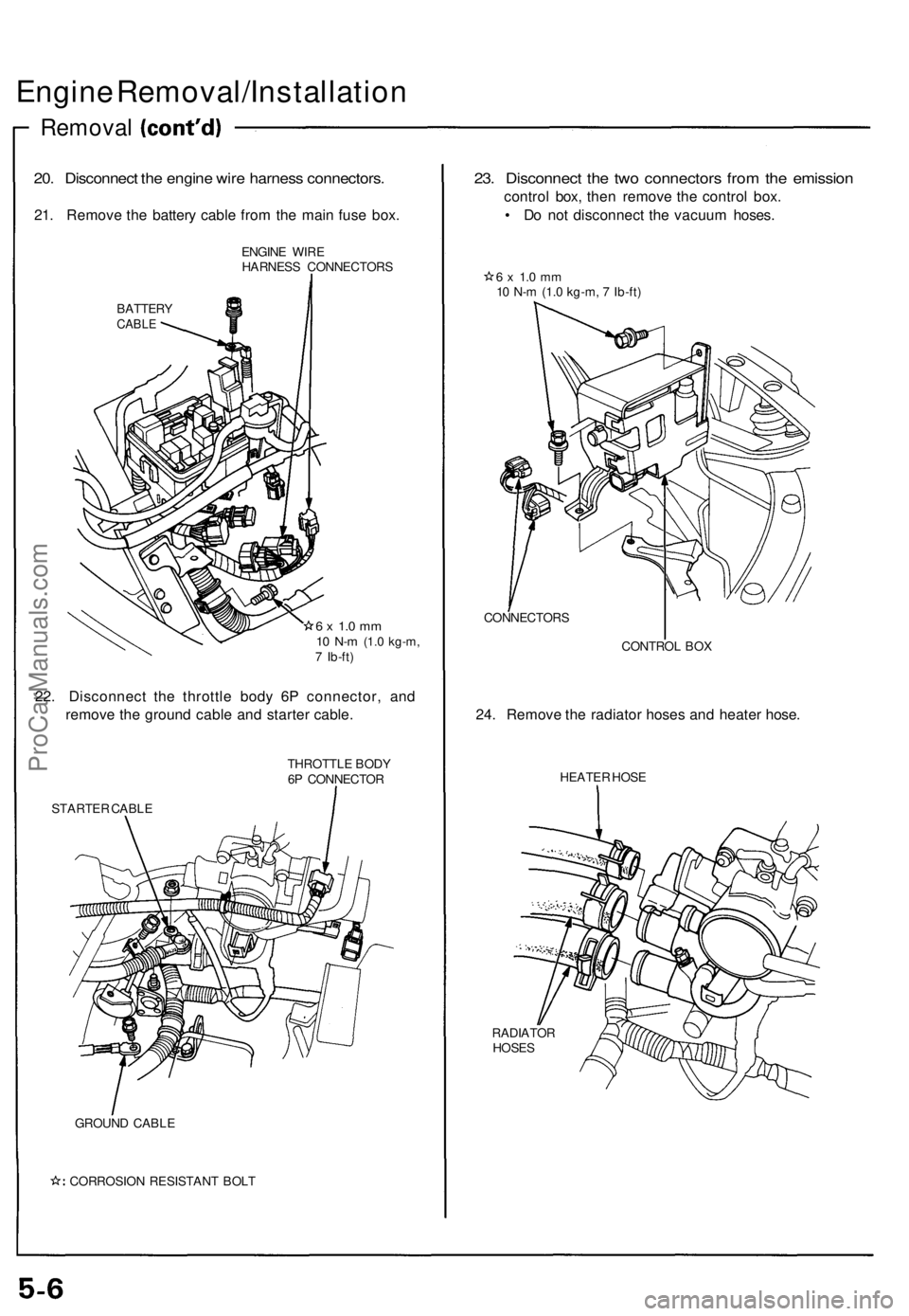
20. Disconnect the engine wire harness connectors.
21. Remove the battery cable from the main fuse box.
ENGINE WIRE
HARNESS CONNECTORS
BATTERY
CABLE
6 x 1.0 mm
10 N-m
(1.0 kg-m,
7 Ib-ft)
22. Disconnect the throttle body 6P connector, and
remove the ground cable and starter cable.
STARTER CABLE
THROTTLE BODY
6P CONNECTOR
GROUND CABLE
CORROSION RESISTANT BOLT
23. Disconnect the two connectors from the emission
control box, then remove the control box.
• Do not disconnect the vacuum hoses.
6 x 1.0 mm
10 N-m (1.0 kg-m, 7 Ib-ft)
CONNECTORS
CONTROL BOX
24. Remove the radiator hoses and heater hose.
HEATER HOSE
RADIATOR
HOSESProCarManuals.com
Page 100 of 1640
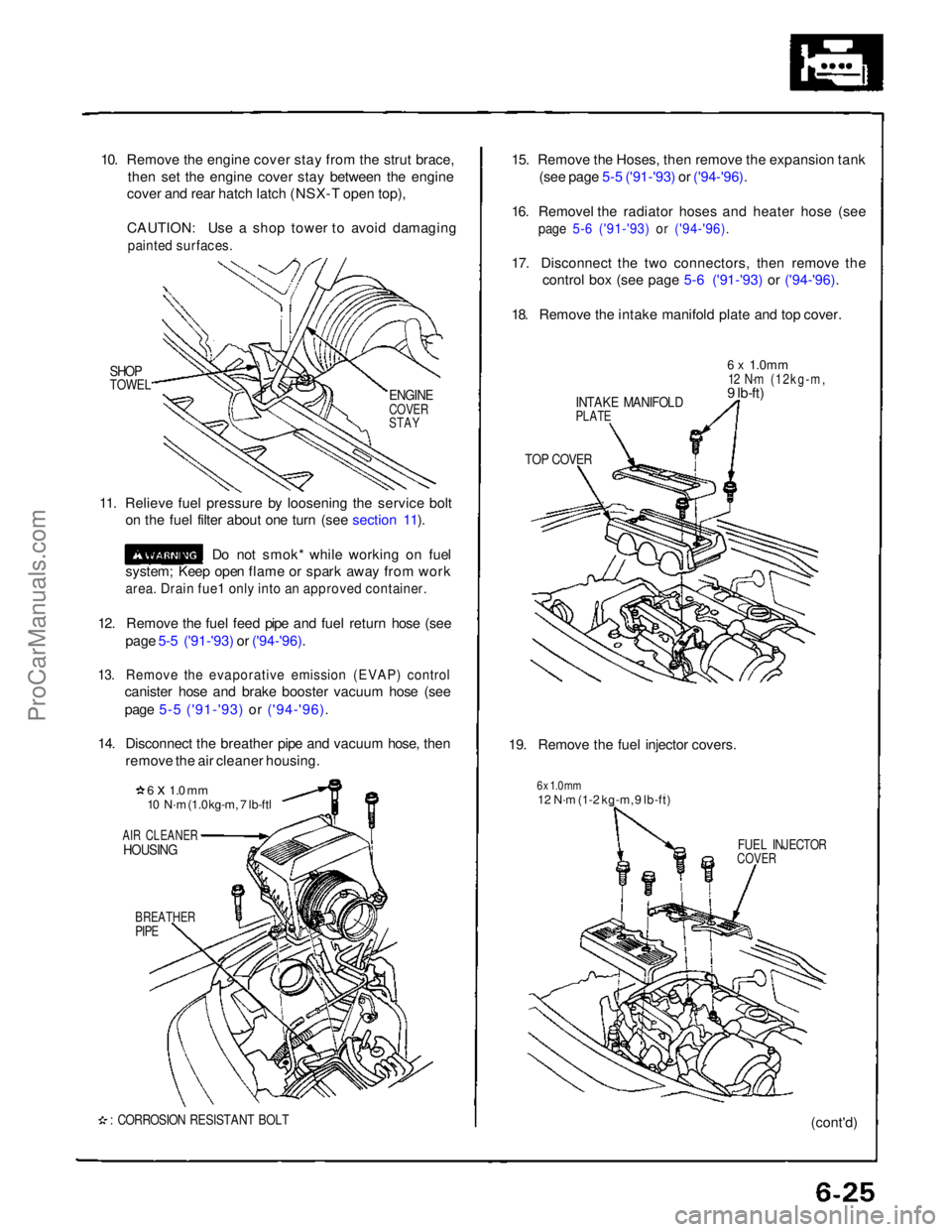
10. Remove the engine cover stay from the strut brace,
then set the engine cover stay between the engine
cover and rear hatch latch (NSX-T open top),
CAUTION: Use a shop tower to avoid damaging
painted surfaces.
SHOP
TOWEL
11. Relieve fuel pressure by loosening the service bolt on the fuel filter about one turn (see section 11).
Do not smok* while working on fuel
system; Keep open flame or spark away from work
area. Drain fue1 only into an approved container.
12. Remove the fuel feed pipe and fuel return hose (see page 5-5 ('91-'93) or ('94-'96).
13. Remove the evaporative emission (EVAP) control
canister hose and brake booster vacuum hose (see
page 5-5 ('91-'93) or ('94-'96).
14. Disconnect the breather pipe and vacuum hose, then remove the air cleaner housing.
6 x 1.0 mm
10 N·m (1.0 kg-m, 7 lb-ftl
AIR CLEANER
HOUSING
BREATHER
PIPE
: CORROSION RESISTANT BOLT
15. Remove the Hoses, then remove the expansion tank
(see page 5-5 ('91-'93) or ('94-'96).
16. Removel the radiator hoses and heater hose (see
page 5-6 ('91-'93) or ('94-'96).
17. Disconnect the two connectors, then remove the
control box (see page 5-6 ('91-'93) or ('94-'96).
18. Remove the intake manifold plate and top cover.
INTAKE MANIFOLD
PLATE
6 x
1.0mm
12 N·m (12kg-m,
9 lb-ft)
TOP COVER
19. Remove the fuel injector covers.
6 x 1.0 mm
12 N·m (1-2 kg-m, 9 lb-ft)
FUEL INJECTOR
COVER
(cont'd)
ENGINE
COVER
STAYProCarManuals.com
Page 162 of 1640
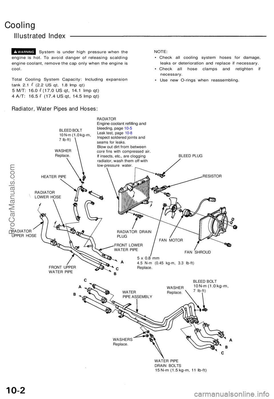
Cooling
Illustrated Index
Syste m is unde r hig h pressur e whe n th e
engin e i s hot . T o avoi d dange r o f releasin g scaldin g
engin e coolant , remov e th e ca p onl y whe n th e engin e i s
cool .
Tota l Coolin g Syste m Capacity : Includin g expansio n
tank 2. 1 (2. 2 U S qt . 1. 8 Im p qt )
5 M/T : 16. 0 (17. 0 US qt , 14. 1 Imp qt )
4 A/T : 16. 5 (17. 4 US qt , 14. 5 Imp qt )
NOTE :
• Chec k al l coolin g syste m hose s fo r damage ,
leak s o r deterioratio n an d replac e i f necessary .
• Chec k al l hos e clamp s an d retighte n i f
necessary .
• Us e ne w O-ring s whe n reassembling .
Radiator, Wate r Pipe s an d Hoses :
BLEED BOL T10 N- m (1. 0 kg-m ,7 Ib-ft )
WASHE RReplace .
HEATER PIP E
RADIATO R
LOWE R HOS E
RADIATO R
UPPE R HOS E
RADIATO REngine coolan t refillin g an dbleeding , pag e 10- 5Leak test , pag e 10- 8Inspec t soldere d joint s an dseam s fo r leaks .Blow ou t dir t fro m betwee ncore fin s wit h compresse d air .If insects , etc. , ar e cloggin gradiator, was h the m of f wit hlow-pressur e water . BLEE
D PLU G
RESISTO R
RADIATO R DRAI N
PLU G
FRON T LOWE R
WATE R PIP E
FRON T UPPE R
WATE R PIP E FA
N SHROU D
5 x 0. 8 m m4.5 N- m (0.4 5 kg-m , 3. 3 Ib-ft )
Replace .
BLEED BOL T
10 N- m (1. 0 kg-m ,7 Ib-ft )
WASHER S
Replace .
WATER PIP E
DRAI N BOLT S
15 N- m (1. 5 kg-m , 1 1 Ib-ft )
WATE RPIPE ASSEMBL YWASHE
RReplace .
FAN MOTO R
ProCarManuals.com
Page 164 of 1640
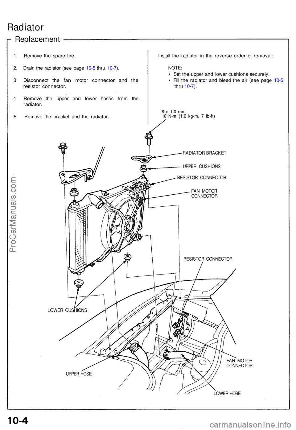
Radiator
Replacemen t
1. Remov e th e spar e tire .
2 . Drai n th e radiato r (se e pag e 10- 5 thr u 10-7 ).
3 . Disconnec t th e fa n moto r connecto r an d th e
resisto r connector .
4. Remov e th e uppe r an d lowe r hose s fro m th e
radiator .
5. Remov e th e bracke t an d th e radiator . Instal
l th e radiato r i n th e revers e orde r o f removal :
NOTE:
• Se t th e uppe r an d lowe r cushion s securely .
• Fil l th e radiato r an d blee d th e ai r (se e pag e 10- 5
thr u 10-7 ).
6 x 1. 0 m m10 N- m (1. 0 kg-m , 7 Ib-ft )
RADIATO R BRACKE T
UPPE R CUSHION S
RESISTO R CONNECTO R
FA N MOTO R
CONNECTO R
RESISTO R CONNECTO R
LOWER CUSHION S
FAN MOTO R
CONNECTO R
UPPE R HOS E
LOWER HOS E
ProCarManuals.com
Page 165 of 1640
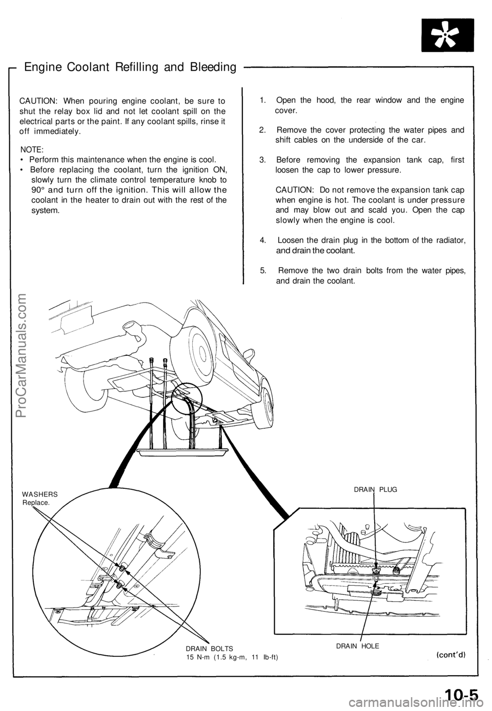
Engine Coolant Refilling and Bleeding
CAUTION: When pouring engine coolant, be sure to
shut the relay box lid and not let coolant spill on the
electrical parts or the paint. If any coolant spills, rinse it
off immediately.
NOTE:
• Perform this maintenance when the engine is cool.
• Before replacing the coolant, turn the ignition ON,
slowly turn the climate control temperature knob to
90° and turn off the ignition. This will allow the
coolant in the heater to drain out with the rest of the
system.
1. Open the hood, the rear window and the engine
cover.
2. Remove the cover protecting the water pipes and
shift cables on the underside of the car.
3. Before removing the expansion tank cap, first
loosen the cap to lower pressure.
CAUTION: Do not remove the expansion tank cap
when engine is hot. The coolant is under pressure
and may blow out and scald you. Open the cap
slowly when the engine is cool.
4. Loosen the drain plug in the bottom of the radiator,
and drain the coolant.
5. Remove the two drain bolts from the water pipes,
and drain the coolant.
WASHERS
Replace.
DRAIN BOLTS
15 N-m (1.5 kg-m, 11 Ib-ft)
DRAIN HOLE
DRAIN PLUGProCarManuals.com
Page 166 of 1640
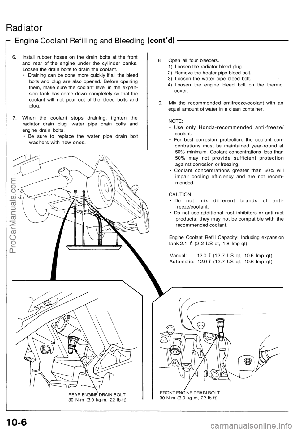
Radiator
Engine Coolan t Refillin g an d Bleedin g
6. Instal l rubbe r hose s o n th e drai n bolt s a t th e fron t
an d rea r of the engin e unde r th e cylinde r banks .
Loose n th e drai n bolt s t o drai n th e coolant .
• Drainin g ca n b e don e mor e quickl y i f al l th e blee d
bolt s an d plu g ar e als o opened . Befor e openin g
them , mak e sur e th e coolan t leve l i n th e expan -
sio n tan k ha s com e dow n completel y s o tha t th e
coolan t wil l no t pou r ou t o f th e blee d bolt s an d
plug .
7. Whe n th e coolan t stop s draining , tighte n th e
radiato r drai n plug , wate r pip e drai n bolt s an d
engin e drai n bolts .
• B e sur e t o replac e th e wate r pip e drai n bol t
washer s wit h ne w ones .
REAR ENGIN E DRAI N BOL T
3 0 N- m (3. 0 kg-m , 2 2 Ib-ft )
8. Ope n al l fou r bleeders .
1 ) Loose n th e radiato r blee d plug .
2 ) Remov e th e heate r pip e blee d bolt .
3 ) Loose n th e wate r pip e blee d bolt .
4 ) Loose n th e engin e blee d bol t o n th e therm o
cover.
9. Mi x th e recommende d antifreeze/coolan t wit h a n
equa l amoun t o f wate r i n a clea n container .
NOTE:
• Us e onl y Honda-recommende d anti-freeze /
coolant.
• Fo r bes t corrosio n protection , th e coolan t con -
centration s mus t b e maintaine d year-roun d a t
50 % minimum . Coolan t concentration s les s tha n
50 % ma y no t provid e sufficien t protectio n
agains t corrosio n o r freezing .
• Coolan t concentration s greate r tha n 60 % wil l
impai r coolin g efficienc y an d ar e no t recom -
mended.
CAUTION :
• D o no t mi x differen t brand s o f anti -
freeze/coolant .
• D o no t us e additiona l rus t inhibitor s o r anti-rus t
products ; the y ma y no t b e compatibl e wit h th e
recommende d coolant .
Engin e Coolan t Refil l Capacity : Includin g expansio n
tank 2. 1 (2. 2 U S qt , 1. 8 Im p qt )
Manual : 12. 0 (12. 7 U S qt , 10. 6 Im p qt )
Automatic : 12. 0 (12. 7 U S qt , 10. 6 Im p qt )
FRON T ENGIN E DRAI N BOL T30 N- m (3. 0 kg-m , 2 2 Ib-ft )
ProCarManuals.com
Page 438 of 1640
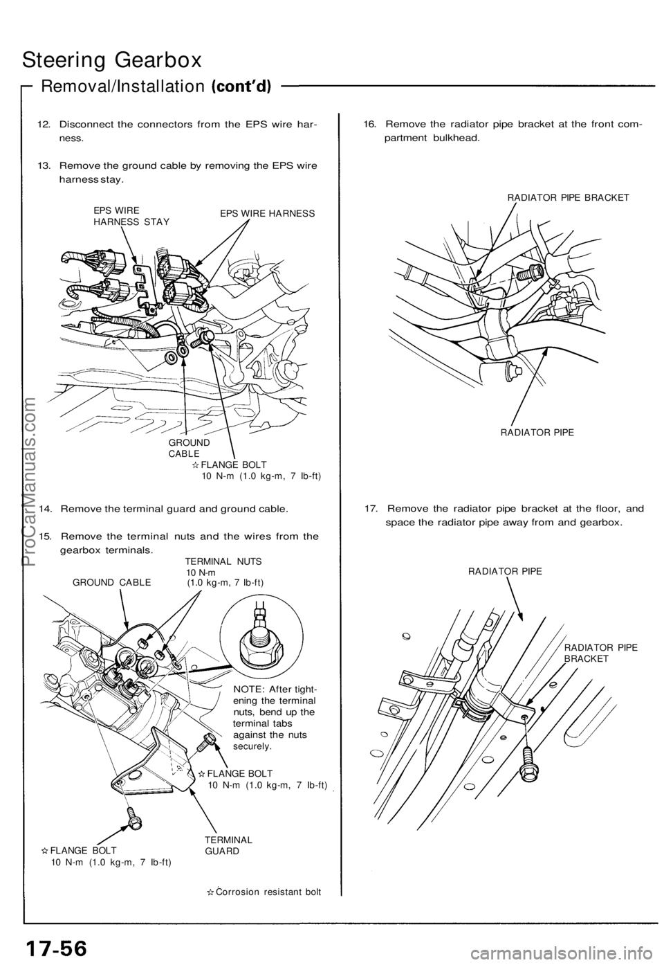
Steering Gearbo x
Removal/Installatio n
12. Disconnec t th e connector s fro m th e EP S wir e har -
ness .
13. Remov e th e groun d cabl e b y removin g th e EP S wir e
harnes s stay .
EPS WIR E
HARNES S STA Y EP
S WIR E HARNES S
GROUN D
CABLEFLANG E BOL T
1 0 N- m (1. 0 kg-m , 7 Ib-ft )
14. Remov e th e termina l guar d an d groun d cable .
15 . Remov e th e termina l nut s an d th e wire s fro m th e
gearbo x terminals .
TERMINAL NUT S10 N- mGROUN D CABL E (1.0 kg-m , 7 Ib-ft )
FLANG E BOL T
1 0 N- m (1. 0 kg-m , 7 Ib-ft )
NOTE : Afte r tight -ening th e termina lnuts, ben d u p th etermina l tab sagains t th e nut ssecurely .
FLANG E BOL T
1 0 N- m (1. 0 kg-m , 7 Ib-ft )
TERMINA L
GUAR D
Corrosio n resistan t bol t
16. Remov e th e radiato r pip e bracke t a t th e fron t com -
partmen t bulkhead .
RADIATOR PIP E BRACKE T
RADIATO R PIP E
17. Remov e th e radiato r pip e bracke t a t th e floor , an d
spac e th e radiato r pip e awa y fro m an d gearbox .
RADIATO R PIP E
RADIATO R PIP E
BRACKE T
ProCarManuals.com
Page 439 of 1640
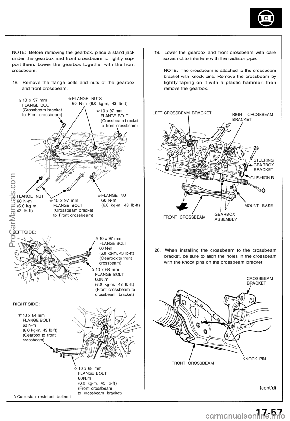
NOTE: Before removing the gearbox, place a stand jack
under the gearbox and front crossbeam to lightly sup-
port them. Lower the gearbox together with the front
crossbeam.
18. Remove the flange bolts and nuts of the gearbox
and front crossbeam.
10 x 97 mm
FLANGE BOLT
(Crossbeam bracket
to Front crossbeam)
FLANGE NUTS
60 N-m (6.0 kg-m, 43 Ib-ft)
10 x 97 mm
FLANGE BOLT
(Crossbeam bracket
to front crossbeam)
/
FLANGE NUT
60 N-m
(6.0 kg-m,
43 Ib-ft)
LEFT SIDE:
10 x 97 mm
FLANGE BOLT
(Crossbeam bracket
to Front crossbeam)
FLANGE NUT
60 N-m
(6.0 kg-m, 43 Ib-ft)
10 x 97 mm
FLANGE BOLT
60 N-m
(6.0 kg-m, 43 Ib-ft)
(Gearbox to front
crossbeam)
10 x 68 mm
FLANGE BOLT
60N.m
(6.0 kg-m. 43 Ib-ft)
(Front crossbeam to
crossbeam bracket)
RIGHT SIDE:
10 x 84 mm
FLANGE BOLT
60 N-m
(6.0 kg-m, 43 Ib-ft)
(Gearbox to front
crossbeam)
Corrosion resistant bolt/nut
10 x 68 mm
FLANGE BOLT
60N.m
(6.0 kg-m, 43 Ib-ft)
(Front crossbeam
to crossbeam bracket)
19. Lower the gearbox and front crossbeam with care
so as not to interfere with the radiator pipe.
NOTE: The crossbeam is attached to the crossbeam
bracket with knock pins. Remove the crossbeam by
lightly taping on it with a plastic hammer, then
remove the gearbox.
LEFT CROSSBEAM BRACKET
RIGHT CROSSBEAM
BRACKET
STEERING
GEARBOX
BRACKET
CUSHION B
MOUNT BASE
FRONT CROSSBEAM
GEARBOX
ASSEMBLY
20. When installing the crossbeam to the crossbeam
bracket, be sure to align the holes in the crossbeam
with the knock pins on the crossbeam bracket.
CROSSBEAM
BRACKET
FRONT CROSSBEAM
KNOCK PINProCarManuals.com
Page 683 of 1640
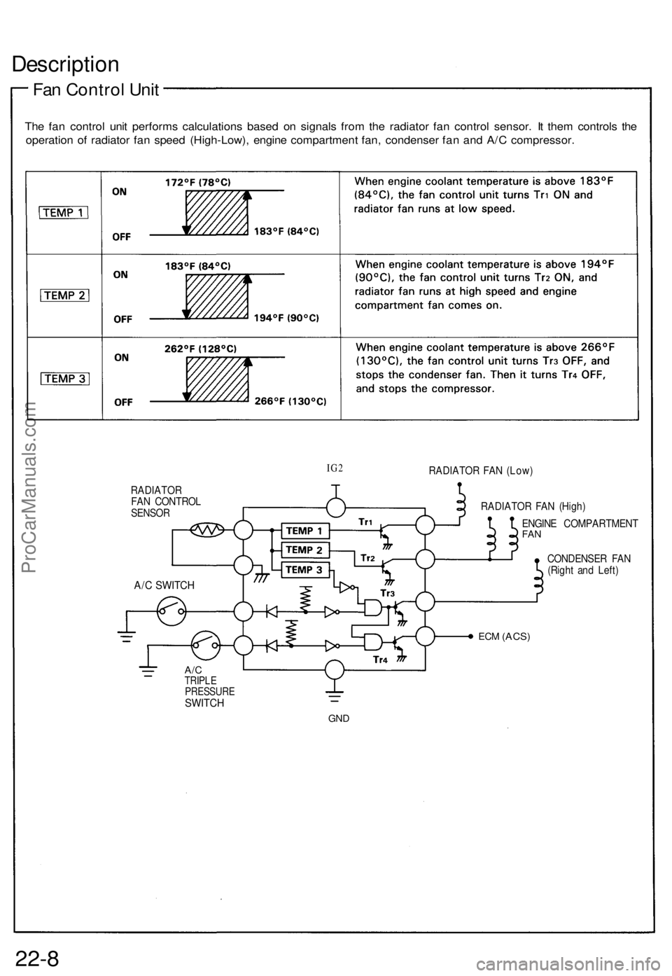
Description
Fan Control Unit
The fan control unit performs calculations based on signals from the radiator fan control sensor. It them controls the
operation of radiator fan speed (High-Low), engine compartment fan, condenser fan and A/C compressor.
IG2
RADIATOR FAN (Low)
RADIATOR
FAN CONTROL
SENSOR
RADIATOR FAN (High)
ENGINE COMPARTMENT
FAN
CONDENSER FAN
(Right and Left)
ECM
(ACS)
A/C
TRIPLE
PRESSURE
SWITCH
GND
22-8
A/C SWITCHProCarManuals.com