ECU ACURA NSX 1997 Service Owners Manual
[x] Cancel search | Manufacturer: ACURA, Model Year: 1997, Model line: NSX, Model: ACURA NSX 1997Pages: 1503, PDF Size: 57.08 MB
Page 1488 of 1503

Airbag/Seat Bel t Tensione r Disposa l
Before scrappin g an y airbag s o r sea t bel t tensioner s
(includin g thos e i n a whol e ca r t o b e scrapped) , th e
airbag s mus t b e deploye d an d th e sea t bel t tensioner s
mus t b e triggered . I f th e ca r i s stil l withi n th e warrant y
period , befor e deployin g th e airbag(s ) o r triggerin g th e
sea t bel t tensioners , th e Acur a Distric t Technica l
Manage r mus t giv e approva l and/o r specia l instruction .
Onl y afte r th e airbag s ar e alread y deploye d o r th e sea t
bel t tensioner s ar e triggere d (a s th e resul t o f vehicl e col -
lision , fo r example) , ca n th e norma l scrappin g proce -
dur e b e done .
I f th e airbag s o r th e sea t bel t tensioner s appea r intac t
(no t deploye d o r triggered) , trea t the m wit h extrem e
caution.
Follow th e procedure , describe d below .
Deployin g th e Airbag(s) : In-vehicl e
NOTE: I f a n SR S vehicl e i s t o b e entirel y scrapped ,
it s airbag s shoul d b e deploye d whil e stil l i n th e
vehicle . Th e airbag s shoul d no t b e considere d a s
salvageabl e part s an d shoul d neve r b e installe d i n
anothe r vehicle .
Confir m tha t eac h airba g assembl y i s
securel y mounted ; otherwise , sever e persona l in -
jur y coul d resul t fro m deployment .
1 . Disconnec t bot h th e negativ e cabl e an d positiv e
cable fro m th e battery .
2. Confir m tha t th e specia l too l i s functionin g properl y
by followin g th e chec k procedur e o n th e labe l o f
the too l o r o n pag e 24-41 .
Driver' s Airbag :
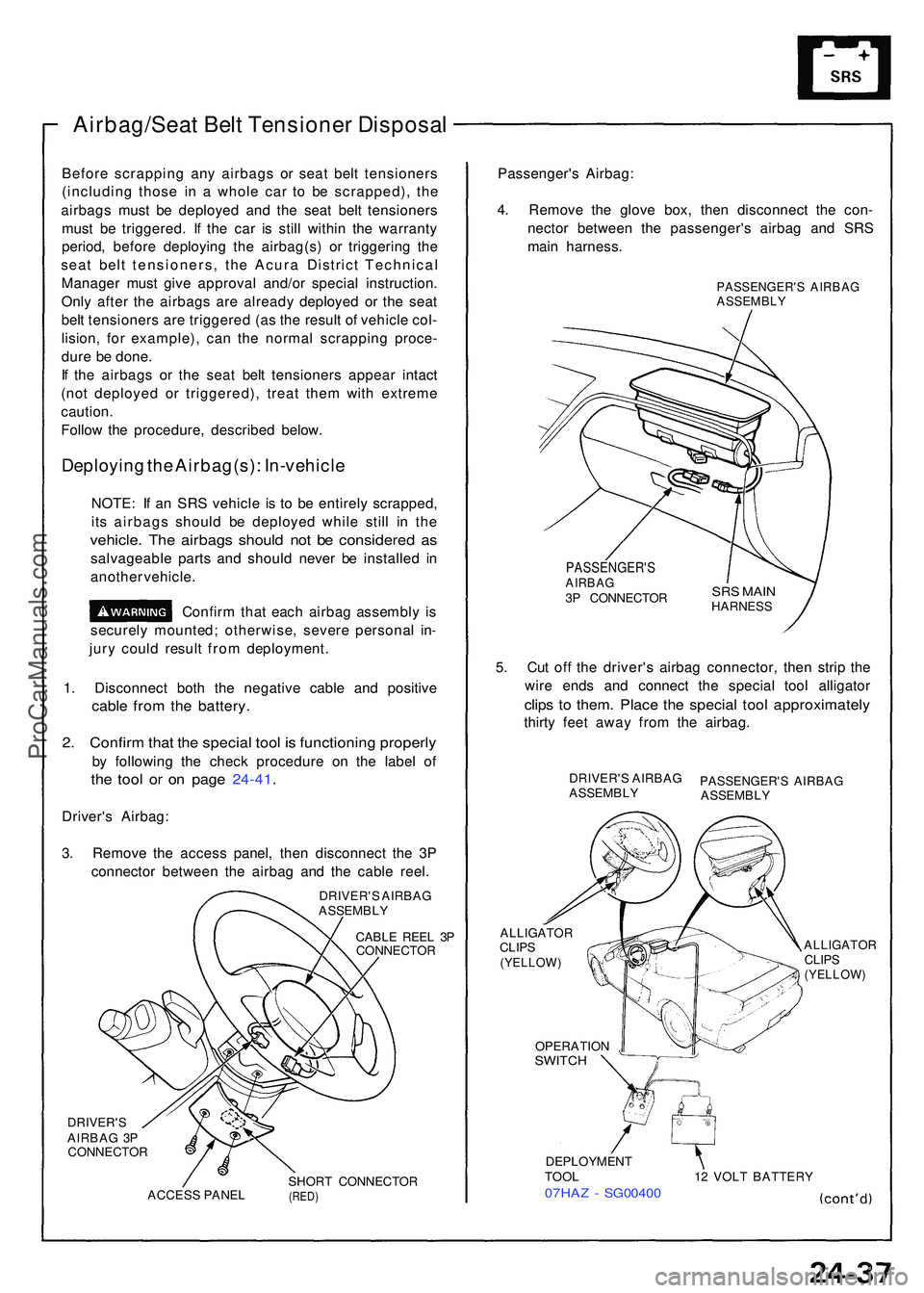
3 . Remov e th e acces s panel , the n disconnec t th e 3 P
connecto r betwee n th e airba g an d th e cabl e reel .
DRIVER' S AIRBA GASSEMBL Y
CABLE REE L 3 P
CONNECTO R
DRIVER'SAIRBAG 3 P
CONNECTO R
ACCES S PANE L SHOR
T CONNECTO R
(RED)
Passenger' s Airbag :
4 . Remov e th e glov e box , the n disconnec t th e con -
necto r betwee n th e passenger' s airba g an d SR S
mai n harness .
PASSENGER' S AIRBA GASSEMBL Y
PASSENGER' SAIRBAG3P CONNECTO R
5. Cu t of f th e driver' s airba g connector , the n stri p th e
wir e end s an d connec t th e specia l too l alligato r
clips t o them . Plac e th e specia l too l approximatel y
thirty fee t awa y fro m th e airbag .
DRIVER' S AIRBA GASSEMBL YPASSENGER' S AIRBA GASSEMBL Y
ALLIGATO RCLIPS(YELLOW )
ALLIGATO RCLIPS(YELLOW )
OPERATIO NSWITCH
DEPLOYMEN T
TOO L 1 2 VOL T BATTER Y
07HAZ - SG0040 0
SRS MAI NHARNES S
ProCarManuals.com
Page 1489 of 1503

Supplemental Restrain t Syste m (SRS )
Airbag/Sea t Bel t Tensione r Disposa l
6. Connec t a 1 2 vol t batter y t o th e tool :
• I f th e gree n ligh t o n th e too l come s on , th e airba g
ignite r circui t i s defectiv e an d canno t b e
deployed . G o t o Damage d Airba g Specia l
Procedure .
• I f th e re d ligh t o n th e too l come s on , th e airba g i s
read y t o b e deployed .
7 . Pus h th e tool' s deploymen t switch . Th e airba g
shoul d deplo y (deploymen t i s bot h highl y audibl e
an d visibl e — a lou d nois e an d rapi d inflatio n o f th e
bag , followe d b y slo w deflation) .
• I f deploymen t happen s an d th e gree n ligh t o n
the too l come s on , continu e wit h thi s procedure .
• I f th e airba g doesn' t deploy , ye t th e gree n ligh t
come s on , it s ignite r i s defective . G o t o Damage d
Airba g Specia l Procedure .
Durin g deployment , th e airba g
assembl y ca n becom e ho t enoug h t o bur n you .
Wai t thirt y minute s afte r deploymen t befor e
touchin g th e assembly .
8 . Dispos e o f th e complet e airba g assembly . N o par t
of it ca n b e reused . Plac e i t i n a sturd y plasti c ba g
an d sea l i t securely .
CAUTION :
• Wea r a fac e shiel d an d glove s whe n handin g a
deploye d airbag .
• Was h you r hand s an d rins e the m wel l wit h
wate r afte r handlin g a deploye d airbag .
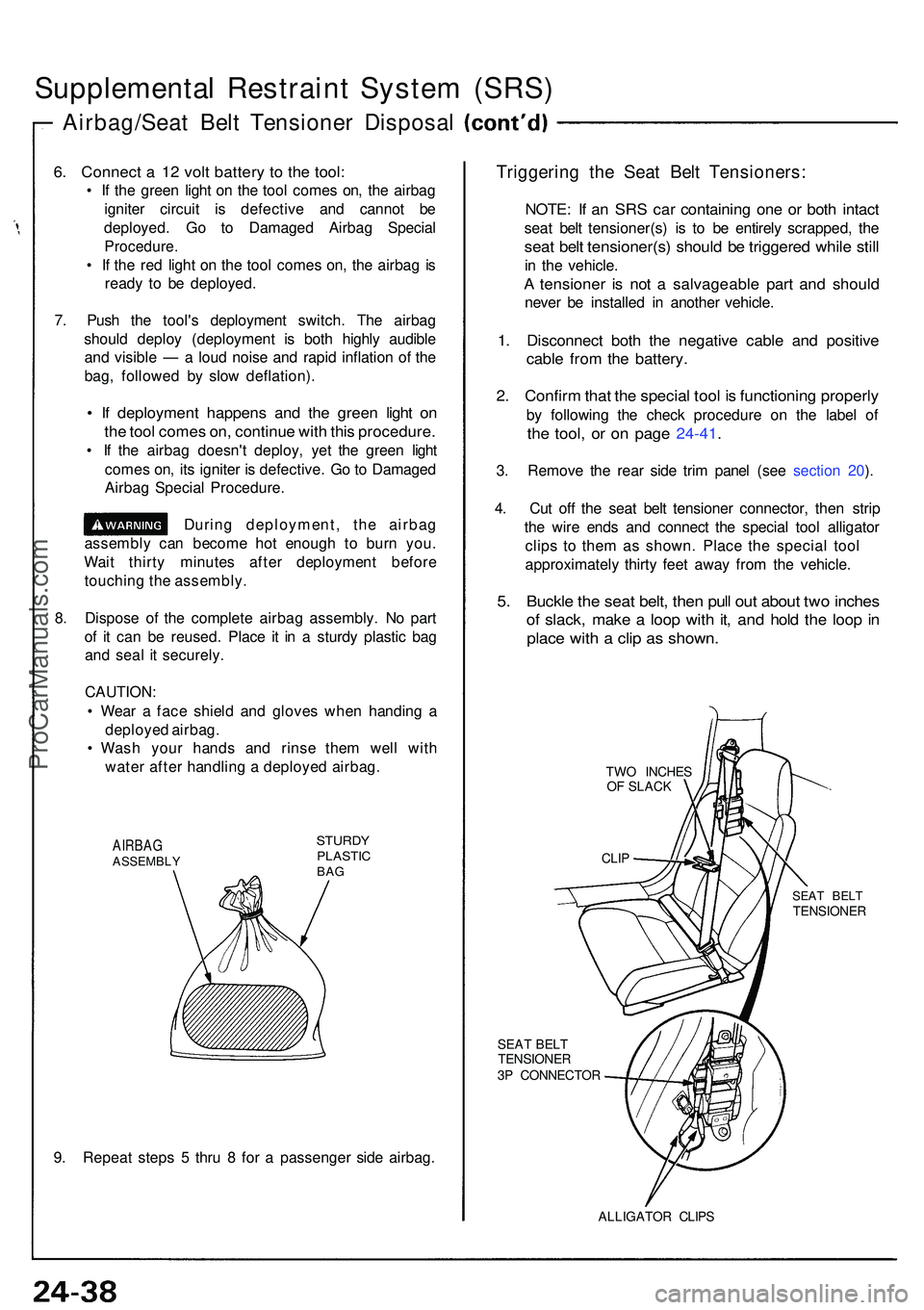
AIRBAGASSEMBL Y
STURDYPLASTI CBAG
9. Repea t step s 5 thru 8 fo r a passenge r sid e airbag .
Triggerin g th e Sea t Bel t Tensioners :
NOTE: I f a n SR S ca r containin g on e o r bot h intac t
seat bel t tensioner(s ) i s t o b e entirel y scrapped , th e
sea t bel t tensioner(s ) shoul d b e triggere d whil e stil l
in th e vehicle .
A tensione r i s no t a salvageabl e par t an d shoul d
never b e installe d i n anothe r vehicle .
1. Disconnec t bot h th e negativ e cabl e an d positiv e
cable fro m th e battery .
2. Confir m tha t th e specia l too l i s functionin g properl y
by followin g th e chec k procedur e o n th e labe l o f
the tool , o r o n pag e 24-41 .
3. Remov e th e rea r sid e tri m pane l (se e sectio n 20 ).
4 . Cu t of f th e sea t bel t tensione r connector , the n stri p
th e wir e end s an d connec t th e specia l too l alligato r
clip s t o the m a s shown . Plac e th e specia l too l
approximatel y thirt y fee t awa y fro m th e vehicle .
5. Buckl e th e sea t belt , the n pul l ou t abou t tw o inche s
of slack , mak e a loo p wit h it , an d hol d th e loo p in
plac e wit h a cli p a s shown .
TWO INCHE S
O F SLAC K
SEAT BEL TTENSIONE R
3 P CONNECTO R
SEAT BEL TTENSIONE R
ALLIGATOR CLIP S
CLIP
ProCarManuals.com
Page 1499 of 1503

Supplemental Restrain t Syste m (SRS )
Dash Senso r Installatio n
CAUTION:
B e sur e t o instal l the harnes s wire s s o tha t the y ar e
no t pinche d o r interferin g wit h othe r ca r parts .
Replac e a senso r i f i t i s dented , cracke d o r deformed .
Fo r th e SR S t o functio n properly , th e righ t an d lef t
sensor s mus t b e installe d o n th e prope r sides .
1 . B e sur e th e batter y cable s ar e disconnected .
2 . Instal l th e senso r securely .
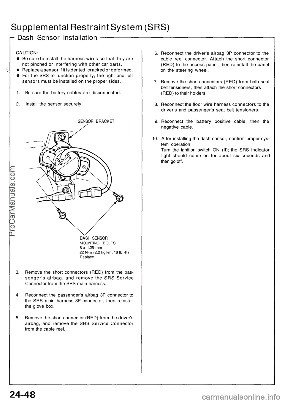
SENSOR BRACKE T
DAS H SENSO R
MOUNTIN G BOLT S8 x 1.2 5 mm22 N- m (2. 2 kgf-m , 1 6 Ibf-ft )Replace .
3. Remov e th e shor t connector s (RED ) fro m th e pas -
senger' s airbag , an d remov e th e SR S Servic e
Connecto r fro m th e SR S mai n harness .
4 . Reconnec t th e passenger' s airba g 3 P connecto r t o
th e SR S mai n harnes s 3 P connector , the n reinstal l
th e glov e box .
5 . Remov e th e shor t connecto r (RED ) fro m th e driver' s
airbag , an d remov e th e SR S Servic e Connecto r
fro m th e cabl e reel . 6
. Reconnec t th e driver' s airba g 3 P connecto r t o th e
cabl e ree l connector . Attac h th e shor t connecto r
(RED ) t o th e acces s panel , the n reinstal l th e pane l
o n th e steerin g wheel .
7 . Remov e th e shor t connector s (RED ) fro m bot h sea t
bel t tensioners , the n attac h th e shor t connector s
(RED ) t o their holders .
8 . Reconnec t th e floo r wir e harnes s connector s t o th e
driver' s an d passenger' s sea t bel t tensioners .
9 . Reconnec t th e batter y positiv e cable , the n th e
negativ e cable .
10 . Afte r installin g th e das h sensor , confir m prope r sys -
te m operation :
Tur n th e ignitio n switc h O N (II) ; th e SR S indicato r
ligh t shoul d com e o n fo r abou t si x second s an d
the n g o off .
ProCarManuals.com