relay ACURA NSX 1997 Service Repair Manual
[x] Cancel search | Manufacturer: ACURA, Model Year: 1997, Model line: NSX, Model: ACURA NSX 1997Pages: 1503, PDF Size: 57.08 MB
Page 36 of 1503
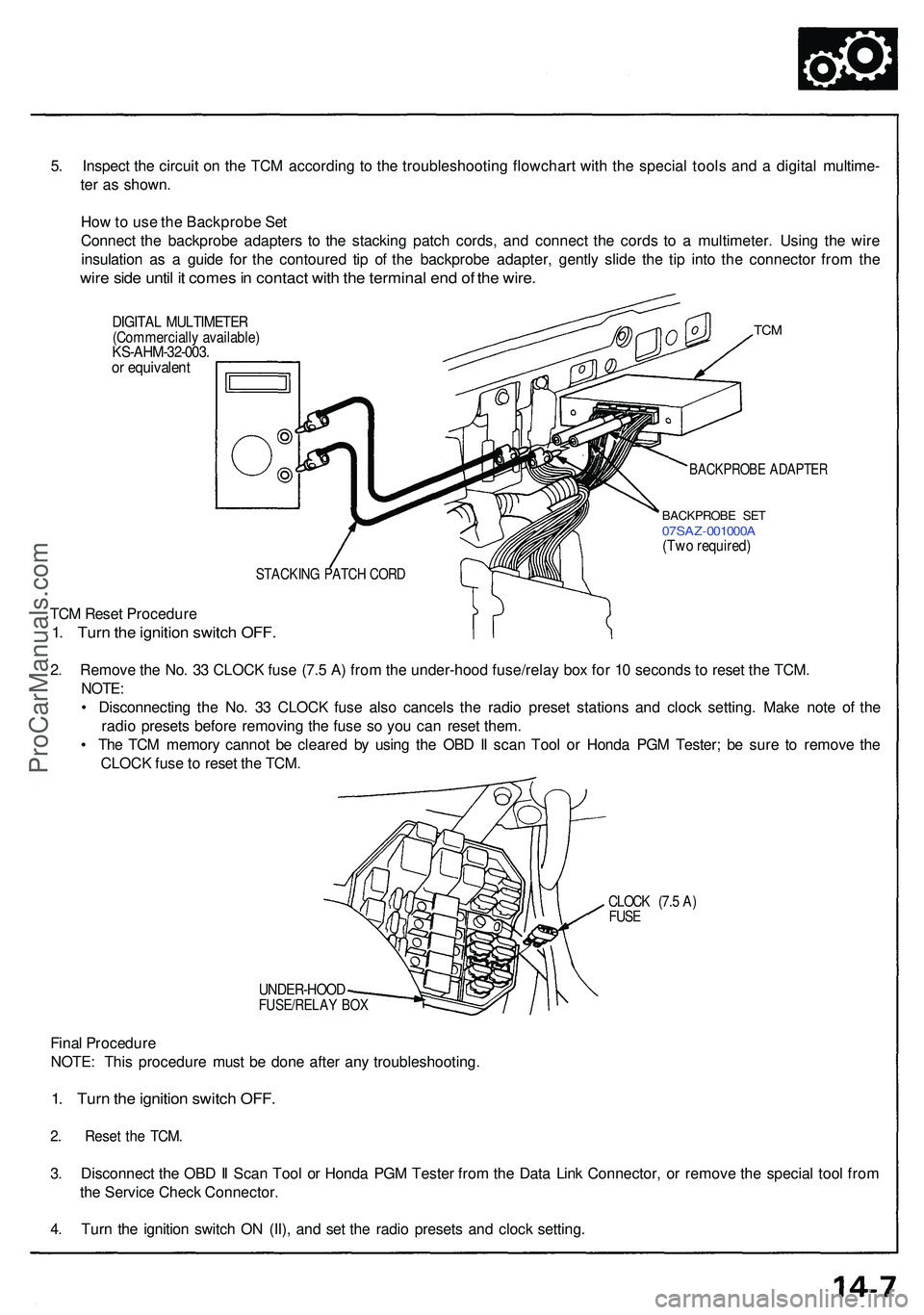
5. Inspec t th e circui t o n th e TC M accordin g t o th e troubleshootin g flowchar t wit h th e specia l tool s an d a digita l multime -
te r a s shown .
Ho w to us e th e Backprob e Se t
Connec t th e backprob e adapter s t o th e stackin g patc h cords , an d connec t th e cord s t o a multimeter . Usin g th e wir e
insulatio n a s a guid e fo r th e contoure d ti p o f th e backprob e adapter , gentl y slid e th e ti p int o th e connecto r fro m th e
wire sid e unti l i t come s in contac t wit h th e termina l en d o f th e wire .
DIGITA L MULTIMETE R(Commerciall y available )KS-AHM-32-003 .or equivalen t
TCM
BACKPROB E ADAPTE R
BACKPROB E SE T07SA Z-001000 A(Two required )
STACKIN G PATC H COR D
TCM Rese t Procedur e
1. Tur n th e ignitio n switc h OFF .
2. Remov e th e No . 3 3 CLOC K fus e (7. 5 A ) fro m th e under-hoo d fuse/rela y bo x fo r 1 0 second s t o rese t th e TCM .
NOTE :
• Disconnectin g th e No . 3 3 CLOC K fus e als o cancel s th e radi o prese t station s an d cloc k setting . Mak e not e o f th e
radi o preset s befor e removin g th e fus e s o yo u ca n rese t them .
• Th e TC M memor y canno t b e cleare d b y usin g th e OB D II sca n Too l o r Hond a PG M Tester ; b e sur e t o remov e th e
CLOC K fus e to rese t th e TCM .
CLOC K (7. 5 A )FUS E
UNDER-HOO DFUSE/RELAY BO X
Fina l Procedur e
NOTE : Thi s procedur e mus t b e don e afte r an y troubleshooting .
1. Tur n th e ignitio n switc h OFF .
2. Rese t th e TCM .
3. Disconnec t th e OB D II Sca n Too l o r Hond a PG M Teste r fro m th e Dat a Lin k Connector , o r remov e th e specia l too l fro m
th e Servic e Chec k Connector .
4 . Tur n th e ignitio n switc h O N (II) , an d se t th e radi o preset s an d cloc k setting .
ProCarManuals.com
Page 130 of 1503
II. Engine Control Module (ECM) Reset Procedure
Either of the following actions, will reset the ECM.
• Using the OBD II scan tool or Honda PGM Tester to clear the ECM's memory.
NOTE: See the OBD II scan tool or Honda PGM Tester user's manuals for specific operating instructions.
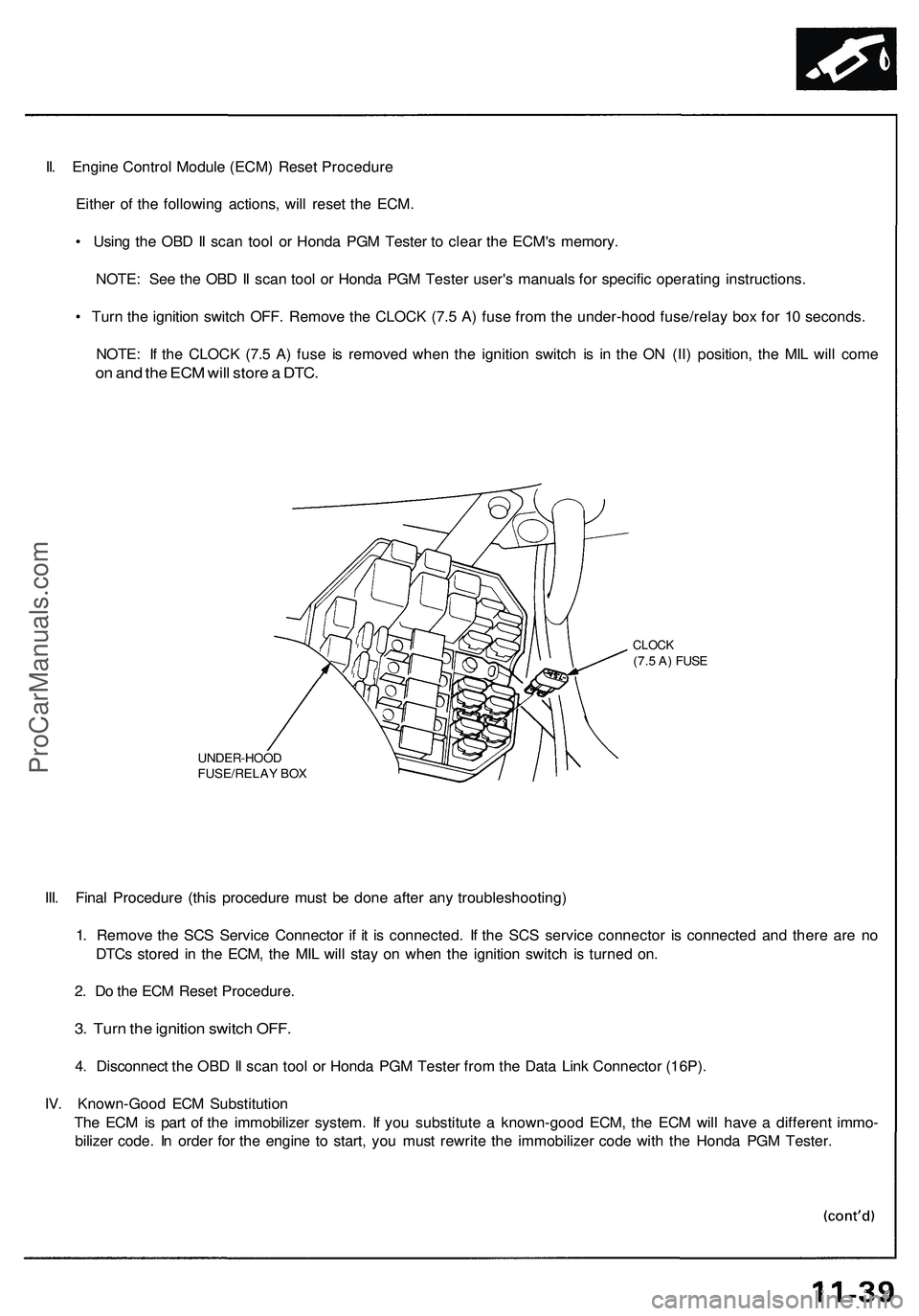
• Turn the ignition switch OFF. Remove the CLOCK (7.5 A) fuse from the under-hood fuse/relay box for 10 seconds.
NOTE: If the CLOCK (7.5 A) fuse is removed when the ignition switch is in the ON (II) position, the MIL will come
on and the ECM will store a DTC.
UNDER-HOOD
FUSE/RELAY BOX
CLOCK
(7.5 A) FUSE
III. Final Procedure (this procedure must be done after any troubleshooting)
1. Remove the SCS Service Connector if it is connected. If the SCS service connector is connected and there are no
DTCs stored in the ECM, the MIL will stay on when the ignition switch is turned on.
2. Do the ECM Reset Procedure.
3. Turn the ignition switch OFF.
4. Disconnect the OBD II scan tool or Honda PGM Tester from the Data Link Connector (16P).
IV. Known-Good ECM Substitution
The ECM is part of the immobilizer system. If you substitute a known-good ECM, the ECM will have a different immo-
bilizer code. In order for the engine to start, you must rewrite the immobilizer code with the Honda PGM Tester.ProCarManuals.com
Page 141 of 1503
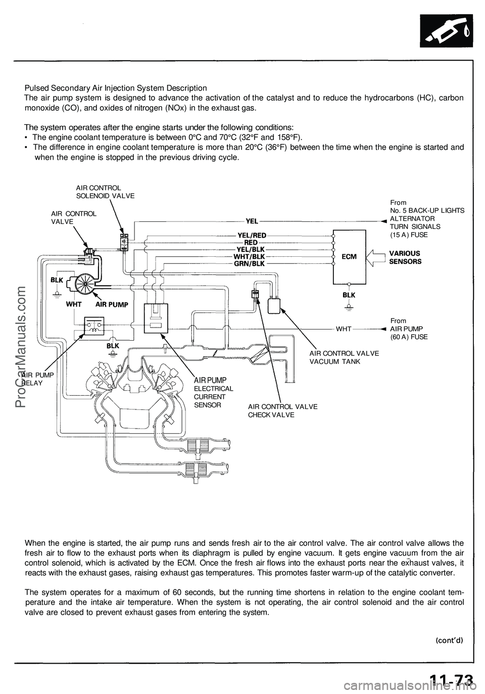
Pulsed Secondary Air Injection System Description
The air pump system is designed to advance the activation of the catalyst and to reduce the hydrocarbons (HC), carbon
monoxide (CO), and oxides of nitrogen (NOx) in the exhaust gas.
The system operates after the engine starts under the following conditions:
• The engine coolant temperature is between 0°C and 70°C (32°F and 158°F).
• The difference in engine coolant temperature is more than 20°C (36°F) between the time when the engine is started and
when the engine is stopped in the previous driving cycle.
AIR CONTROL
SOLENOID VALVE
AIR CONTROL
VALVE
WHT
AIR PUMP
RELAY
From
No. 5 BACK-UP LIGHTS
ALTERNATOR
TURN SIGNALS
(15 A) FUSE
From
AIR PUMP
(60 A) FUSE
AIR CONTROL VALVE
VACUUM TANK
AIR CONTROL VALVE
CHECK VALVE
When the engine is started, the air pump runs and sends fresh air to the air control valve. The air control valve allows the
fresh air to flow to the exhaust ports when its diaphragm is pulled by engine vacuum. It gets engine vacuum from the air
control solenoid, which is activated by the ECM. Once the fresh air flows into the exhaust ports near the exhaust valves, it
reacts with the exhaust gases, raising exhaust gas temperatures. This promotes faster warm-up of the catalytic converter.
The system operates for a maximum of 60 seconds, but the running time shortens in relation to the engine coolant tem-
perature and the intake air temperature. When the system is not operating, the air control solenoid and the air control
valve are closed to prevent exhaust gases from entering the system.
AIR PUMP
ELECTRICAL
CURRENT
SENSORProCarManuals.com
Page 159 of 1503
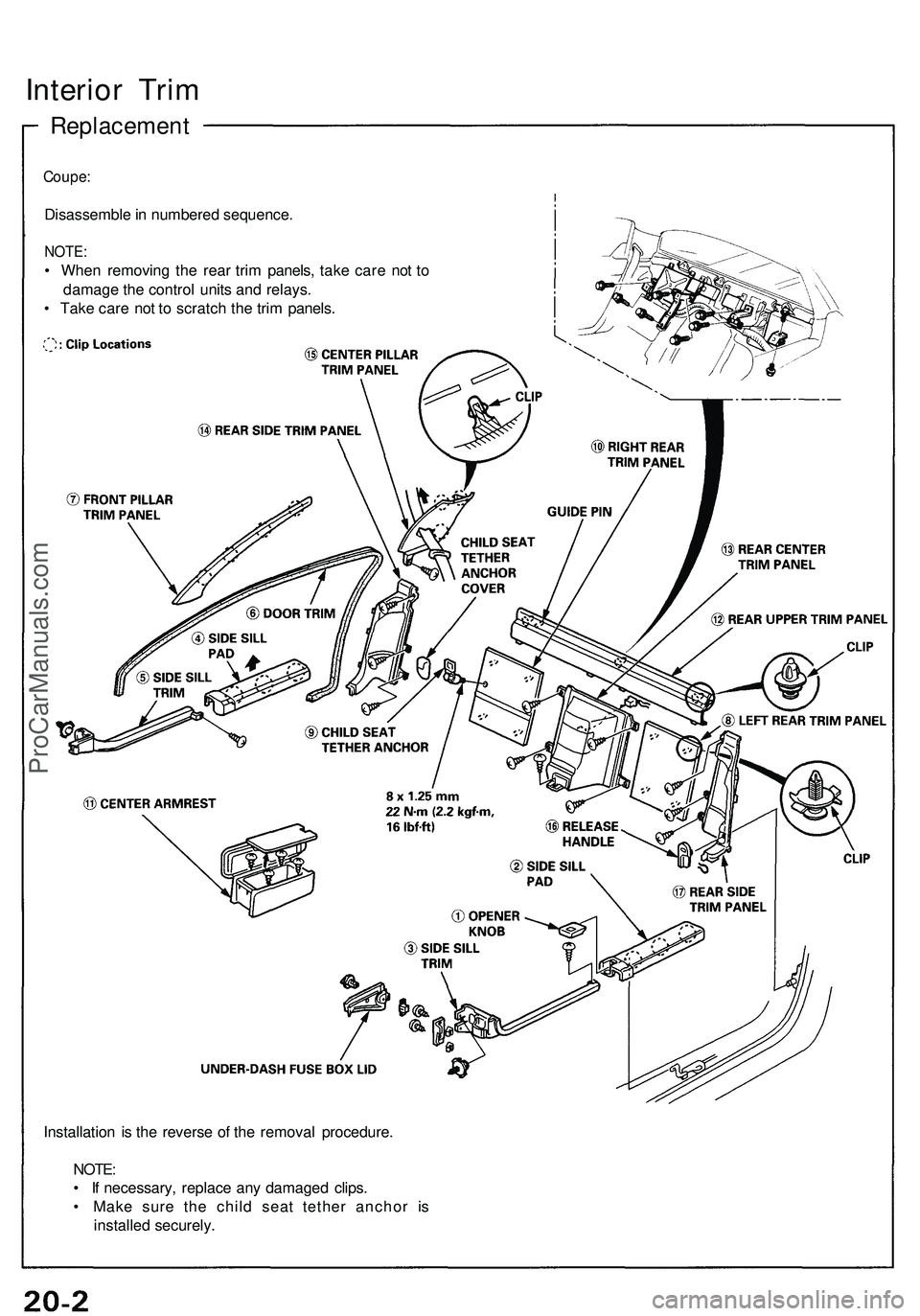
Interior Tri m
Replacemen t
Coupe:
Disassembl e in numbere d sequence .
NOTE:
• Whe n removin g th e rea r tri m panels , tak e car e no t t o
damag e th e contro l unit s an d relays .
• Tak e car e no t t o scratc h th e tri m panels .
Installatio n i s th e revers e o f th e remova l procedure .
NOTE :
• I f necessary , replac e an y damage d clips .
• Mak e sur e th e chil d sea t tethe r ancho r i s
installe d securely .
ProCarManuals.com
Page 161 of 1503
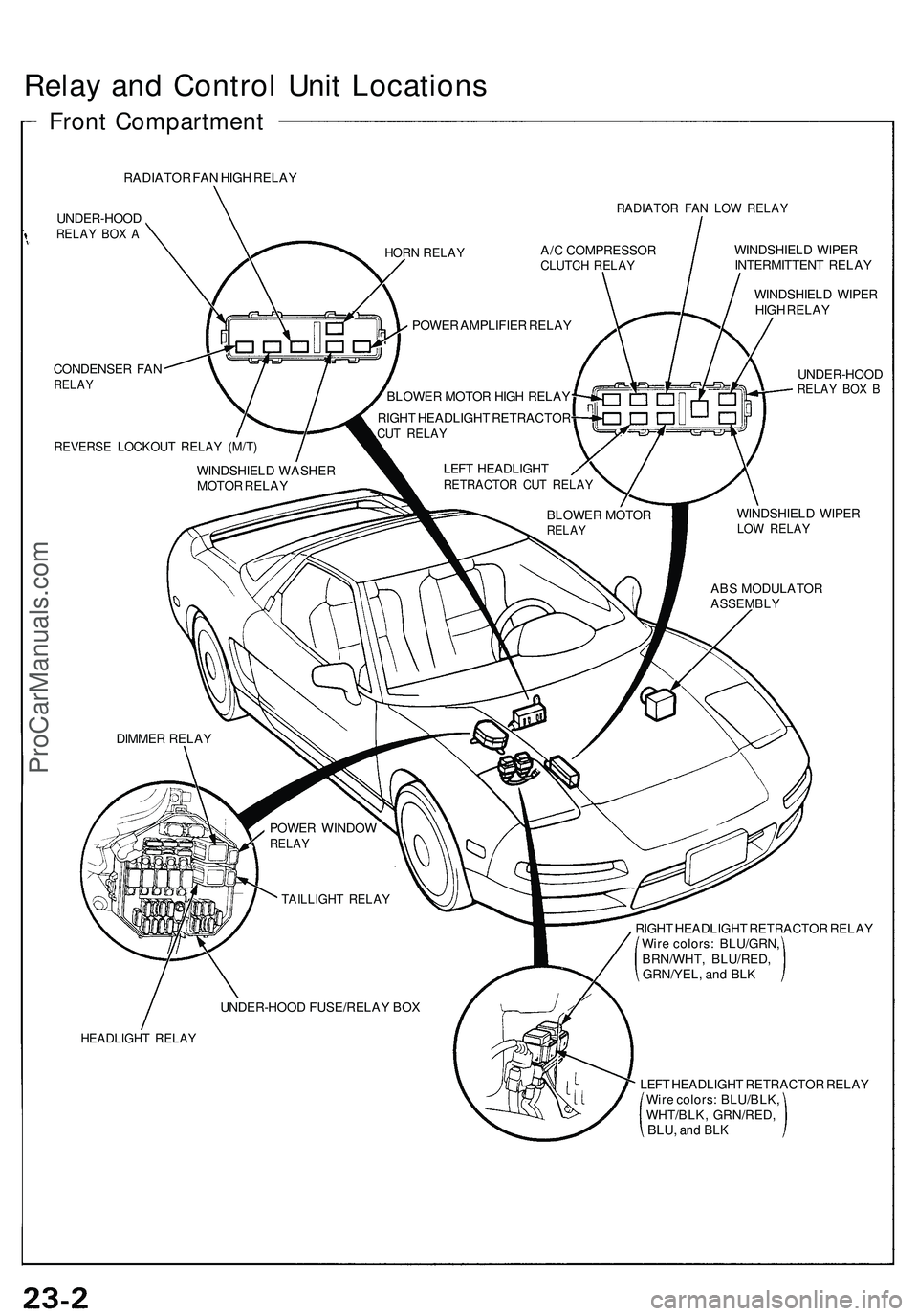
Relay an d Contro l Uni t Location s
Front Compartmen t
RADIATOR FA N HIG H RELA Y
UNDER-HOO D
RELAY BO X A
RADIATO R FA N LO W RELA Y
CONDENSE R FA NRELA Y
REVERS E LOCKOU T RELA Y (M/T )
WINDSHIEL D WIPE R
INTERMITTEN T RELA Y
WINDSHIEL D WIPE R
HIG H RELA Y
UNDER-HOO D
RELAY BO X B
WINDSHIEL D WIPE RLOW RELA Y
RIGHT HEADLIGH T RETRACTO R RELA Y
Wir e colors : BLU/GRN ,
BRN/WHT , BLU/RED ,
GRN/YEL , an d BL K
HEADLIGH T RELA Y
LEFT HEADLIGH T RETRACTO R RELA Y
Wir e colors : BLU/BLK ,
WHT/BLK , GRN/RED ,
BLU, and BL K
HOR N RELA YA/C COMPRESSO RCLUTCH RELA Y
POWER AMPLIFIE R RELA Y
BLOWE R MOTO R HIG H RELA Y
RIGH T HEADLIGH T RETRACTO R
CUT RELA Y
LEFT HEADLIGH TRETRACTO R CU T RELA Y
BLOWE R MOTO RRELAY
ABS MODULATO RASSEMBLY
WINDSHIEL D WASHE R
MOTO R RELA Y
DIMME R RELA Y
POWER WINDO W
RELAY
TAILLIGH T RELA Y
UNDER-HOO D FUSE/RELA Y BO X
ProCarManuals.com
Page 162 of 1503
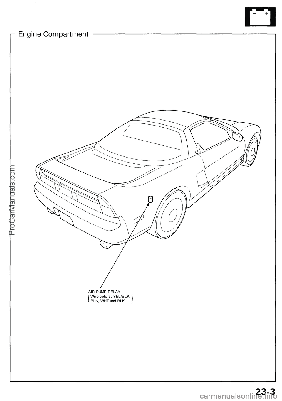
Engine Compartment
AIR PUMP RELAY
Wire colors: YEL/BLK,
BLK,
WHT and BLKProCarManuals.com
Page 193 of 1503
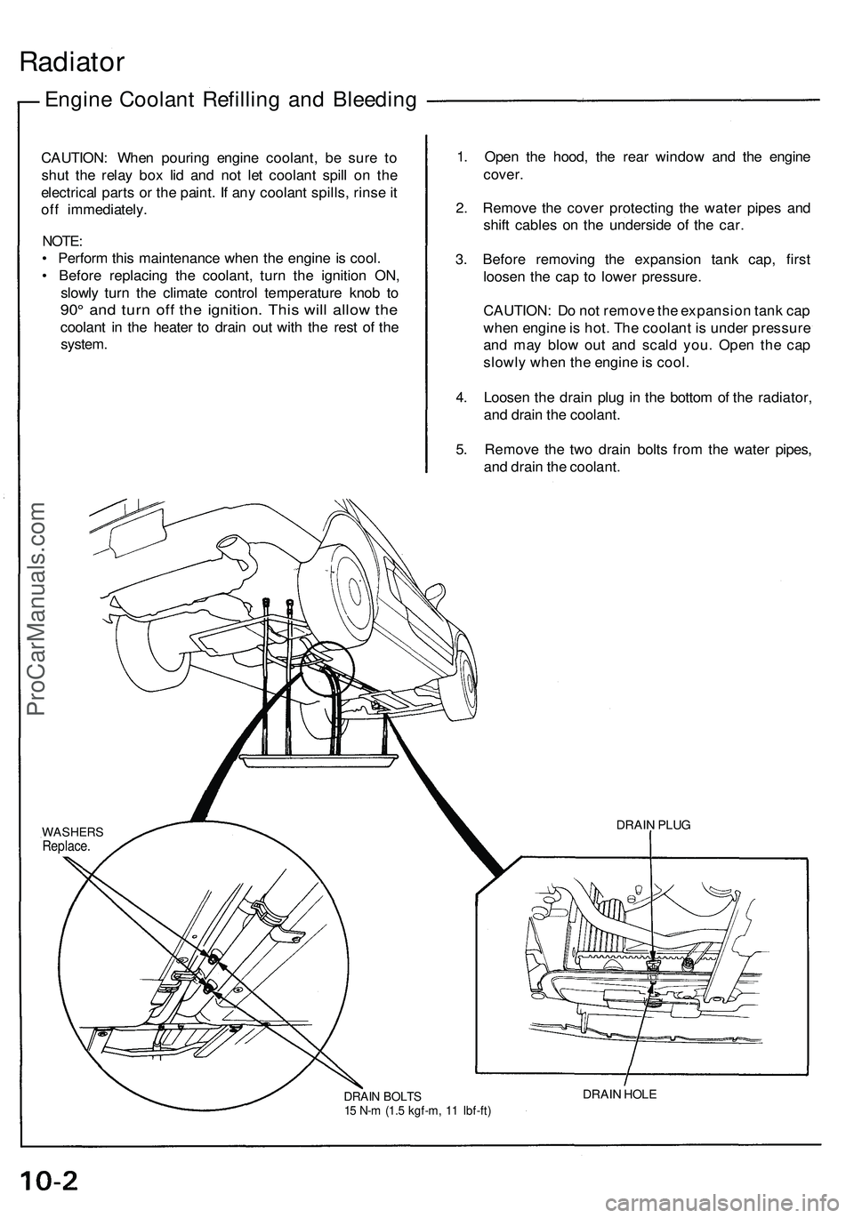
Radiator
Engine Coolant Refilling and Bleeding
CAUTION: When pouring engine coolant, be sure to
shut the relay box lid and not let coolant spill on the
electrical parts or the paint. If any coolant spills, rinse it
off immediately.
NOTE:
• Perform this maintenance when the engine is cool.
• Before replacing the coolant, turn the ignition ON,
slowly turn the climate control temperature knob to
90° and turn off the ignition. This will allow the
coolant in the heater to drain out with the rest of the
system.
1. Open the hood, the rear window and the engine
cover.
2. Remove the cover protecting the water pipes and
shift cables on the underside of the car.
3. Before removing the expansion tank cap, first
loosen the cap to lower pressure.
CAUTION: Do not remove the expansion tank cap
when engine is hot. The coolant is under pressure
and may blow out and scald you. Open the cap
slowly when the engine is cool.
4. Loosen the drain plug in the bottom of the radiator,
and drain the coolant.
5. Remove the two drain bolts from the water pipes,
and drain the coolant.
DRAIN BOLTS
15 N-m (1.5 kgf-m, 11 Ibf-ft)
DRAIN HOLE
DRAIN PLUG
WASHERS
Replace.ProCarManuals.com
Page 262 of 1503
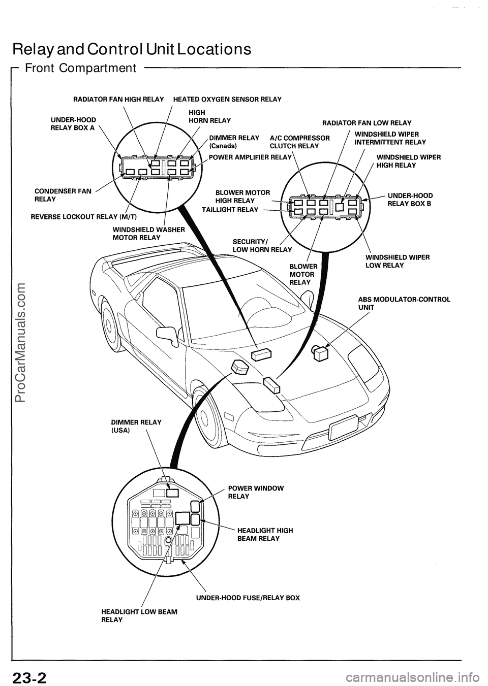
Relay an d Contro l Uni t Location s
Front Compartmen t
ProCarManuals.com
Page 271 of 1503
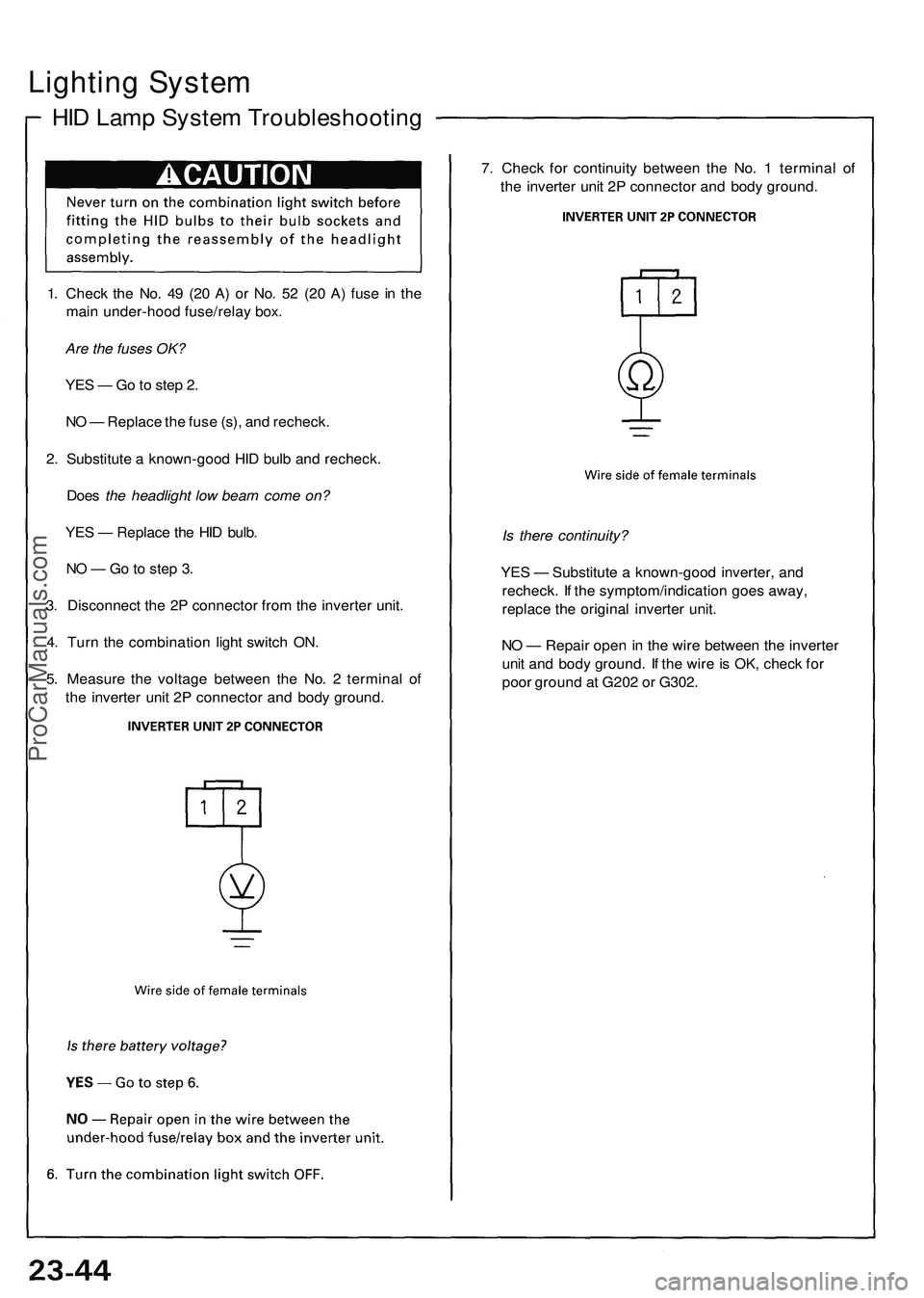
Lighting System
HID Lamp System Troubleshooting
1. Check the No. 49 (20 A) or No. 52 (20 A) fuse in the
main under-hood fuse/relay box.
Are the fuses OK?
YES — Go to step 2.
NO — Replace the fuse (s), and recheck.
2. Substitute a known-good HID bulb and recheck.
Does the headlight low beam come on?
YES — Replace the HID bulb.
NO — Go to step 3.
3. Disconnect the 2P connector from the inverter unit.
4. Turn the combination light switch ON.
5. Measure the voltage between the No. 2 terminal of
the inverter unit 2P connector and body ground.
7. Check for continuity between the No. 1 terminal of
the inverter unit 2P connector and body ground.
Is there continuity?
YES — Substitute a known-good inverter, and
recheck. If the symptom/indication goes away,
replace the original inverter unit.
NO — Repair open in the wire between the inverter
unit and body ground. If the wire is OK, check for
poor ground at G202 or G302.ProCarManuals.com
Page 272 of 1503
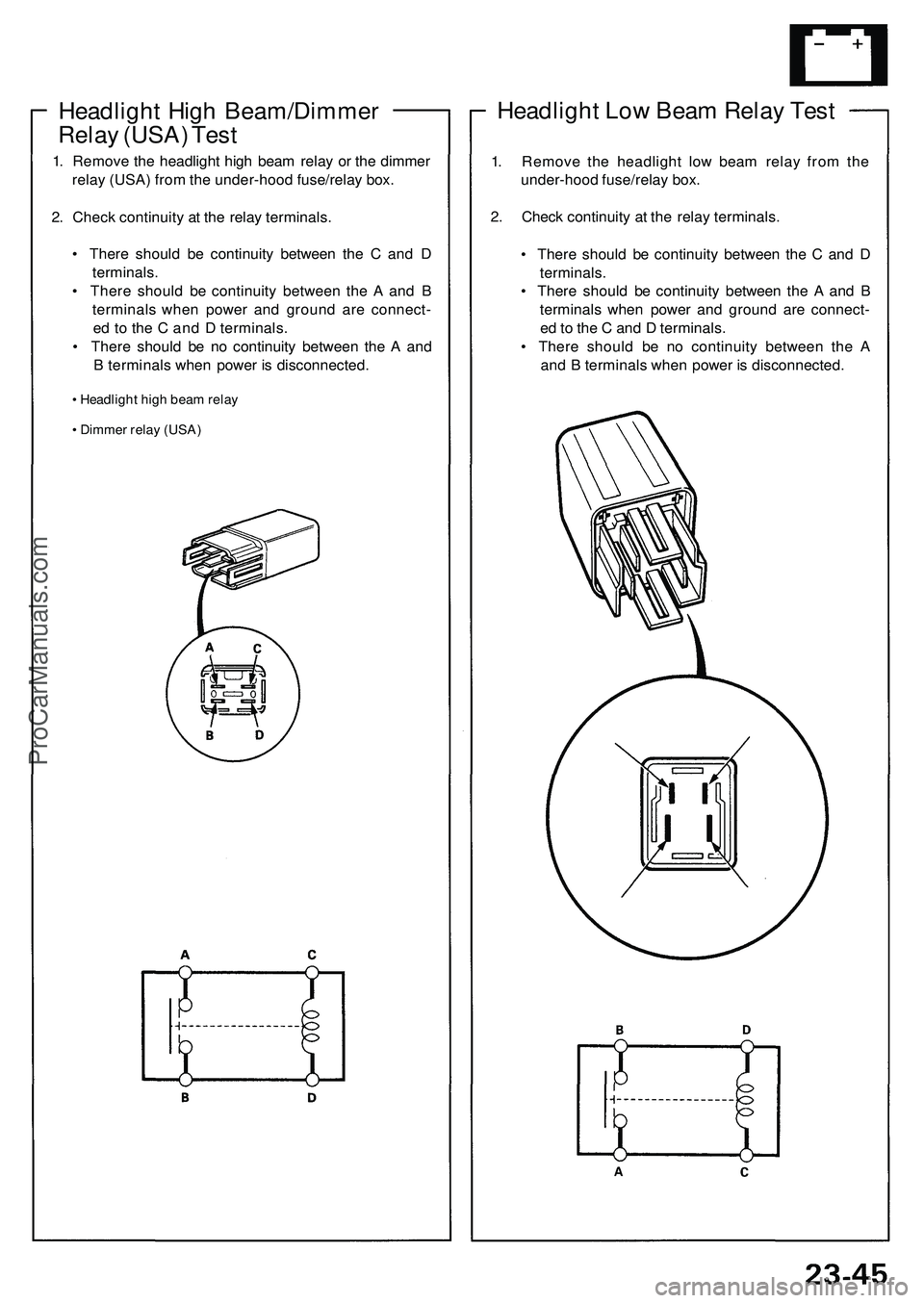
Headlight Low Beam Relay Test
1. Remove the headlight low beam relay from the
under-hood fuse/relay box.
2. Check continuity at the relay terminals.
• There should be continuity between the C and D
terminals.
• There should be continuity between the A and B
terminals when power and ground are connect-
ed to the C and D terminals.
• There should be no continuity between the A
and B terminals when power is disconnected.
Headlight High Beam/Dimmer
Relay (USA) Test
1. Remove the headlight high beam relay or the dimmer
relay (USA) from the under-hood fuse/relay box.
2. Check continuity at the relay terminals.
• There should be continuity between the C and D
terminals.
• There should be continuity between the A and B
terminals when power and ground are connect-
ed to the C and D terminals.
• There should be no continuity between the A and
B terminals when power is disconnected.
• Headlight high beam relay
• Dimmer relay (USA)ProCarManuals.com