relay ACURA NSX 1997 Service User Guide
[x] Cancel search | Manufacturer: ACURA, Model Year: 1997, Model line: NSX, Model: ACURA NSX 1997Pages: 1503, PDF Size: 57.08 MB
Page 273 of 1503
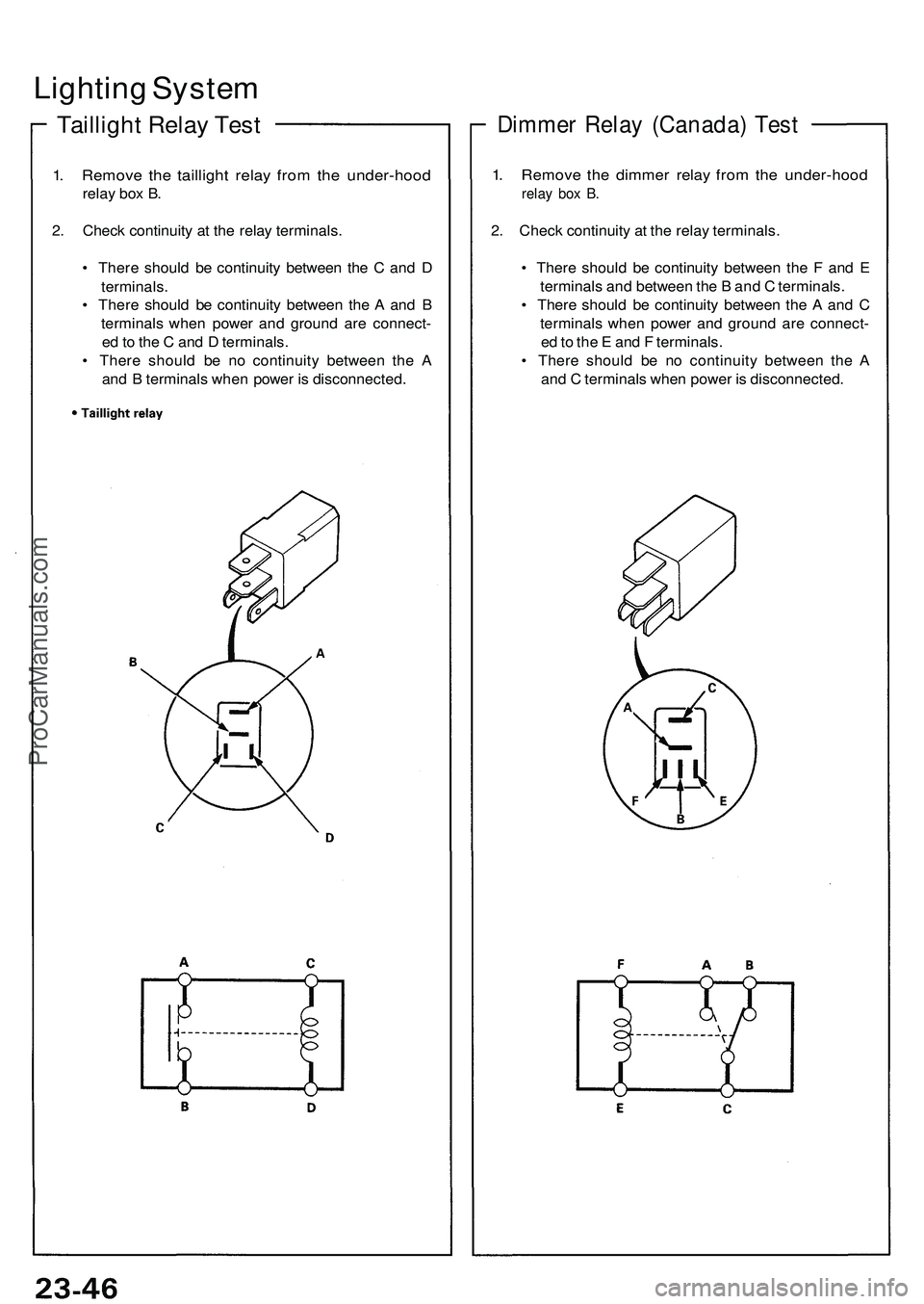
Lighting Syste m
Tailligh t Rela y Tes t
1. Remov e th e tailligh t rela y fro m th e under-hoo d
relay bo x B .
2 . Chec k continuit y a t th e rela y terminals .
• Ther e shoul d b e continuit y betwee n th e C an d D
terminals .
• Ther e shoul d b e continuit y betwee n th e A an d B
terminal s whe n powe r an d groun d ar e connect -
e d to th e C an d D terminals .
• Ther e shoul d b e n o continuit y betwee n th e A
an d B terminal s whe n powe r i s disconnected .
Dimmer Rela y (Canada ) Tes t
1. Remov e th e dimme r rela y fro m th e under-hoo d
relay bo x B .
2. Chec k continuit y a t th e rela y terminals .
• Ther e shoul d b e continuit y betwee n th e F an d E
terminal s an d betwee n th e B an d C terminals .
• Ther e shoul d b e continuit y betwee n th e A an d C
terminal s whe n powe r an d groun d ar e connect -
e d to th e E an d F terminals .
• Ther e shoul d b e n o continuit y betwee n th e A
an d C terminal s whe n powe r i s disconnected .
ProCarManuals.com
Page 277 of 1503
Description
Security Alar m System :
Th e securit y alar m syste m is a n anti-thef t alar m system . I f someon e trie s t o ope n th e trunk , hoo d o r eithe r doo r withou t
th e ignitio n key , o r i f th e roo f i s no t full y latched , th e securit y contro l uni t sense s a signa l fro m th e sensor s an d activate s
relay s t o flas h th e headlight s an d soun d th e hor n fo r abou t tw o minutes .
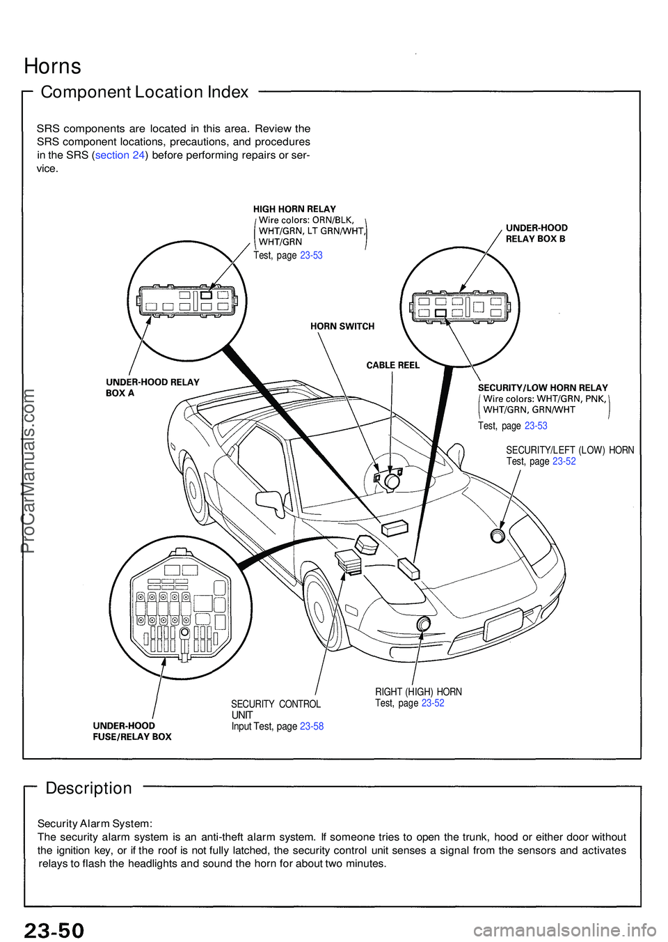
SECURIT Y CONTRO LUNITInpu t Test , pag e 23-5 8
RIGH T (HIGH ) HOR N
Test , pag e 23-5 2
Horn s
Componen t Locatio n Inde x
SRS component s ar e locate d i n thi s area . Revie w th e
SR S componen t locations , precautions , an d procedure s
i n th e SR S (sectio n 24 ) befor e performin g repair s o r ser -
vice .
Test , pag e 23-5 3
Test, pag e 23-5 3
SECURITY/LEF T (LOW ) HOR N
Test , pag e 23-5 2
ProCarManuals.com
Page 343 of 1503
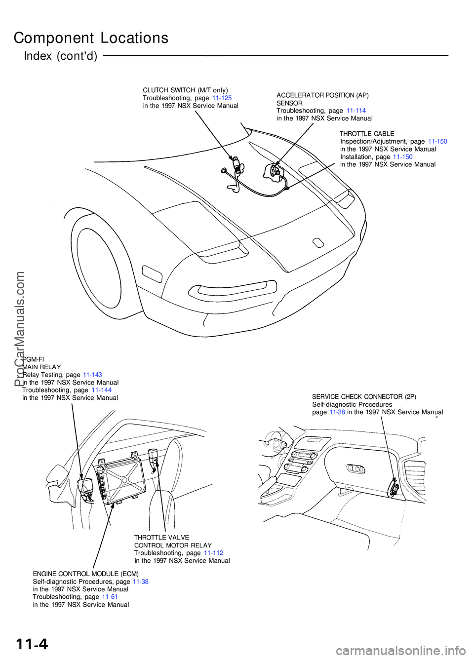
Component Location s
Index (cont'd )
CLUTCH SWITC H (M/ T only )Troubleshooting , pag e 11-12 5in th e 199 7 NS X Servic e Manua l
ACCELERATO R POSITIO N (AP )SENSO RTroubleshooting , pag e 11-11 4in th e 199 7 NS X Servic e Manua l
THROTTL E CABL EInspection/Adjustment , pag e 11-15 0in th e 199 7 NS X Servic e Manua lInstallation , pag e 11-15 0in th e 199 7 NS X Servic e Manua l
PGM-FIMAIN RELA YRelay Testing , pag e 11-14 3in th e 199 7 NS X Servic e Manua lTroubleshooting , pag e 11-14 4in th e 199 7 NS X Servic e Manua lSERVIC E CHEC K CONNECTO R (2P )Self-diagnosti c Procedure spage 11-3 8 in th e 199 7 NS X Servic e Manua l
THROTTL E VALV ECONTRO L MOTO R RELA YTroubleshooting , pag e 11-11 2in th e 199 7 NS X Servic e Manua l
ENGINE CONTRO L MODUL E (ECM )Self-diagnosti c Procedures , pag e 11-3 8in th e 199 7 NS X Servic e Manua lTroubleshooting , pag e 11-6 1in th e 199 7 NS X Servic e Manua l
ProCarManuals.com
Page 370 of 1503
3-15
T
ITEMMETRICENGLISH
ELECTRICALBattery
Starter
Alternator
Fuses
In the under-dash fuse box
In the under-hood fuse/relay box
In the engine compartment
fuse/relay box
Headlights, high, low
Front turn signal lights
Front parking lights
Rear turn signal lights
Brake/Taillights
Taillights
Front side marker lights
Rear side marker lights
Back-up lights
License plate lights
Gauge lights
Indicator lights
Glove box and fuse lights
Ceiling lights
Trunk lights
Door courtesy lights
Footwell light
Illumination and indicator lights
High mount brake light12 V – 52AH/5HR
12 V – 55AH/5HR
12 V – 1.4 kW
12 V – 120 A
7.5 A, 10 A, 15 A
7.5 A, 10 A, 15 A, 20 A, 30 A, 40 A, 50 A
10 A, 20 A, 30 A, 40 A, 120 A
12 V – 65 W/35 W (HID)
12 V – 45 CP
12 V – 5 W
12 V – 45 CP
12 V – 32/2 CP
12 V – 2 CP
12 V – 3 CP
12 V – 3 CP
12 V – 32 CP
12 V – 8 W
12 V – 3.0 W, 1.4 W
12 V – 1.4 W, 1.96 W
12 V – 3.4 W
12 V – 8 W
12 V – 3.4 W
12 V – 3.4 W
12 V – 5 W
12 V – 1.4 W, 0.84 W
12 V – 0.91 W, LED
LED
TIRE
M/T
A/T
BRAKE SYSTEM
Front: 215/40 R17 83Y Rear: 255/40 R17 94Y165/80 D 16 (Folding spare tire)
Power assisted self-adjusting
ventilated disc
58.0/38.8 cm
28.99/6.01 sq in
Mechanical expanding, rear two wheel
brakes
WHEEL
ALIGNMENTCamber Front
Rear
Caster
Toe Front
Rear–0 °20 ’
–1 °30 ’
8 °
Out 3.5 mm Out 0.14 in
In 4.0 mm In 3/16 in
NOTES
Size
Type, front and rear
Pad and lining surface area: front/rear
Parking brake type
*04-NSX (61SW004)SEC03(01-16) 9/22/04 1:49 PM Page 3-15
ProCarManuals.com
Page 521 of 1503
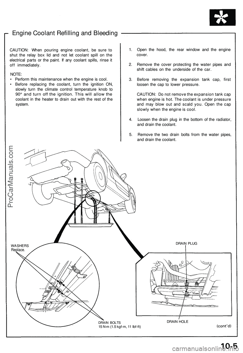
Engine Coolant Refilling and Bleeding
CAUTION: When pouring engine coolant, be sure to
shut the relay box lid and not let coolant spill on the
electrical parts or the paint. If any coolant spills, rinse it
off immediately.
NOTE:
• Perform this maintenance when the engine is cool.
• Before replacing the coolant, turn the ignition ON,
slowly turn the climate control temperature knob to
90° and turn off the ignition. This will allow the
coolant in the heater to drain out with the rest of the
system.
1. Open the hood, the rear window and the engine
cover.
2. Remove the cover protecting the water pipes and
shift cables on the underside of the car.
3. Before removing the expansion tank cap, first
loosen the cap to lower pressure.
CAUTION: Do not remove the expansion tank cap
when engine is hot. The coolant is under pressure
and may blow out and scald you. Open the cap
slowly when the engine is cool.
4. Loosen the drain plug in the bottom of the radiator,
and drain the coolant.
5. Remove the two drain bolts from the water pipes,
and drain the coolant.
WASHERS
Replace.
DRAIN BOLTS
15 N-m (1.5 kgf-m, 11 Ibf-ft)
DRAIN HOLE
DRAIN PLUGProCarManuals.com
Page 560 of 1503
![ACURA NSX 1997 Service User Guide
System Description
System Connectors [Front Compartment and Under-dash] (cont'd)
FLOOR
WIRE
HARNESS
UNDER-HOOD
FUSE/RELAY
BOX
FRONT
COMPARTMENT
WIRE
HARNESS
UNDER-DASH
FUSE
BOX
SID ACURA NSX 1997 Service User Guide
System Description
System Connectors [Front Compartment and Under-dash] (cont'd)
FLOOR
WIRE
HARNESS
UNDER-HOOD
FUSE/RELAY
BOX
FRONT
COMPARTMENT
WIRE
HARNESS
UNDER-DASH
FUSE
BOX
SID](/img/32/56989/w960_56989-559.png)
System Description
System Connectors [Front Compartment and Under-dash] (cont'd)
FLOOR
WIRE
HARNESS
UNDER-HOOD
FUSE/RELAY
BOX
FRONT
COMPARTMENT
WIRE
HARNESS
UNDER-DASH
FUSE
BOX
SIDE
WIRE
HARNESSProCarManuals.com
Page 562 of 1503
![ACURA NSX 1997 Service User Guide
System Description
System Connectors [Front Compartment and Under-dash] (cont'd)
UNDER-HOOD
FUSE/RELAY
BOX
SUB RELAY
BOX A
FRONT
COMPARTMENT
WIRE
HARNESS
UNDER-DASH
FUSE
BOX
SIDE
W ACURA NSX 1997 Service User Guide
System Description
System Connectors [Front Compartment and Under-dash] (cont'd)
UNDER-HOOD
FUSE/RELAY
BOX
SUB RELAY
BOX A
FRONT
COMPARTMENT
WIRE
HARNESS
UNDER-DASH
FUSE
BOX
SIDE
W](/img/32/56989/w960_56989-561.png)
System Description
System Connectors [Front Compartment and Under-dash] (cont'd)
UNDER-HOOD
FUSE/RELAY
BOX
SUB RELAY
BOX A
FRONT
COMPARTMENT
WIRE
HARNESS
UNDER-DASH
FUSE
BOX
SIDE
WIRE
HARNESS
FLOOR
WIRE
HARNESSProCarManuals.com
Page 565 of 1503
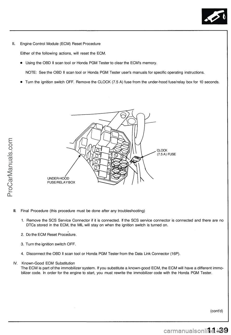
Engine Control Module (ECM) Reset Procedure
Either of the following actions, will reset the ECM.
Using the OBD II scan tool or Honda PGM Tester to clear the ECM's memory.
NOTE: See the OBD II scan tool or Honda PGM Tester user's manuals for specific operating instructions.
Turn the ignition switch OFF. Remove the CLOCK (7.5 A) fuse from the under-hood fuse/relay box for 10 seconds.
UNDER-HOOD
FUSE/RELAY BOX
CLOCK
(7.5 A) FUSE
III. Final Procedure (this procedure must be done after any troubleshooting)
1. Remove the SCS Service Connector if it is connected. If the SCS service connector is connected and there are no
DTCs stored in the ECM, the MIL will stay on when the ignition switch is turned on.
2. Do the ECM Reset Procedure.
3. Turn the ignition switch OFF.
4. Disconnect the OBD II scan tool or Honda PGM Tester from the Data Link Connector (16P).
IV. Known-Good ECM Substitution
The ECM is part of the immobilizer system. If you substitute a known-good ECM, the ECM will have a different immo-
bilizer code. In order for the engine to start, you must rewrite the immobilizer code with the Honda PGM Tester.
(cont'd)ProCarManuals.com
Page 572 of 1503
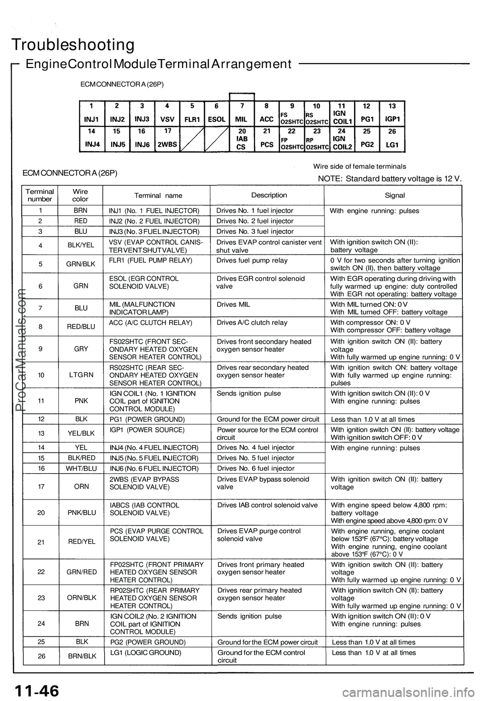
Troubleshooting
Engine Control Module Terminal Arrangement
ECM CONNECTOR A (26P)
ECM CONNECTOR A (26P)
Wire side of female terminals
NOTE: Standard battery voltage is 12 V.
Terminal
number
1
2
3
4
5
6
7
8
9
10
11
12
13
14
15
16
17
20
21
22
23
24
25
26
Wire
color
BRN
RED
BLU
BLK/YEL
GRN/BLK
GRN
BLU
RED/BLU
GRY
LTGRN
PNK
BLK
YEL/BLK
YEL
BLK/RED
WHT/BLU
ORN
PNK/BLU
RED/YEL
GRN/RED
ORN/BLK
BRN
BLK
BRN/BLK
Terminal name
INJ1 (No. 1 FUEL INJECTOR)
INJ2 (No. 2 FUEL INJECTOR)
INJ3 (No. 3 FUEL INJECTOR)
VSV (EVAP CONTROL CANIS-
TER VENT SHUT VALVE)
FLR1 (FUEL PUMP RELAY)
ESOL (EGR CONTROL
SOLENOID VALVE)
MIL (MALFUNCTION
INDICATOR LAMP)
ACC (A/C CLUTCH RELAY)
FS02SHTC (FRONT SEC-
ONDARY HEATED OXYGEN
SENSOR HEATER CONTROL)
RS02SHTC (REAR SEC-
ONDARY HEATED OXYGEN
SENSOR HEATER CONTROL)
IGN COIL1 (No. 1 IGNITION
COIL part of IGNITION
CONTROL MODULE)
PG1 (POWER GROUND)
IGP1 (POWER SOURCE)
INJ4 (No. 4 FUEL INJECTOR)
INJ5 (No. 5 FUEL INJECTOR)
INJ6 (No. 6 FUEL INJECTOR)
2WBS (EVAP BYPASS
SOLENOID VALVE)
IABCS (IAB CONTROL
SOLENOID VALVE)
PCS (EVAP PURGE CONTROL
SOLENOID VALVE)
FP02SHTC (FRONT PRIMARY
HEATED OXYGEN SENSOR
HEATER CONTROL)
RP02SHTC (REAR PRIMARY
HEATED OXYGEN SENSOR
HEATER CONTROL)
IGN COIL2 (No. 2 IGNITION
COIL part of IGNITION
CONTROL MODULE)
PG2 (POWER GROUND)
LG1 (LOGIC GROUND)
Description
Drives No. 1 fuel injector
Drives No. 2 fuel injector
Drives No. 3 fuel injector
Drives EVAP control canister vent
shut valve
Drives fuel pump relay
Drives EGR control solenoid
valve
Drives MIL
Drives A/C clutch relay
Drives front secondary heated
oxygen sensor heater
Drives rear secondary heated
oxygen sensor heater
Sends ignition pulse
Ground for the ECM power circuit
Power source for the ECM control
circuit
Drives No. 4 fuel injector
Drives No. 5 fuel injector
Drives No. 6 fuel injector
Drives EVAP bypass solenoid
valve
Drives IAB control solenoid valve
Drives EVAP purge control
solenoid valve
Drives front primary heated
oxygen sensor heater
Drives rear primary heated
oxygen sensor heater
Sends ignition pulse
Ground for the ECM power circuit
Ground for the ECM control
circuit
Signal
With engine running: pulses
With ignition switch ON (II):
battery voltage
0 V for two seconds after turning ignition
switch ON (II), then battery voltage
With EGR operating during driving with
fully warmed up engine: duty controlled
With EGR not operating: battery voltage
With MIL turned ON: 0V
With MIL turned OFF: battery voltage
With compressor ON: 0 V
With compressor OFF: battery voltage
With ignition switch ON (II): battery
voltage
With fully warmed up engine running: 0 V
With ignition switch ON: battery voltage
With fully warmed up engine running:
pulses
With ignition switch ON (II): 0 V
With engine running: pulses
Less than 1.0 V at all times
With ignition switch ON (II): battery voltage
With ignition switch OFF: 0 V
With engine running: pulses
With ignition switch ON (II): battery
voltage
With engine speed below 4,800 rpm:
battery voltage
With engine speed above 4,800 rpm: 0 V
With engine running, engine coolant
below 153°F (67°C): battery voltage
With engine running, engine coolant
above 153°F (67°C): 0 V
With ignition switch ON (II): battery
voltage
With fully warmed up engine running: 0 V
With ignition switch ON (II): battery
voltage
With fully warmed up engine running: 0 V
With ignition switch ON (II): 0 V
With engine running: pulses
Less than 1.0 V at all times
Less than 1.0 V at all timesProCarManuals.com
Page 576 of 1503
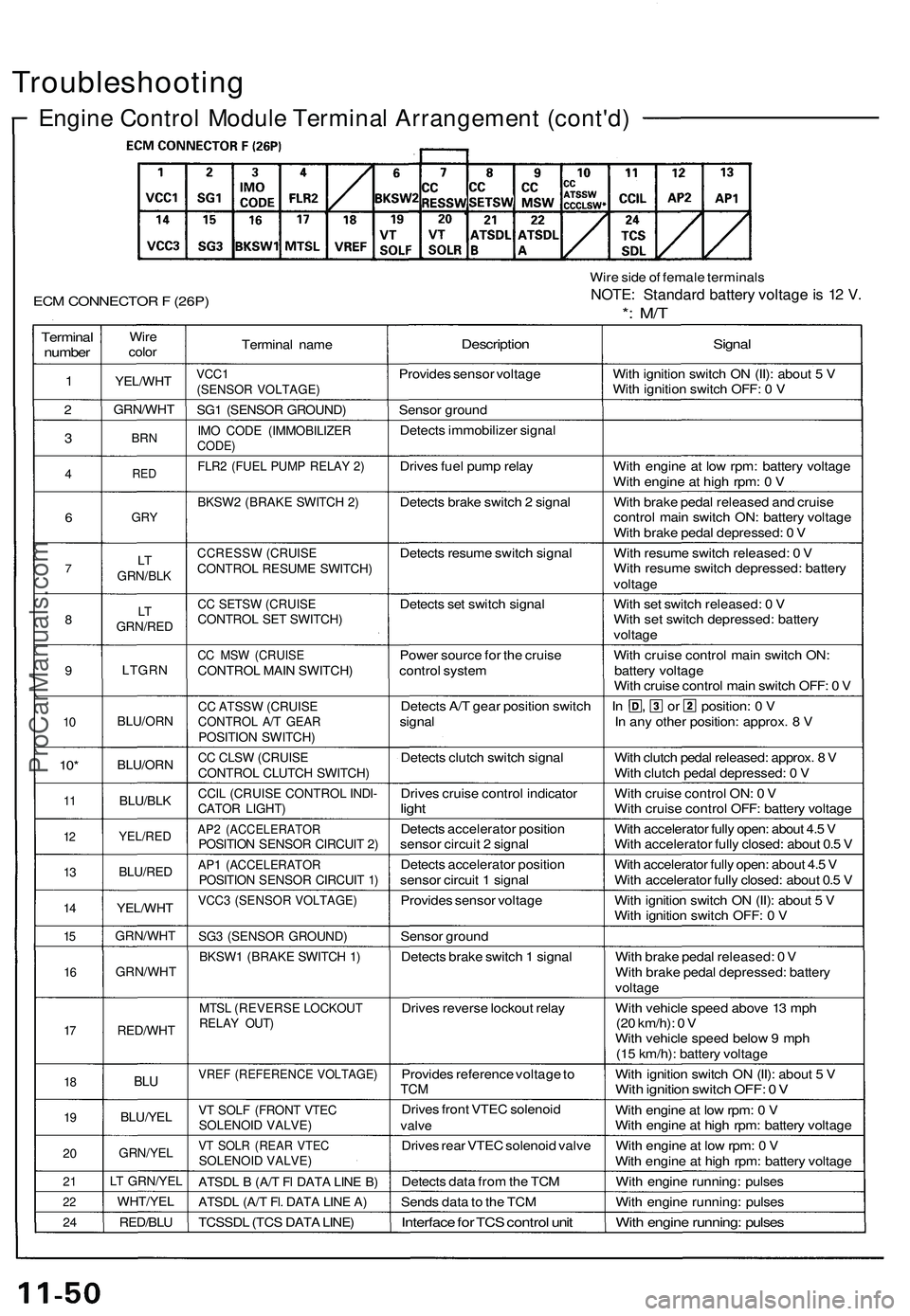
Troubleshooting
Engine Control Module Terminal Arrangement (cont'd)
ECM CONNECTOR F (26P)
Wire side of female terminals
NOTE: Standard battery voltage is 12 V.
*: M/T
Terminal
number
1
2
3
4
6
7
8
9
10
10*
11
12
13
14
15
16
17
18
19
20
21
22
24
Wire
color
YEL/WHT
GRN/WHT
BRN
RED
GRY
LT
GRN/BLK
LT
GRN/RED
LTGRN
BLU/ORN
BLU/ORN
BLU/BLK
YEL/RED
BLU/RED
YEL/WHT
GRN/WHT
GRN/WHT
RED/WHT
BLU
BLU/YEL
GRN/YEL
LT GRN/YEL
WHT/YEL
RED/BLU
Terminal name
VCC1
(SENSOR VOLTAGE)
SG1 (SENSOR GROUND)
IMO CODE (IMMOBILIZER
CODE)
FLR2 (FUEL PUMP RELAY 2)
BKSW2 (BRAKE SWITCH 2)
CCRESSW (CRUISE
CONTROL RESUME SWITCH)
CC SETSW (CRUISE
CONTROL SET SWITCH)
CC MSW (CRUISE
CONTROL MAIN SWITCH)
CC ATSSW (CRUISE
CONTROL A/T GEAR
POSITION SWITCH)
CC CLSW (CRUISE
CONTROL CLUTCH SWITCH)
CCIL (CRUISE CONTROL INDI-
CATOR LIGHT)
AP2 (ACCELERATOR
POSITION SENSOR CIRCUIT 2)
AP1 (ACCELERATOR
POSITION SENSOR CIRCUIT 1)
VCC3 (SENSOR VOLTAGE)
SG3 (SENSOR GROUND)
BKSW1 (BRAKE SWITCH 1)
MTSL (REVERSE LOCKOUT
RELAY OUT)
VREF (REFERENCE VOLTAGE)
VT SOLF (FRONT VTEC
SOLENOID VALVE)
VT SOLR (REAR VTEC
SOLENOID VALVE)
ATSDL B (A/T Fl DATA LINE B)
ATSDL (A/T Fl. DATA LINE A)
TCSSDL (TCS DATA LINE)
Description
Provides sensor voltage
Sensor ground
Detects immobilizer signal
Drives fuel pump relay
Detects brake switch 2 signal
Detects resume switch signal
Detects set switch signal
Power source for the cruise
control system
Detects A/T gear position switch
signal
Detects clutch switch signal
Drives cruise control indicator
light
Detects accelerator position
sensor circuit 2 signal
Detects accelerator position
sensor circuit 1 signal
Provides sensor voltage
Sensor ground
Detects brake switch 1 signal
Drives reverse lockout relay
Provides reference voltage to
TCM
Drives front VTEC solenoid
valve
Drives rear VTEC solenoid valve
Detects data from the TCM
Sends data to the TCM
Interface for TCS control unit
Signal
With ignition switch ON (II): about 5 V
With ignition switch OFF: 0 V
With engine at low rpm: battery voltage
With engine at high rpm: 0 V
With brake pedal released and cruise
control main switch ON: battery voltage
With brake pedal depressed: 0 V
With resume switch released: 0 V
With resume switch depressed: battery
voltage
With set switch released: 0 V
With set switch depressed: battery
voltage
With cruise control main switch ON:
battery voltage
With cruise control main switch OFF: 0 V
In , or position: 0 V
In any other position: approx. 8 V
With clutch pedal released: approx. 8 V
With clutch pedal depressed: 0 V
With cruise control ON: 0 V
With cruise control OFF: battery voltage
With accelerator fully open: about 4.5 V
With accelerator fully closed: about 0.5 V
With accelerator fully open: about 4.5 V
With accelerator fully closed: about 0.5 V
With ignition switch ON (II): about 5 V
With ignition switch OFF: 0 V
With brake pedal released: 0 V
With brake pedal depressed: battery
voltage
With vehicle speed above 13 mph
(20 km/h): 0 V
With vehicle speed below 9 mph
(15 km/h): battery voltage
With ignition switch ON (II): about 5 V
With ignition switch OFF: 0 V
With engine at low rpm: 0 V
With engine at high rpm: battery voltage
With engine at low rpm: 0 V
With engine at high rpm: battery voltage
With engine running: pulses
With engine running: pulses
With engine running: pulsesProCarManuals.com