relay ACURA NSX 1997 Service Manual Online
[x] Cancel search | Manufacturer: ACURA, Model Year: 1997, Model line: NSX, Model: ACURA NSX 1997Pages: 1503, PDF Size: 57.08 MB
Page 1430 of 1503
Rear Window Defogger
Function Test
CAUTION: Be careful not to scratch or damage the
defogger wires with the tester probe.
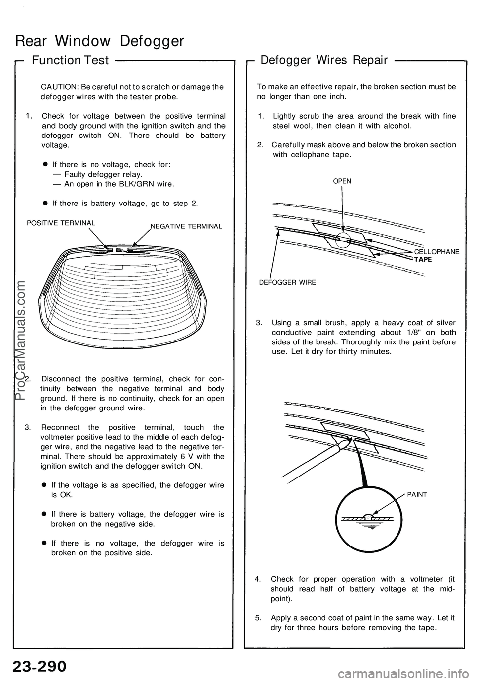
Check for voltage between the positive terminal
and body ground with the ignition switch and the
defogger switch ON. There should be battery
voltage.
If there is no voltage, check for:
— Faulty defogger relay.
— An open in the BLK/GRN wire.
If there is battery voltage, go to step 2.
POSITIVE TERMINAL
NEGATIVE TERMINAL
2. Disconnect the positive terminal, check for con-
tinuity between the negative terminal and body
ground. If there is no continuity, check for an open
in the defogger ground wire.
3. Reconnect the positive terminal, touch the
voltmeter positive lead to the middle of each defog-
ger wire, and the negative lead to the negative ter-
minal. There should be approximately 6 V with the
ignition switch and the defogger switch ON.
If the voltage is as specified, the defogger wire
is OK.
If there is battery voltage, the defogger wire is
broken on the negative side.
If there is no voltage, the defogger wire is
broken on the positive side.
Defogger Wires Repair
To make an effective repair, the broken section must be
no longer than one inch.
1. Lightly scrub the area around the break with fine
steel wool, then clean it with alcohol.
2. Carefully mask above and below the broken section
with cellophane tape.
OPEN
CELLOPHANE
DEFOGGER WIRE
3. Using a small brush, apply a heavy coat of silver
conductive paint extending about 1/8" on both
sides of the break. Thoroughly mix the paint before
use. Let it dry for thirty minutes.
PAINT
4. Check for proper operation with a voltmeter (it
should read half of battery voltage at the mid-
point).
5. Apply a second coat of paint in the same way. Let it
dry for three hours before removing the tape.ProCarManuals.com
Page 1431 of 1503
Wipers/Washers
Component Locatio n Inde x
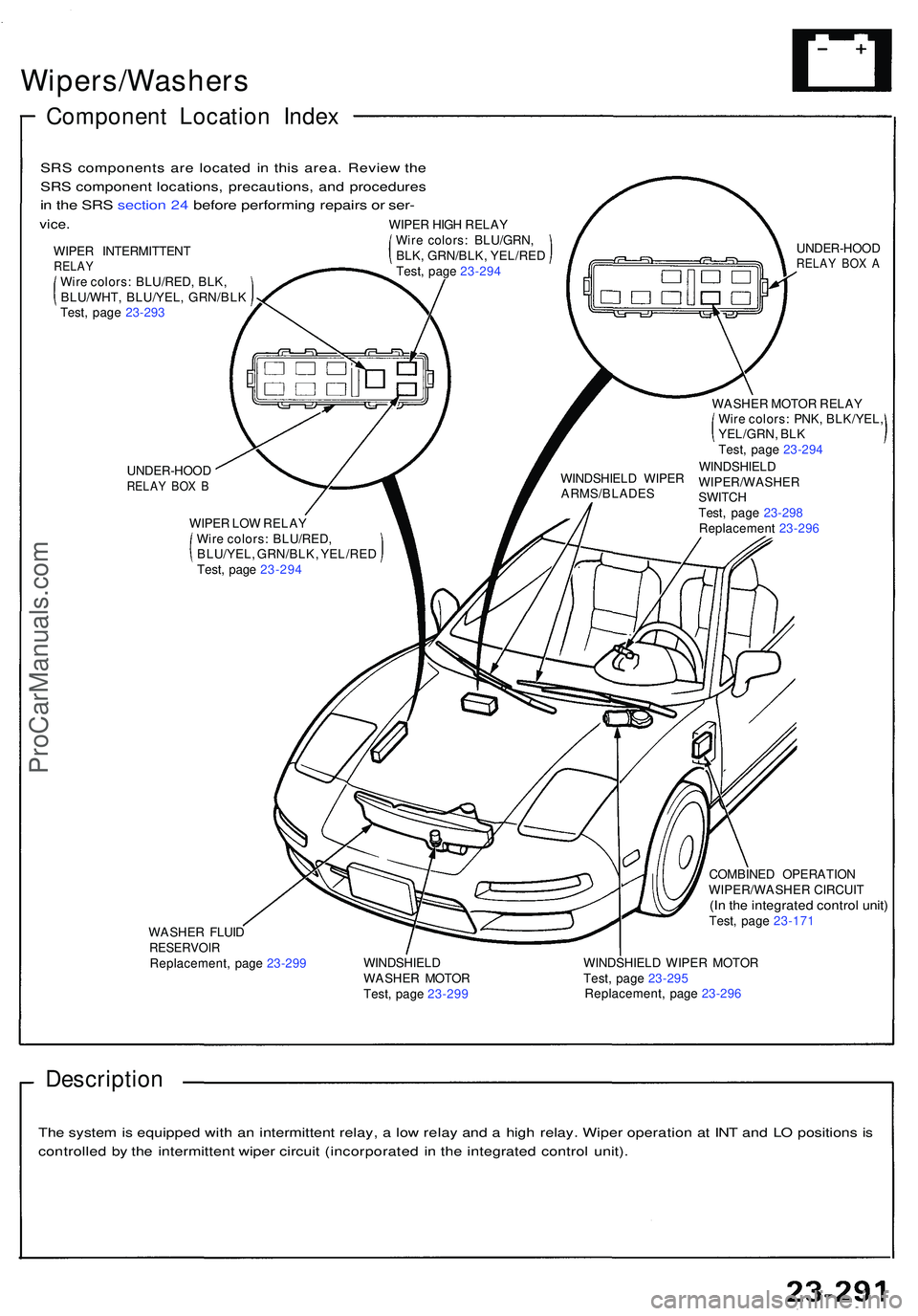
UNDER-HOO DRELAY BO X B
WIPE R LO W RELA Y
Wir e colors : BLU/RED ,
BLU/YEL , GRN/BLK , YEL/RE D
Test , pag e 23-29 4 WASHE
R MOTO R RELA Y
Wir e colors : PNK , BLK/YEL ,
YEL/GRN , BL K
Test , pag e 23-29 4
WINDSHIEL D
WIPER/WASHE R
SWITC H
Test , pag e 23-29 8
Replacemen t 23-29 6
WINDSHIEL
D WIPE R
ARMS/BLADE S UNDER-HOO
D
RELAY BO X A
WASHE R FLUI DRESERVOI RReplacement , pag e 23-29 9 COMBINE
D OPERATIO N
WIPER/WASHE R CIRCUI T
(In th e integrate d contro l unit )Test , pag e 23-17 1
WINDSHIEL D
WASHE R MOTO R
Test , pag e 23-29 9 WINDSHIEL
D WIPE R MOTO R
Test , pag e 23-29 5
Replacement , pag e 23-29 6
Descriptio n
The syste m is equippe d wit h a n intermitten t relay , a lo w rela y an d a hig h relay . Wipe r operatio n a t IN T an d L O position s i s
controlle d b y th e intermitten t wipe r circui t (incorporate d i n th e integrate d contro l unit) .
SR
S component s ar e locate d i n thi s area . Revie w th e
SR S componen t locations , precautions , an d procedure s
in th e SR S sectio n 24 befor e performin g repair s o r ser -
vice .
WIPE R INTERMITTEN TRELAYWire colors : BLU/RED , BLK ,
BLU/WHT , BLU/YEL , GRN/BL K
Test, pag e 23-29 3 WIPE
R HIG H RELA Y
Wir e colors : BLU/GRN ,
BLK , GRN/BLK , YEL/RE D
Test , pag e 23-29 4
ProCarManuals.com
Page 1432 of 1503
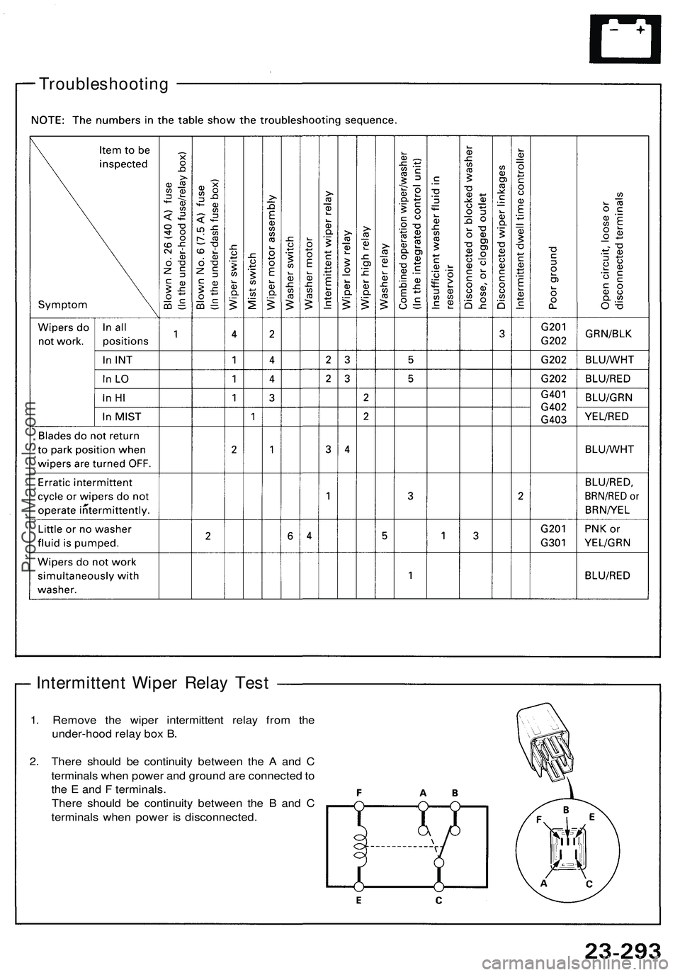
1. Remove the wiper intermittent relay from the
under-hood relay box B.
2. There should be continuity between the A and C
terminals when power and ground are connected to
the E and F terminals.
There should be continuity between the B and C
terminals when power is disconnected.
Troubleshooting
Intermittent Wiper Relay TestProCarManuals.com
Page 1433 of 1503
Wiper/Washer
High Relay/Washer Relay Test
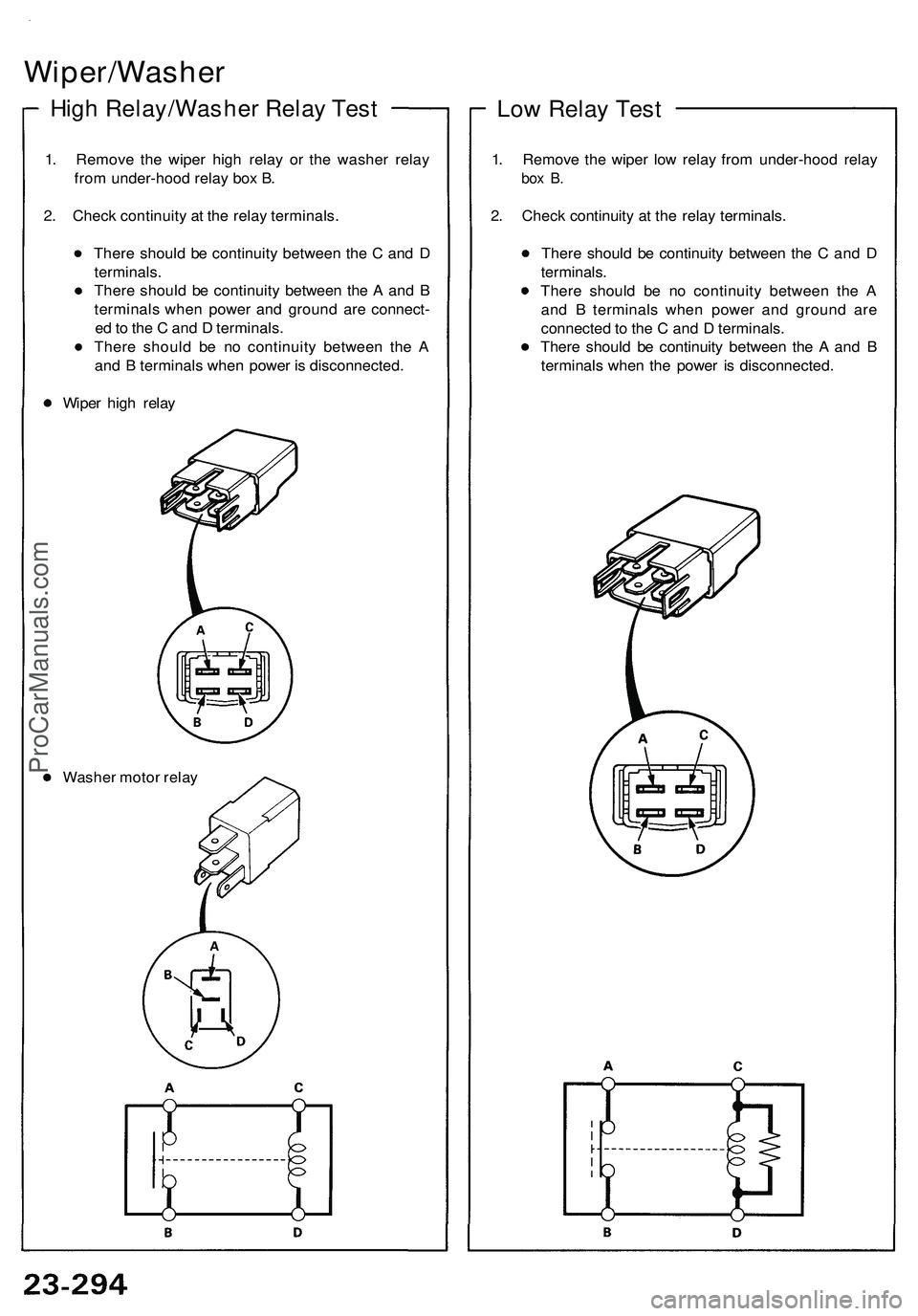
1. Remove the wiper high relay or the washer relay
from under-hood relay box B.
2. Check continuity at the relay terminals.
There should be continuity between the C and D
terminals.
There should be continuity between the A and B
terminals when power and ground are connect-
ed to the C and D terminals.
There should be no continuity between the A
and B terminals when power is disconnected.
Wiper high relay
Washer motor relay
Low Relay Test
1. Remove the wiper low relay from under-hood relay
box B.
2. Check continuity at the relay terminals.
There should be continuity between the C and D
terminals.
There should be no continuity between the A
and B terminals when power and ground are
connected to the C and D terminals.
There should be continuity between the A and B
terminals when the power is disconnected.ProCarManuals.com
Page 1452 of 1503
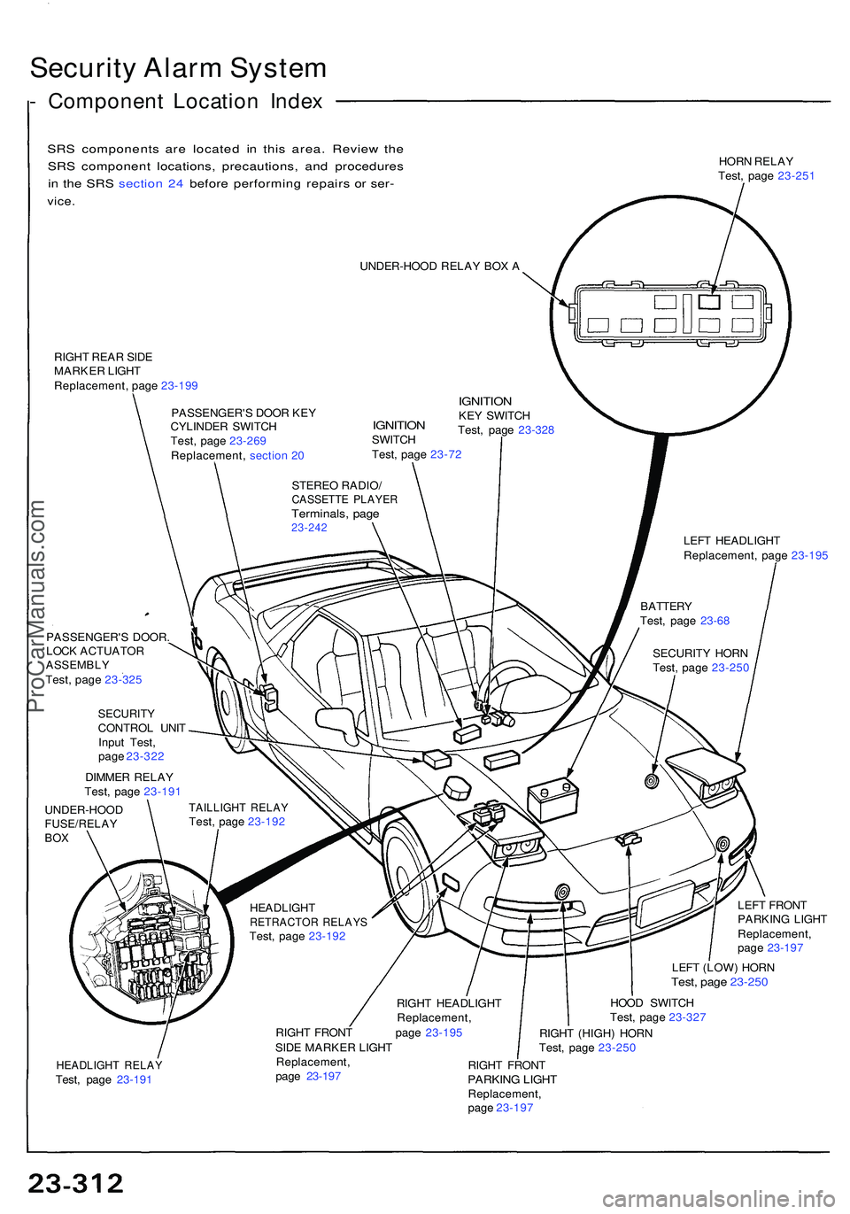
Security Alar m Syste m
- Componen t Locatio n Inde x
SRS component s ar e locate d i n thi s area . Revie w th e
SR S componen t locations , precautions , an d procedure s
i n th e SR S sectio n 24 befor e performin g repair s o r ser -
vice .
HOR N RELA Y
Test , pag e 23-25 1
UNDER-HOO D RELA Y BO X A
RIGH T REA R SID E
MARKE R LIGH T
Replacement , pag e 23-19 9
PASSENGER' S DOO R KE Y
CYLINDE R SWITC H
Test , pag e 23-26 9
Replacement , sectio n 2 0
IGNITIO NSWITCH
Test , pag e 23-7 2
IGNITIO NKEY SWITC H
Test , pag e 23-32 8
STERE O RADIO /
CASSETT E PLAYE RTerminals , pag e23-24 2LEFT HEADLIGH T
Replacement , pag e 23-19 5
PASSENGER' S DOOR .
LOC K ACTUATO R
ASSEMBLYTest, pag e 23-32 5
SECURIT YCONTROL UNI T
Inpu t Test ,
pag e 23-32 2
DIMME R RELA Y
Test , pag e 23-19 1
UNDER-HOO D
FUSE/RELAYBOX
TAILLIGH T RELA YTest, pag e 23-19 2
HEADLIGH T
RETRACTO R RELAY STest, pag e 23-19 2
RIGHT HEADLIGH T
Replacement ,
RIGH T FRON T pag e 23-19 5
SID E MARKE R LIGH T LEF
T FRON T
PARKIN G LIGH T
Replacement ,
pag e 23-19 7
LEF T (LOW ) HOR N
Test, pag e 23-25 0
HOOD SWITC H
Test , pag e 23-32 7
RIGH T (HIGH ) HOR N
Test , pag e 23-25 0
HEADLIGH T RELA YTest, pag e 23-19 1 Replacement
,
pag e 23-19 7 RIGH
T FRON TPARKIN G LIGH TReplacement ,
pag e 23-19 7 SECURIT
Y HOR N
Test , pag e 23-25 0
BATTER
Y
Test , pag e 23-6 8
ProCarManuals.com
Page 1456 of 1503
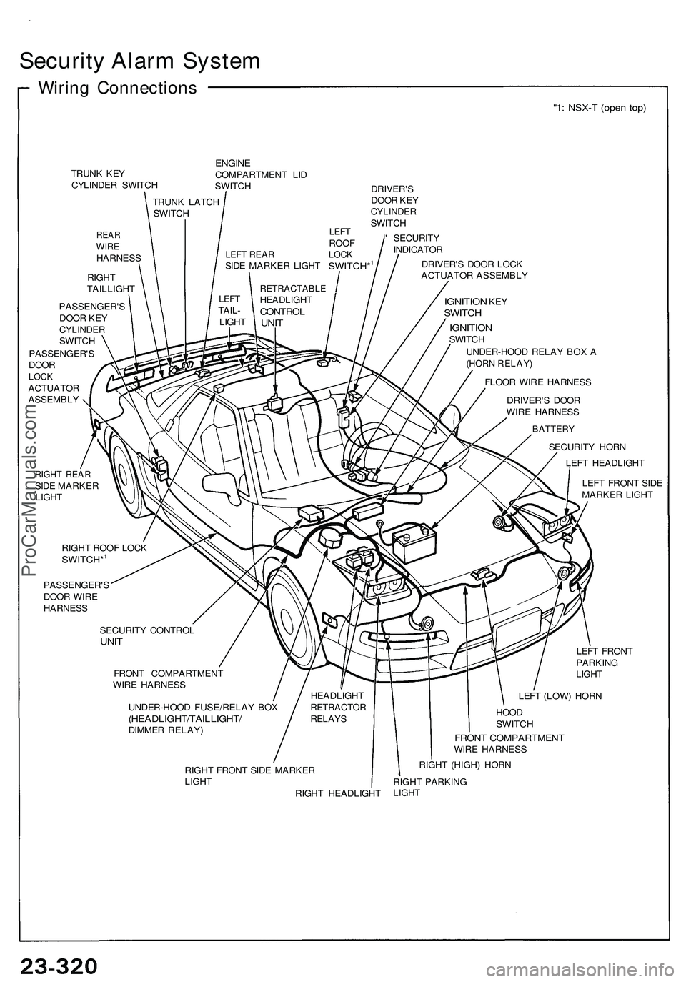
Security Alar m Syste m
Wiring Connection s
"1: NSX- T (ope n top )
TRUN K KE Y
CYLINDE R SWITC H
REARWIREHARNES S
RIGH T
TAILLIGH T
ENGINECOMPARTMEN T LI D
SWITC H
DRIVER'S
DOO R KE Y
CYLINDE RSWITCH
' SECURIT Y
INDICATO R
DRIVER' S DOO R LOC K
ACTUATO R ASSEMBL Y
PASSENGER' S
DOO R KE Y
CYLINDE RSWITCH
PASSENGER' S
DOO R
LOCKACTUATO R
ASSEMBL Y
IGNITION KEYSWITC H
IGNITIO NSWITCH
UNDER-HOO D RELA Y BO X A
(HOR N RELAY )
FLOOR WIR E HARNES S
DRIVER' S DOO R
WIR E HARNES S
RIGHT REA RSIDE MARKE R
LIGH T TRUN
K LATC H
SWITC H
RETRACTABL EHEADLIGHTCONTROLUNIT
LEF TTAIL -
LIGH T
HEADLIGHT
RETRACTO RRELAYS
BATTER Y
SECURIT Y HOR N
LEF T HEADLIGH T
LEF T FRON T SID E
MARKE R LIGH T
RIGH T ROO F LOC K
SWITCH*1
PASSENGER' S
DOO R WIR E
HARNES S
SECURIT Y CONTRO L
UNIT
FRON T COMPARTMEN T
WIR E HARNES S
UNDER-HOO D FUSE/RELA Y BO X
(HEADLIGHT/TAILLIGHT /DIMMER RELAY ) LEF
T FRON T
PARKIN G
LIGH T
LEF T (LOW ) HOR N
HOO DSWITC H
FRONT COMPARTMEN TWIRE HARNES S
RIGH T FRON T SID E MARKE R
LIGH T
RIGHT HEADLIGH TRIGH
T (HIGH ) HOR N
RIGH T PARKIN G
LIGH T
LEFT REA RSIDE MARKE R LIGH TSWITCH*1
LEFTROO FLOCK
ProCarManuals.com
Page 1466 of 1503
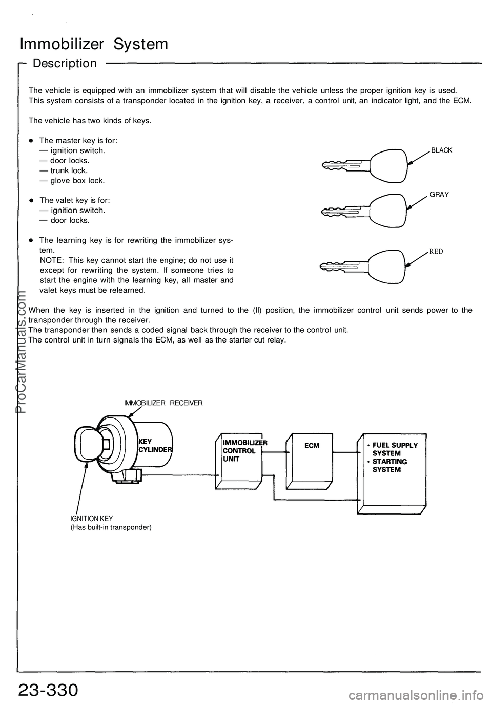
Immobilizer Syste m
Descriptio n
The vehicl e i s equippe d wit h a n immobilize r syste m tha t wil l disabl e th e vehicl e unles s th e prope r ignitio n ke y i s used .
Thi s syste m consist s o f a transponde r locate d i n th e ignitio n key , a receiver , a contro l unit , a n indicato r light , an d th e ECM .
Th e vehicl e ha s tw o kind s o f keys .
BLAC K
GRAY
The maste r ke y i s for :
— ignitio n switch .
— doo r locks .
— trun k lock .
— glov e bo x lock .
Th e vale t ke y i s for :
— ignitio n switch .
— doo r locks .
Th e learnin g ke y i s fo r rewritin g th e immobilize r sys -
tem.
NOTE : Thi s ke y canno t star t th e engine ; d o no t us e i t
excep t fo r rewritin g th e system . I f someon e trie s t o
star t th e engin e wit h th e learnin g key , al l maste r an d
vale t key s mus t b e relearned .
Whe n th e ke y i s inserte d i n th e ignitio n an d turne d t o th e (II ) position , th e immobilize r contro l uni t send s powe r t o th e
transponde r throug h th e receiver .
Th e transponde r the n send s a code d signa l bac k throug h th e receive r t o th e contro l unit .
Th e contro l uni t i n tur n signal s th e ECM , a s wel l a s th e starte r cu t relay .
RED
IMMOBILIZE R RECEIVE R
IGNITION KE Y(Has built-i n transponder )
23-330ProCarManuals.com
Page 1467 of 1503
IGNITION SWITCH
PROPER KEY
INSERTED
INDICATOR
LIGHT
WRONG KEY
INSERTED
INDICATOR
LIGHT
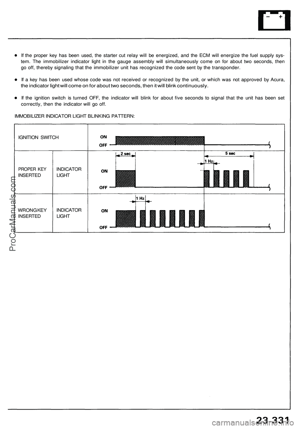
If the proper key has been used, the starter cut relay will be energized, and the ECM will energize the fuel supply sys-
tem. The immobilizer indicator light in the gauge assembly will simultaneously come on for about two seconds, then
go off, thereby signaling that the immobilizer unit has recognized the code sent by the transponder.
If a key has been used whose code was not received or recognized by the unit, or which was not approved by Acura,
the indicator light will come on for about two seconds, then it will blink continuously.
If the ignition switch is turned OFF, the indicator will blink for about five seconds to signal that the unit has been set
correctly, then the indicator will go off.
IMMOBILIZER INDICATOR LIGHT BLINKING PATTERN:ProCarManuals.com