relay ACURA NSX 1997 Service Manual PDF
[x] Cancel search | Manufacturer: ACURA, Model Year: 1997, Model line: NSX, Model: ACURA NSX 1997Pages: 1503, PDF Size: 57.08 MB
Page 1374 of 1503
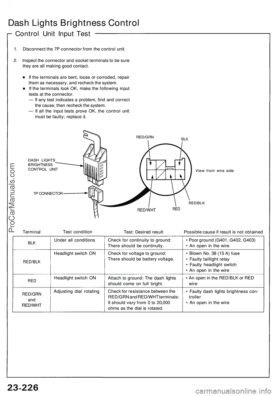
Dash Lights Brightness Control
Control Unit Input Test
1. Disconnect the 7P connector from the control unit.
2. Inspect the connector and socket terminals to be sure
they are all making good contact.
If the terminals are bent, loose or corroded, repair
them as necessary, and recheck the system.
If the terminals look OK, make the following input
tests at the connector.
— If any test indicates a problem, find and correct
the cause, then recheck the system.
— If all the input tests prove OK, the control unit
must be faulty; replace it.
BLK
DASH LIGHTS
BRIGHTNESS
CONTROL UNIT
7P CONNECTOR
View from wire side
RED/BLK
Terminal
Test condition
RED/WHT
Test: Desired result
RED
Possible cause if result is not obtained
BLK
RED/BLK
RED
RED/GRN
and
RED/WHT
Under all conditions
Headlight switch ON
Headlight switch ON
Adjusting dial rotating
Check for continuity to ground:
There should be continuity.
Check for voltage to ground:
There should be battery voltage.
Attach to ground: The dash lights
should come on full bright.
Check for resistance between the
RED/GRN and RED/WHT terminals:
It should vary from 0 to 20,000
ohms as the dial is rotated.
• Poor ground (G401, G402, G403)
• An open in the wire
• Blown No. 38 (15 A) fuse
• Faulty taillight relay
• Faulty headlight switch
• An open in the wire
• An open in the RED/BLK or RED
wire
• Faulty dash lights brightness con-
troller
• An open in the wire
RED/GRNProCarManuals.com
Page 1381 of 1503
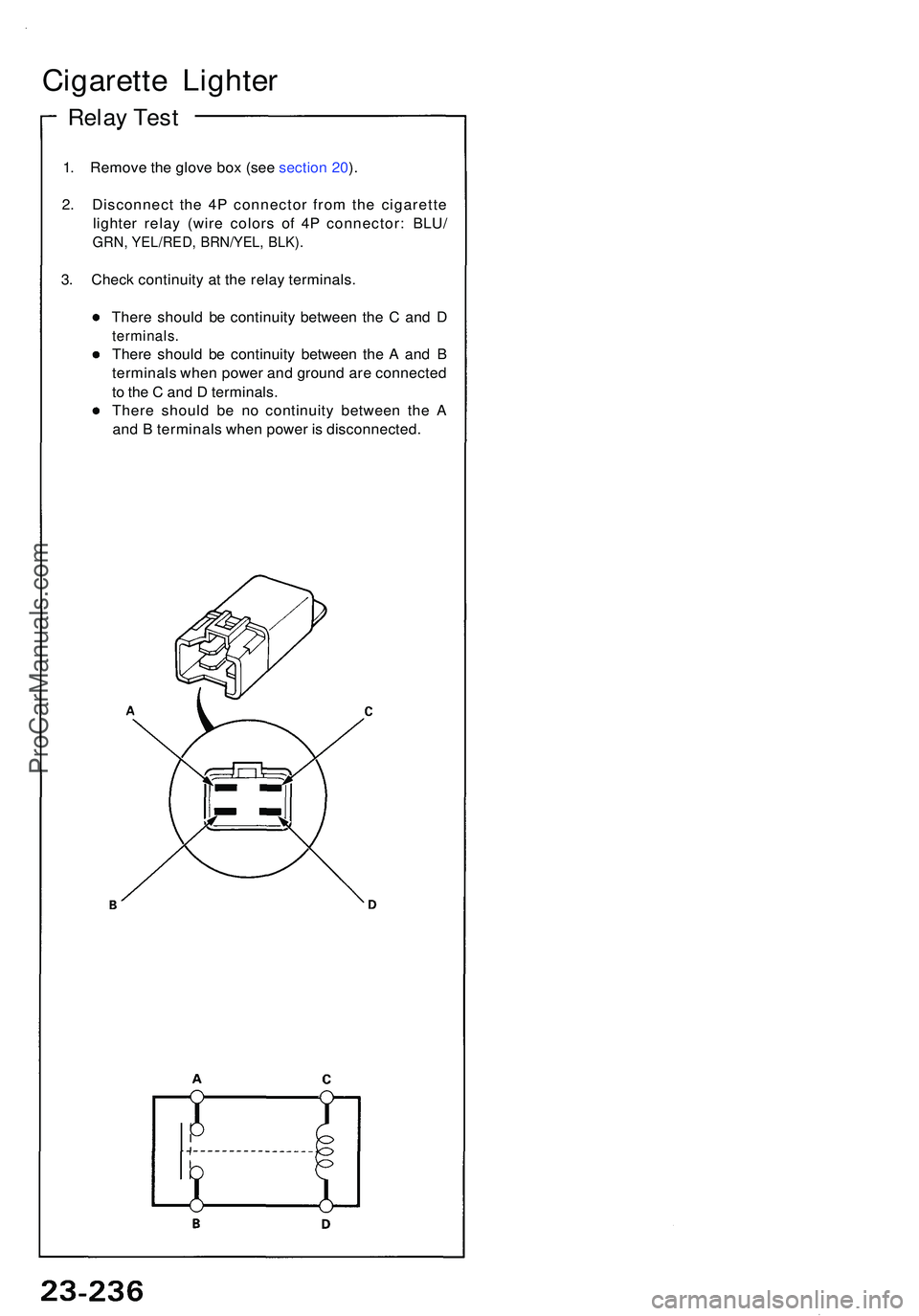
1. Remov e th e glov e bo x (se e sectio n 20 ).
2 . Disconnec t th e 4 P connecto r fro m th e cigarett e
lighte r rela y (wir e color s of 4P connector : BLU /
GRN, YEL/RED , BRN/YEL , BLK) .
3. Chec k continuit y a t th e rela y terminals .
Ther e shoul d b e continuit y betwee n th e C an d D
terminals .
There shoul d b e continuit y betwee n th e A an d B
terminal s whe n powe r an d groun d ar e connecte d
t o th e C an d D terminals .
Ther e shoul d b e n o continuit y betwee n th e A
an d B terminal s whe n powe r i s disconnected .
Cigarette Lighte r
Relay Tes t
ProCarManuals.com
Page 1382 of 1503
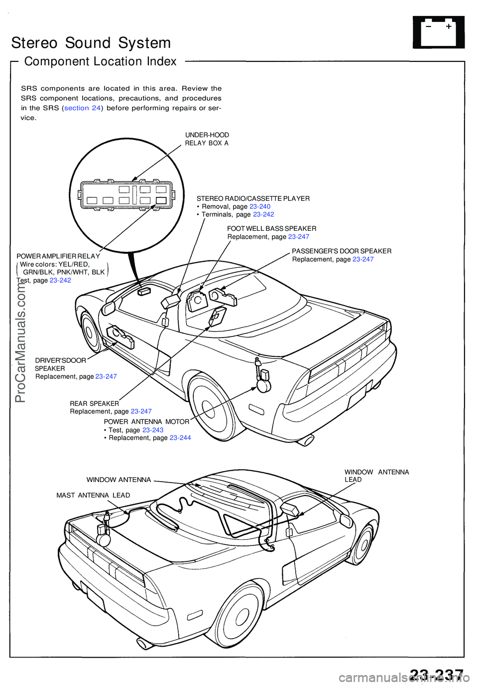
Stereo Soun d Syste m
Componen t Locatio n Inde x
SRS component s ar e locate d i n thi s area . Revie w th e
SR S componen t locations , precautions , an d procedure s
i n th e SR S ( sectio n 24 ) befor e performin g repair s o r ser -
vice .
UNDER-HOO DRELAY BO X A
STERE O RADIO/CASSETT E PLAYE R
• Removal , pag e 23-24 0
• Terminals , pag e 23-24 2
FOO T WEL L BAS S SPEAKE R
Replacement , pag e 23-247
POWE R AMPLIFIE R RELA Y
Wir e colors : YEL/RED ,
GRN/BLK , PNK/WHT , BL K
Test , pag e 23-24 2 PASSENGER'
S DOO R SPEAKE R
Replacement , pag e 23-24 7
DRIVER'SDOO RSPEAKERReplacement , pag e 23-24 7
REAR SPEAKE RReplacement , pag e 23-24 7
POWE R ANTENN A MOTO R
• Test , pag e 23-24 3
• Replacement , pag e 23-24 4
WINDO W ANTENN A
MAST ANTENN A LEA D WINDO
W ANTENN A
LEAD
ProCarManuals.com
Page 1385 of 1503
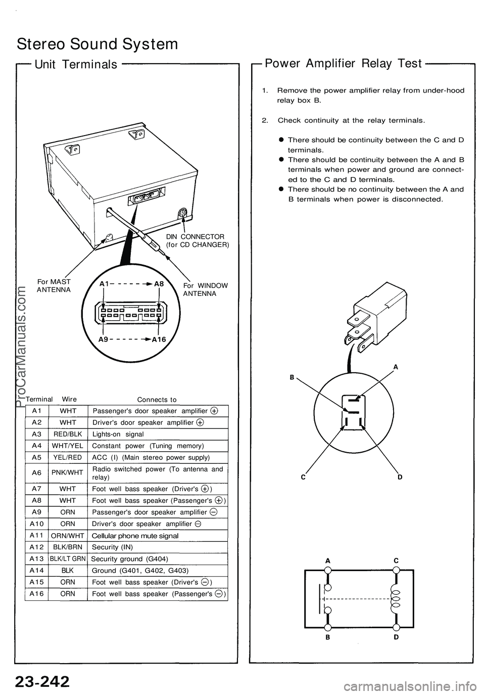
Stereo Sound System
Unit Terminals
For MAST
ANTENNA
DIN CONNECTOR
(for CD CHANGER)
For WINDOW
ANTENNA
Terminal Wire
Connects to
A1
A2
A3
A4
A5
A6
A7
A8
A9
A10
A11
A12
A13
A14
A15
A16
WHT
WHT
RED/BLK
WHT/YEL
YEL/RED
PNK/WHT
WHT
WHT
ORN
ORN
ORN/WHT
BLK/BRN
BLK/LT GRN
BLK
ORN
ORN
Passenger's door speaker amplifier
Driver's door speaker amplifier
Lights-on signal
Constant power (Tuning memory)
ACC (I) (Main stereo power supply)
Radio switched power (To antenna and
relay)
Foot well bass speaker (Driver's )
Foot well bass speaker (Passenger's )
Passenger's door speaker amplifier
Driver's door speaker amplifier
Cellular phone mute signal
Security (IN)
Security ground (G404)
Ground (G401, G402, G403)
Foot well bass speaker (Driver's )
Foot well bass speaker (Passenger's )
Power Amplifier Relay Test
1. Remove the power amplifier relay from under-hood
relay box B.
2. Check continuity at the relay terminals.
There should be continuity between the C and D
terminals.
There should be continuity between the A and B
terminals when power and ground are connect-
ed to the C and D terminals.
There should be no continuity between the A and
B terminals when power is disconnected.ProCarManuals.com
Page 1392 of 1503
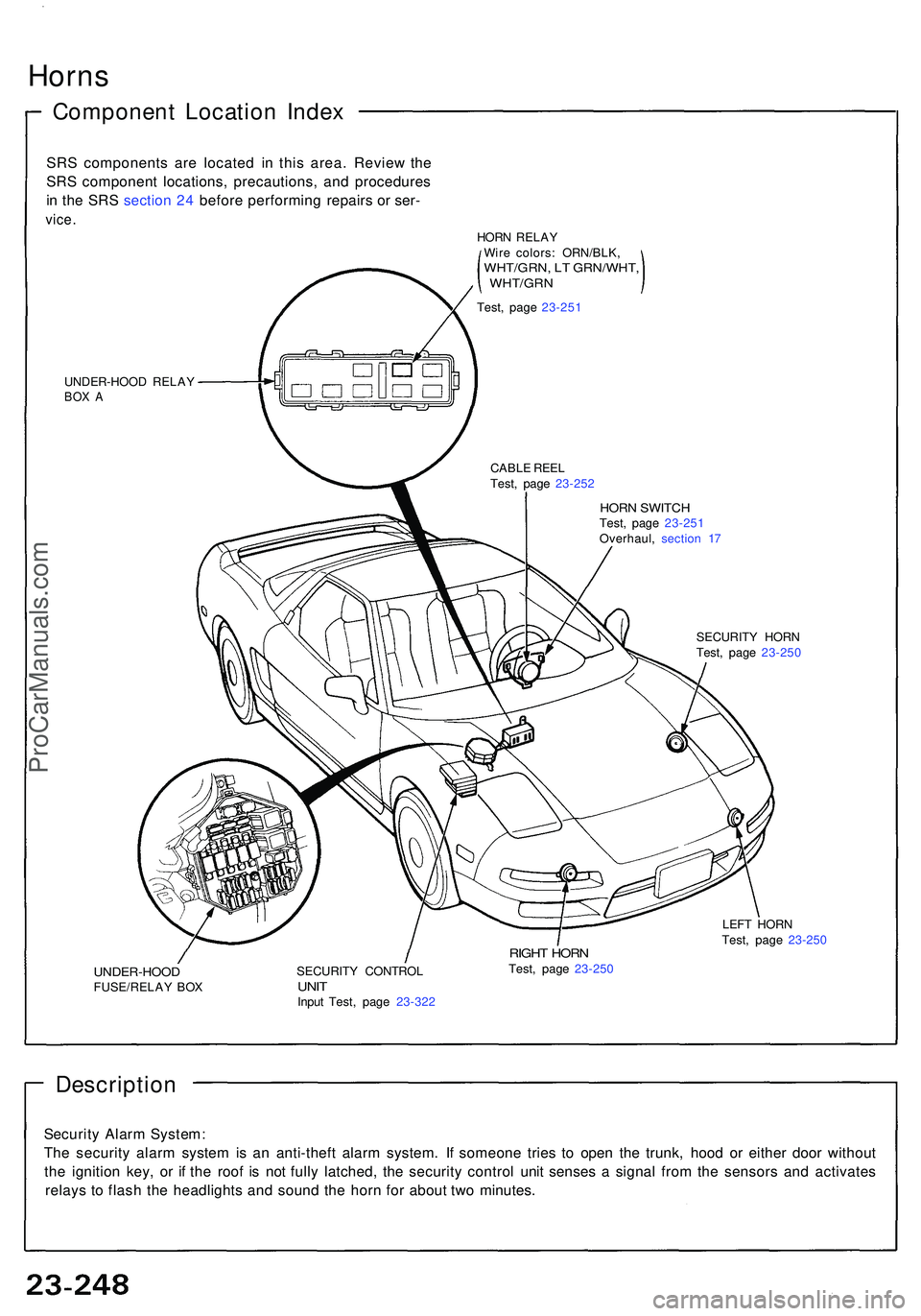
Horns
Componen t Locatio n Inde x
SRS component s ar e locate d i n thi s area . Revie w th e
SR S componen t locations , precautions , an d procedure s
i n th e SR S sectio n 24 befor e performin g repair s o r ser -
vice .
UNDER-HOO D RELA YBOX A
HOR N SWITC HTest, pag e 23-25 1
Overhaul , sectio n 1 7
CABL
E REE L
Test , pag e 23-25 2
SECURITY HOR N
Test , pag e 23-25 0
UNDER-HOO DFUSE/RELAY BO X SECURIT
Y CONTRO LUNITInpu t Test , pag e 23-32 2
RIGHT HOR NTest, pag e 23-25 0 LEF
T HOR N
Test , pag e 23-25 0
Descriptio n
Security Alar m System :
Th e securit y alar m syste m is a n anti-thef t alar m system . I f someon e trie s t o ope n th e trunk , hoo d o r eithe r doo r withou t
th e ignitio n key , o r i f th e roo f i s no t full y latched , th e securit y contro l uni t sense s a signa l fro m th e sensor s an d activate s
relay s t o flas h th e headlight s an d soun d th e hor n fo r abou t tw o minutes .
HORN RELA Y
Wir e colors : ORN/BLK ,
WHT/GRN, L T GRN/WHT ,, WHT/GR N
Test, pag e 23-25 1
ProCarManuals.com
Page 1394 of 1503
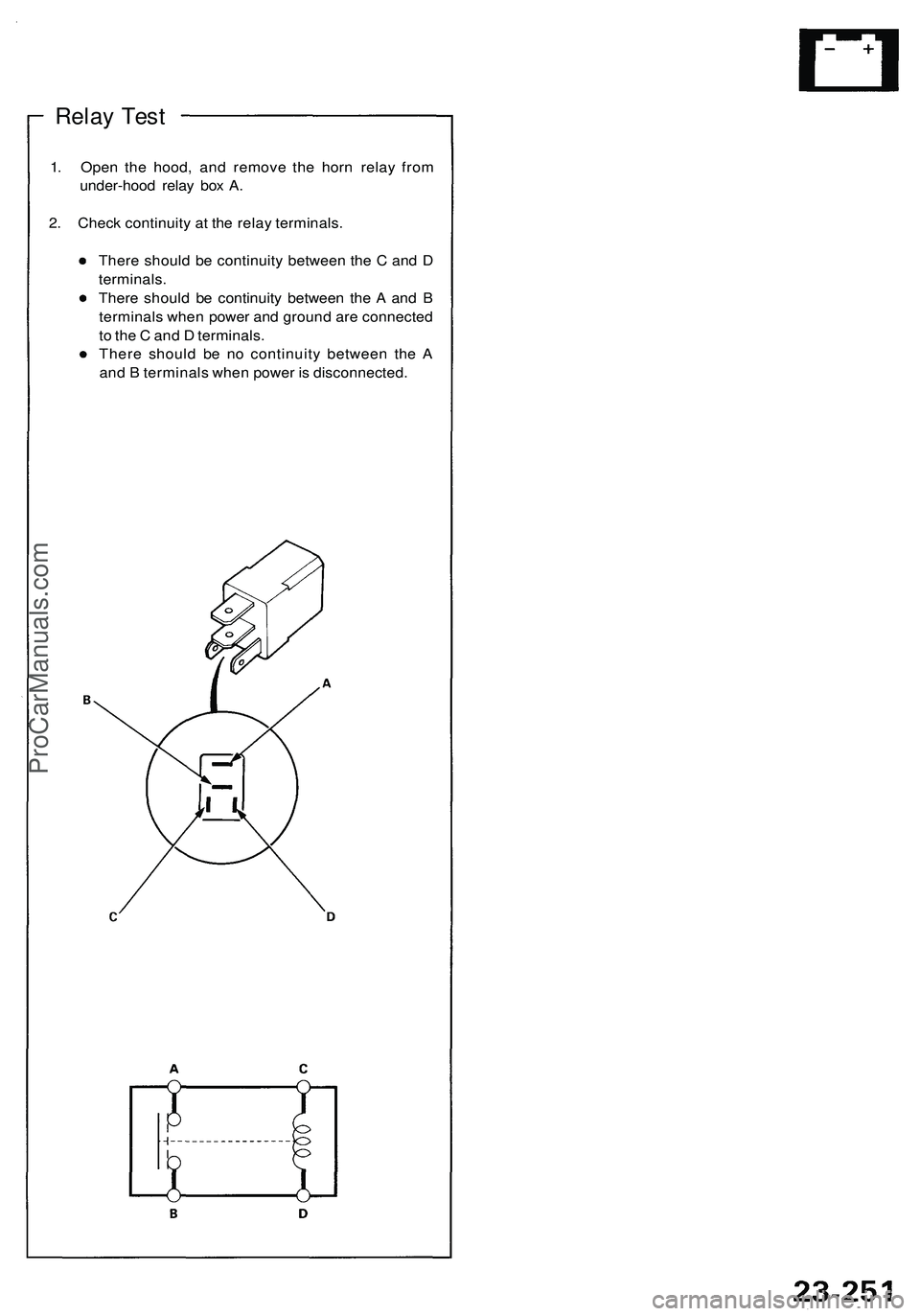
Relay Test
1. Open the hood, and remove the horn relay from
under-hood relay box A.
2. Check continuity at the relay terminals.
There should be continuity between the C and D
terminals.
There should be continuity between the A and B
terminals when power and ground are connected
to the C and D terminals.
There should be no continuity between the A
and B terminals when power is disconnected.ProCarManuals.com
Page 1413 of 1503
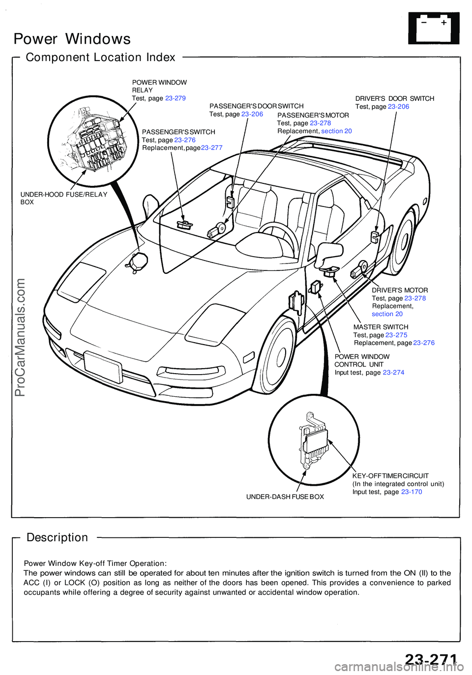
Power Window s
Componen t Locatio n Inde x
POWE R WINDO WRELAYTest, pag e 23-27 9
PASSENGER' S DOO R SWITC H DRIVER'
S DOO R SWITC H
Test , pag e 23-20 6
UNDER-HOO D FUSE/RELA YBOX
Test , pag e 23-20 6
PASSENGER' S MOTO R
Test , pag e 23-27 8
Replacement , sectio n 2 0
PASSENGER' S SWITC H
Test , pag e 23-27 6
Replacement , pag e 23-27 7
DRIVER'S MOTO R
Test , pag e 23-27 8
Replacement ,section 2 0
MASTE R SWITC H
Test , pag e 23-27 5
Replacement , pag e 23-27 6
POWE R WINDO W
CONTRO L UNI T
Inpu t test , pag e 23-27 4
UNDER-DAS H FUS E BO X KEY-OF
F TIME R CIRCUI T
(I n th e integrate d contro l unit )
Inpu t test , pag e 23-17 0
Descriptio n
Power Windo w Key-of f Time r Operation :
The powe r window s ca n stil l b e operate d fo r abou t te n minute s afte r th e ignitio n switc h is turne d fro m th e O N (II ) t o th e
AC C (I ) o r LOC K (O ) positio n a s lon g a s neithe r o f th e door s ha s bee n opened . Thi s provide s a convenienc e t o parke d
occupant s whil e offerin g a degre e o f securit y agains t unwante d o r accidenta l windo w operation .
ProCarManuals.com
Page 1415 of 1503
Power Windows
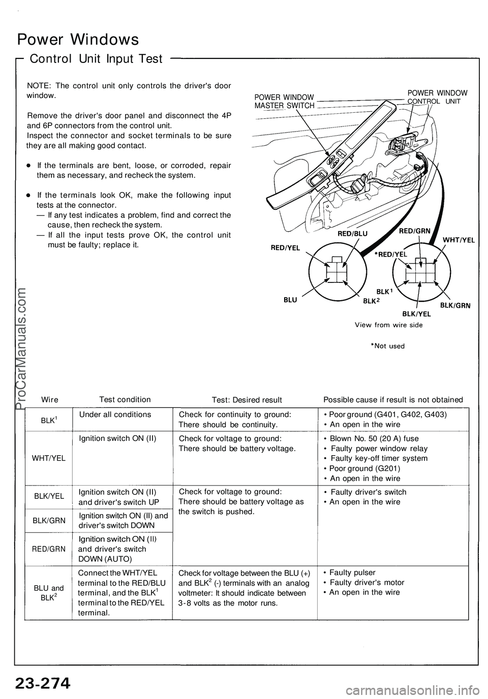
Control Unit Input Test
NOTE: The control unit only controls the driver's door
window.
Remove the driver's door panel and disconnect the 4P
and 6P connectors from the control unit.
Inspect the connector and socket terminals to be sure
they are all making good contact.
If the terminals are bent, loose, or corroded, repair
them as necessary, and recheck the system.
If the terminals look OK, make the following input
tests at the connector.
— If any test indicates a problem, find and correct the
cause, then recheck the system.
— If all the input tests prove OK, the control unit
must be faulty; replace it.
POWER WINDOW
MASTER SWITCH
POWER WINDOW
CONTROL UNIT
Wire
Test condition
Test: Desired result
Possible cause if result is not obtained
BLK1
Under all conditions
Check for continuity to ground:
There should be continuity.
• Poor ground (G401, G402, G403)
• An open in the wire
Ignition switch ON (II)
Check for voltage to ground:
There should be battery voltage.
WHT/YEL
• Blown No. 50 (20 A) fuse
• Faulty power window relay
• Faulty key-off timer system
• Poor ground (G201)
• An open in the wire
BLK/YEL
Ignition switch ON (II)
and driver's switch UP
BLK/GRN
Ignition switch ON (II) and
driver's switch DOWN
Check for voltage to ground:
There should be battery voltage as
the switch is pushed.
• Faulty driver's switch
• An open in the wire
RED/GRN
Ignition switch ON (
and driver's switch
DOWN (AUTO)
BLU and
BLK2
Connect the WHT/YEL
terminal to the RED/BLU
terminal, and the BLK1
terminal to the RED/YEL
terminal.
Check for voltage between the BLU (+)
and BLK2 (-) terminals with an analog
voltmeter: It should indicate between
3-8 volts as the motor runs.
• Faulty pulser
• Faulty driver's motor
• An open in the wireProCarManuals.com
Page 1420 of 1503
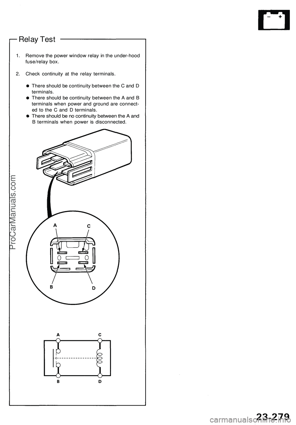
Relay Test
1. Remove the power window relay in the under-hood
fuse/relay box.
2. Check continuity at the relay terminals.
There should be continuity between the C and D
terminals.
There should be continuity between the A and B
terminals when power and ground are connect-
ed to the C and D terminals.
There should be no continuity between the A and
B terminals when power is disconnected.ProCarManuals.com
Page 1428 of 1503
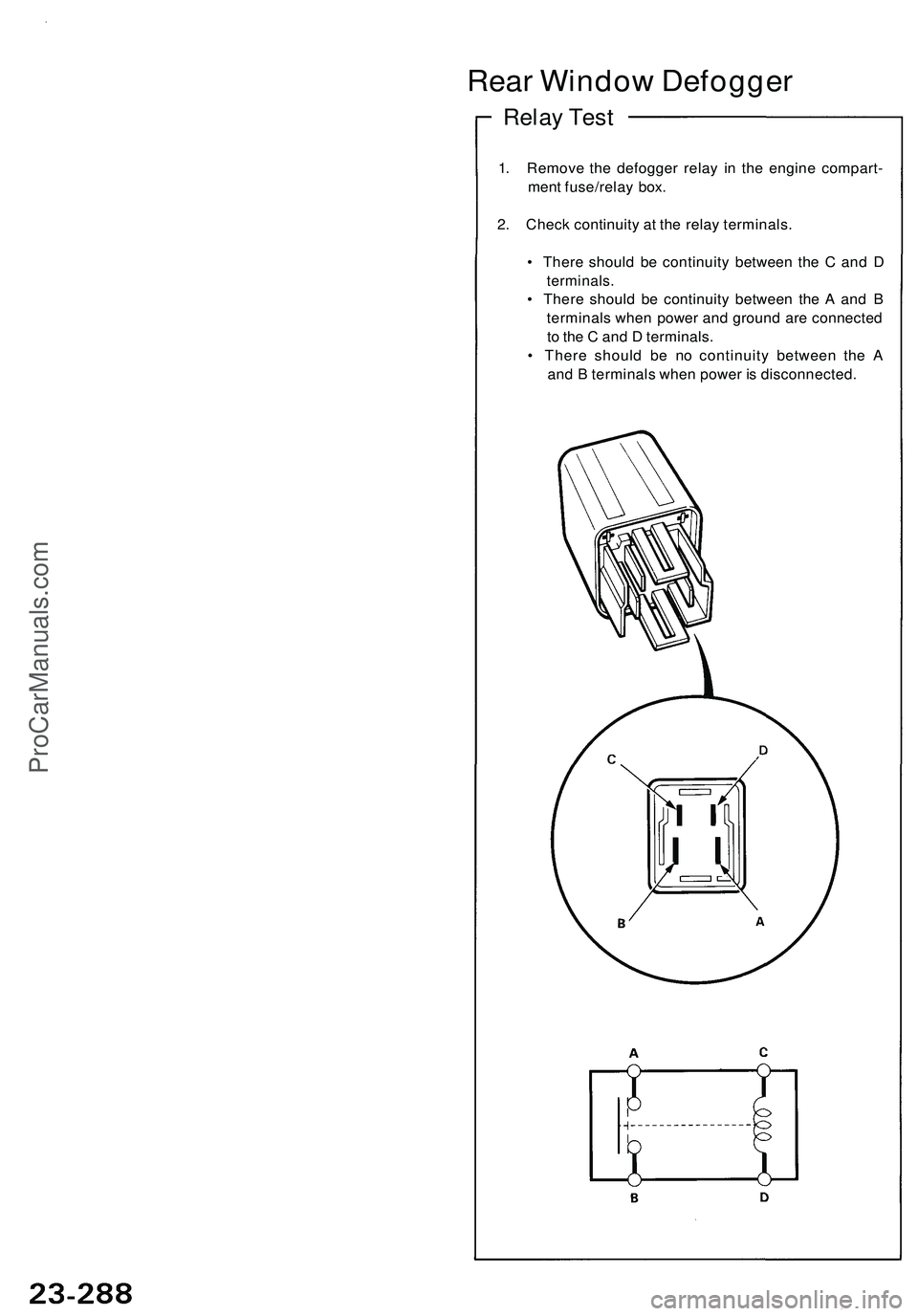
Rear Windo w Defogge r
Relay Tes t
1. Remov e th e defogge r rela y i n th e engin e compart -
men t fuse/rela y box .
2 . Chec k continuit y a t th e rela y terminals .
• Ther e shoul d b e continuit y betwee n th e C an d D
terminals .
• Ther e shoul d b e continuit y betwee n th e A an d B
terminal s whe n powe r an d groun d ar e connecte d
t o th e C an d D terminals .
• Ther e shoul d b e n o continuit y betwee n th e A
an d B terminal s whe n powe r i s disconnected .
ProCarManuals.com