air condition ACURA NSX 1997 Service Repair Manual
[x] Cancel search | Manufacturer: ACURA, Model Year: 1997, Model line: NSX, Model: ACURA NSX 1997Pages: 1503, PDF Size: 57.08 MB
Page 1 of 1503
General Info
Specifications
Maintenance
Engine
Cooling
Fuel and Emissions
*Transaxle
SteeringSuspension
*Brakes (Including ABS)
*Body
*Heating, Ventilation and
Air Conditioning
*Body Electrical
*Engine Electrical
*SRS
1997-200 5 NSX Main Menu
As sections w/ * include SRS components,
special precautions are required when servicing.
ProCarManuals.com
Page 55 of 1503
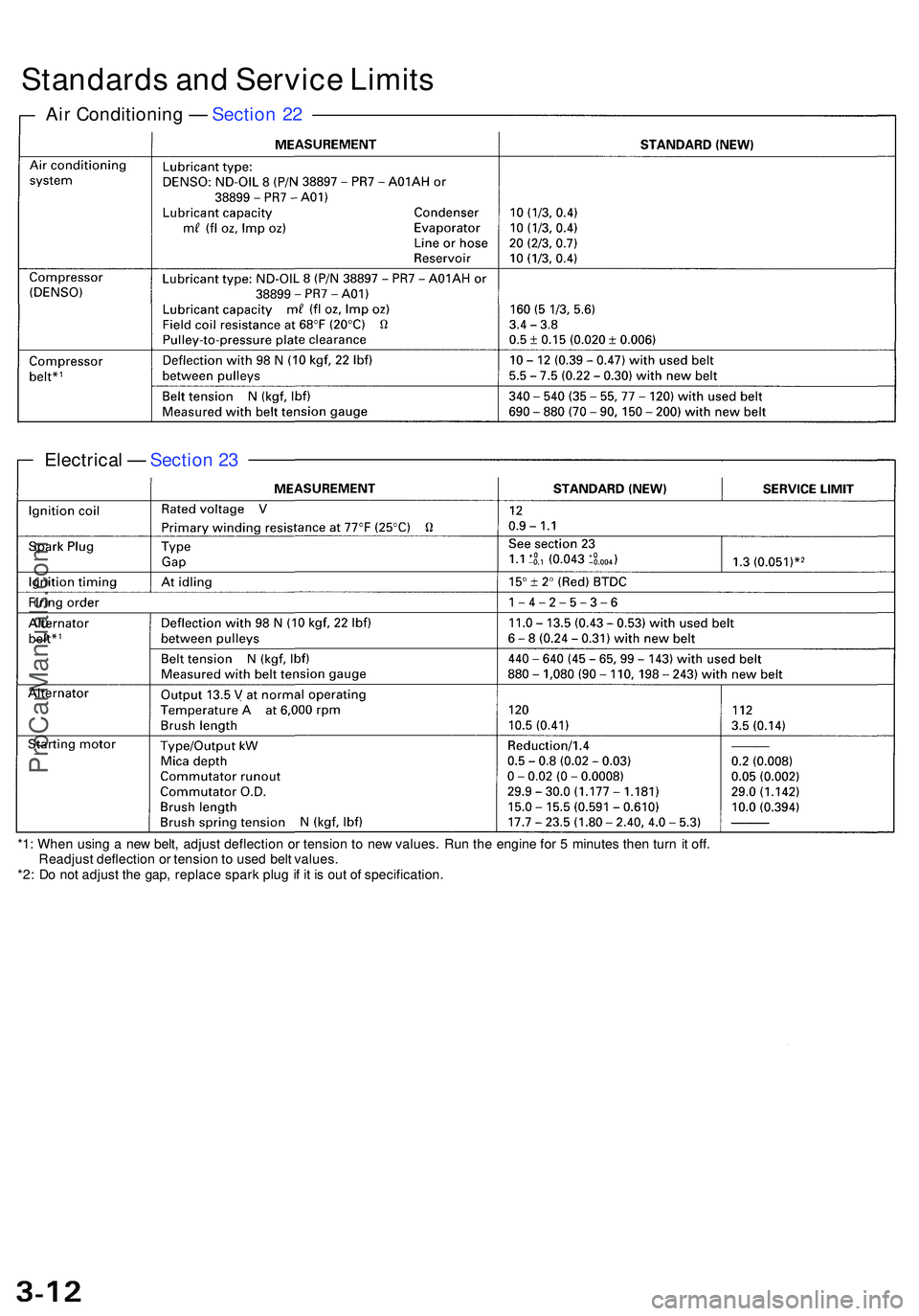
Standards an d Servic e Limit s
Air Conditionin g — Sectio n 2 2
Electrica l — Sectio n 2 3
*1 : Whe n usin g a ne w belt , adjus t deflectio n o r tensio n t o ne w values . Ru n th e engin e fo r 5 minute s the n tur n it off .
Readjus t deflectio n o r tensio n to use d bel t values .
*2 : D o no t adjus t th e gap , replac e spar k plu g if i t i s ou t o f specification .
ProCarManuals.com
Page 141 of 1503
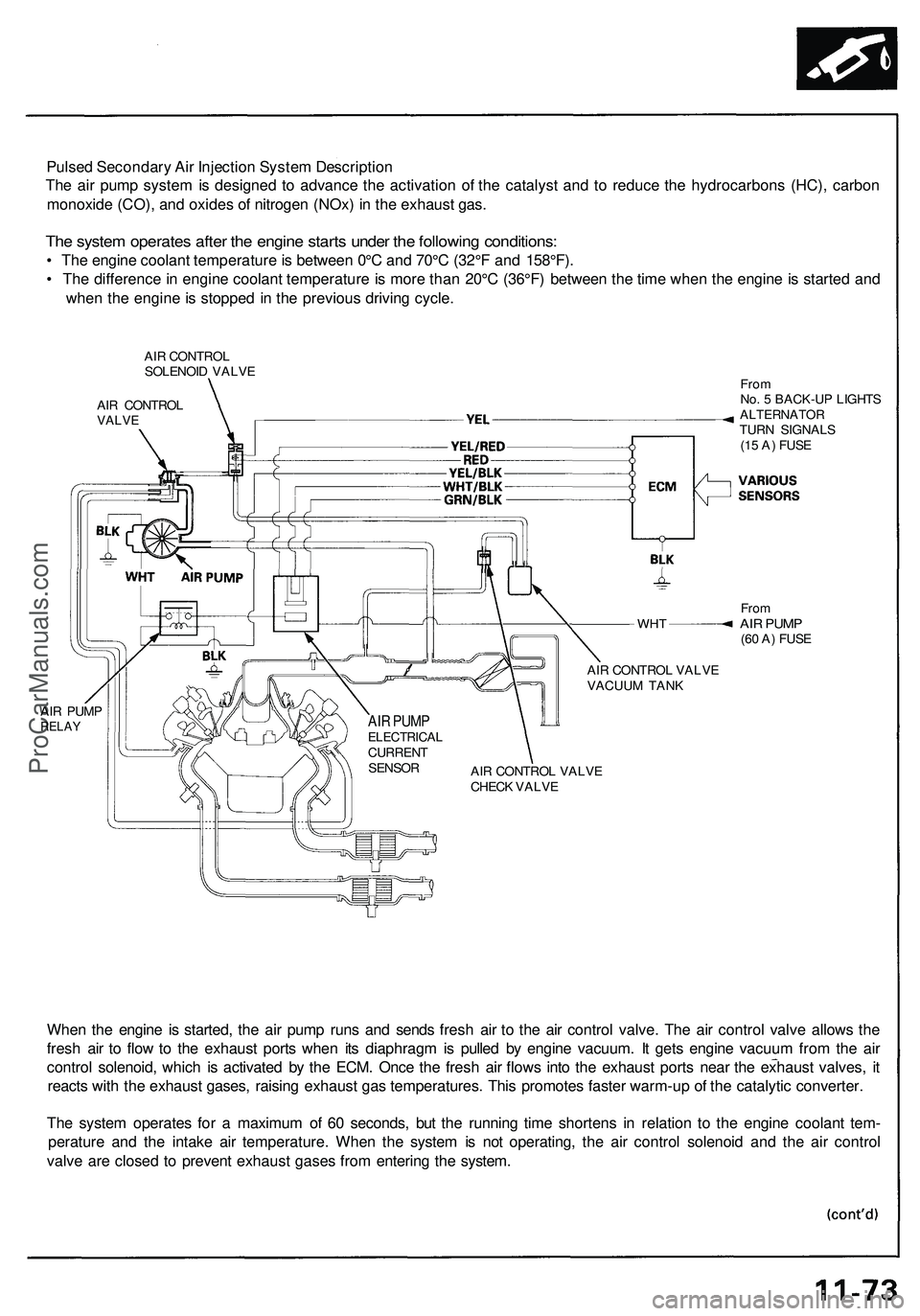
Pulsed Secondary Air Injection System Description
The air pump system is designed to advance the activation of the catalyst and to reduce the hydrocarbons (HC), carbon
monoxide (CO), and oxides of nitrogen (NOx) in the exhaust gas.
The system operates after the engine starts under the following conditions:
• The engine coolant temperature is between 0°C and 70°C (32°F and 158°F).
• The difference in engine coolant temperature is more than 20°C (36°F) between the time when the engine is started and
when the engine is stopped in the previous driving cycle.
AIR CONTROL
SOLENOID VALVE
AIR CONTROL
VALVE
WHT
AIR PUMP
RELAY
From
No. 5 BACK-UP LIGHTS
ALTERNATOR
TURN SIGNALS
(15 A) FUSE
From
AIR PUMP
(60 A) FUSE
AIR CONTROL VALVE
VACUUM TANK
AIR CONTROL VALVE
CHECK VALVE
When the engine is started, the air pump runs and sends fresh air to the air control valve. The air control valve allows the
fresh air to flow to the exhaust ports when its diaphragm is pulled by engine vacuum. It gets engine vacuum from the air
control solenoid, which is activated by the ECM. Once the fresh air flows into the exhaust ports near the exhaust valves, it
reacts with the exhaust gases, raising exhaust gas temperatures. This promotes faster warm-up of the catalytic converter.
The system operates for a maximum of 60 seconds, but the running time shortens in relation to the engine coolant tem-
perature and the intake air temperature. When the system is not operating, the air control solenoid and the air control
valve are closed to prevent exhaust gases from entering the system.
AIR PUMP
ELECTRICAL
CURRENT
SENSORProCarManuals.com
Page 145 of 1503
Troubleshooting Precaution s
EPS Indicato r Ligh t
Unde r norma l conditions , th e EP S indicato r i n th e gaug e assembl y come s o n whe n th e ignitio n switc h is turne d t o th e O N
(II ) position , the n goe s of f afte r th e engin e i s started . Thi s indicate s tha t th e bul b an d it s circuit s ar e operatin g correctly . I f
ther e i s an y troubl e i n th e system , th e EP S indicato r turn s o n durin g driving , an d th e powe r steerin g assis t i s turne d off .
Whe n th e EP S indicato r come s on , th e contro l uni t memorize s th e DTC . I n thi s case , th e contro l uni t doe s no t activat e th e
EP S syste m afte r th e engin e start s agai n bu t i t keep s th e EP S indicato r on .
Whe n a proble m is detected , th e EP S indicato r come s on . Unde r som e conditio n th e indicato r stay s o n unti l th e ignitio n switc h
i s turne d OFF . Unde r othe r conditions , however , th e indicato r goe s of f automaticall y whe n th e syste m return s to normal .
Fo r DTC s 2 3 an d 31 , th e indicato r goe s of f automaticall y whe n th e syste m return s t o normal . Fo r al l othe r codes , th e indicato r
stay s in unti l th e ignitio n switc h is turne d OFF .
Fo r DTC s 2 4 an d 25 , th e EP S indicato r goe s of f whe n th e syste m is O K afte r th e ignitio n switc h is turne d fro m OF F to O N
(ID .
Diagnosti c Troubl e Cod e (DTC )
• Th e lowes t DT C is indicate d first .
• Th e DTC s continu e blinkin g unti l th e ignitio n switc h i s turne d off .
• Th e DTC s ar e erase d fro m th e contro l uni t whe n th e EP S contro l uni t VB U powe r suppl y o r connecto r i s disconnected .
• Th e EP S syste m ca n b e rese t an d th e contro l unit' s memor y ca n b e erase d b y disconnectin g th e CLOC K (7. 5 A ) fus e fo r
mor e tha n te n second s (excep t DTC s 2 4 an d 25) .
Self-diagnosis :
The CP U (centra l processin g unit ) control s th e followin g whe n it detect s a proble m durin g self-diagnosis :
1 . Turn s th e EP S indicato r O N to aler t th e driver .
2 . Powe r assis t stops , an d norma l manua l steerin g operatio n resume s (excep t DT C 33) .
3 . Th e EP S contro l uni t memorize s th e diagnosti c troubl e cod e (DTC) .
4 . Afte r th e DT C is store d in th e contro l unit , th e CP U stop s self-diagnosis .
Troubleshooting :
• Befor e startin g th e troubleshooting , clea r th e DT C b y disconnectin g th e CLOC K (7. 5 A ) fus e fo r te n second s o r more ,
an d test-driv e th e vehicle . Chec k tha t th e sympto m o f th e troubl e appear s again , an d the n troubleshoot . I f th e proble m
i s a n intermitten t problem , th e syste m doe s no t becom e activ e afte r th e engin e start s eve n thoug h th e proble m is
solved .
• Whe n bot h EP S indicato r an d A/ T "D " indicato r com e on , perfor m th e A/ T troubleshootin g first .
• Whe n th e customer' s reporte d proble m canno t b e verifie d i n th e car , as k th e custome r abou t th e condition s whe n th e
EP S indicato r cam e ON , the n test-driv e th e ca r unde r thos e conditions , i f possible . I f th e EP S indicato r doe s no t com e
O N durin g th e test , chec k fo r loos e connection s o r poo r contact s a t th e connector s b y wigglin g th e harness , etc .
• Th e connecto r termina l number s ar e viewe d fro m th e wir e sid e fo r th e femal e terminal s an d fro m th e termina l sid e fo r
th e mal e terminals .
• Afte r th e repair , test-driv e th e ca r an d chec k tha t th e EP S indicato r doe s no t com e O N agai n durin g th e test . (Refe r t o
th e Symptom-to-Syste m Char t fo r diagnosti c period. )
ProCarManuals.com
Page 152 of 1503
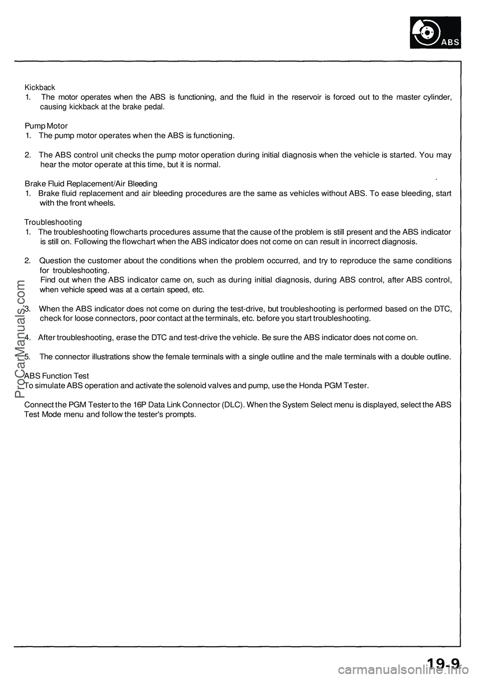
Kickback
1. The motor operates when the ABS is functioning, and the fluid in the reservoir is forced out to the master cylinder,
causing kickback at the brake pedal.
Pump Motor
1. The pump motor operates when the ABS is functioning.
2. The ABS control unit checks the pump motor operation during initial diagnosis when the vehicle is started. You may
hear the motor operate at this time, but it is normal.
Brake Fluid Replacement/Air Bleeding
1. Brake fluid replacement and air bleeding procedures are the same as vehicles without ABS. To ease bleeding, start
with the front wheels.
Troubleshooting
1. The troubleshooting flowcharts procedures assume that the cause of the problem is still present and the ABS indicator
is still on. Following the flowchart when the ABS indicator does not come on can result in incorrect diagnosis.
2. Question the customer about the conditions when the problem occurred, and try to reproduce the same conditions
for troubleshooting.
Find out when the ABS indicator came on, such as during initial diagnosis, during ABS control, after ABS control,
when vehicle speed was at a certain speed, etc.
3. When the ABS indicator does not come on during the test-drive, but troubleshooting is performed based on the DTC,
check for loose connectors, poor contact at the terminals, etc. before you start troubleshooting.
4. After troubleshooting, erase the DTC and test-drive the vehicle. Be sure the ABS indicator does not come on.
5. The connector illustrations show the female terminals with a single outline and the male terminals with a double outline.
ABS Function Test
To simulate ABS operation and activate the solenoid valves and pump, use the Honda PGM Tester.
Connect the PGM Tester to the 16P Data Link Connector (DLC). When the System Select menu is displayed, select the ABS
Test Mode menu and follow the tester's prompts.ProCarManuals.com
Page 182 of 1503
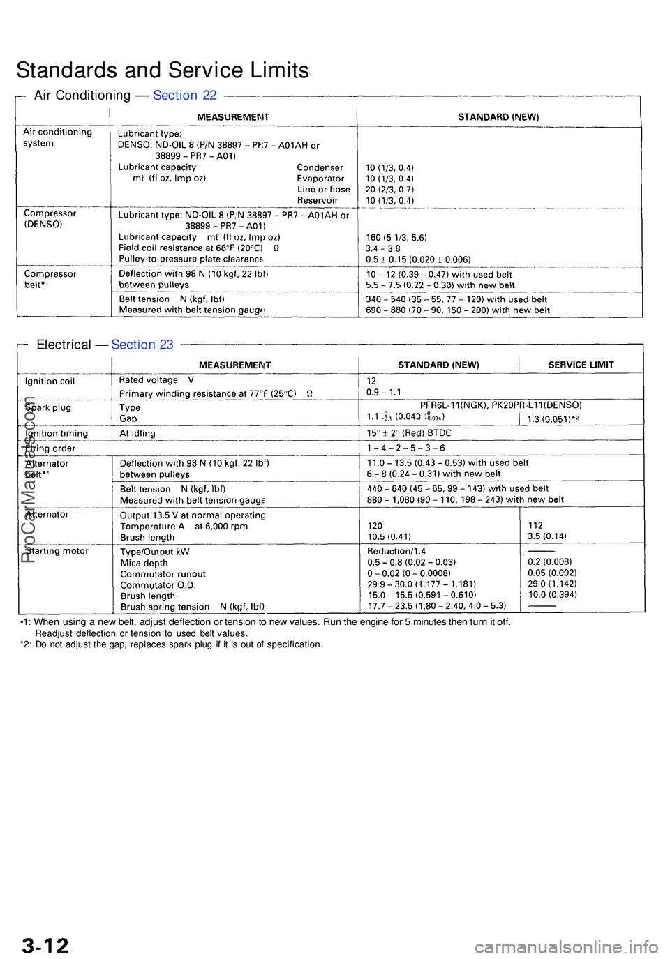
Standards an d Servic e Limit s
Air Conditionin g — Sectio n 2 2
Electrica l — Sectio n 2 3
•1 : Whe n usin g a ne w belt , adjus t deflectio n o r tensio n to ne w values . Ru n th e engin e fo r 5 minute s the n tur n it off .Readjus t deflectio n o r tensio n t o use d bel t values .
*2 : D o no t adjus t th e gap , replace s spar k plu g i f i t i s ou t o f specification .
ProCarManuals.com
Page 210 of 1503
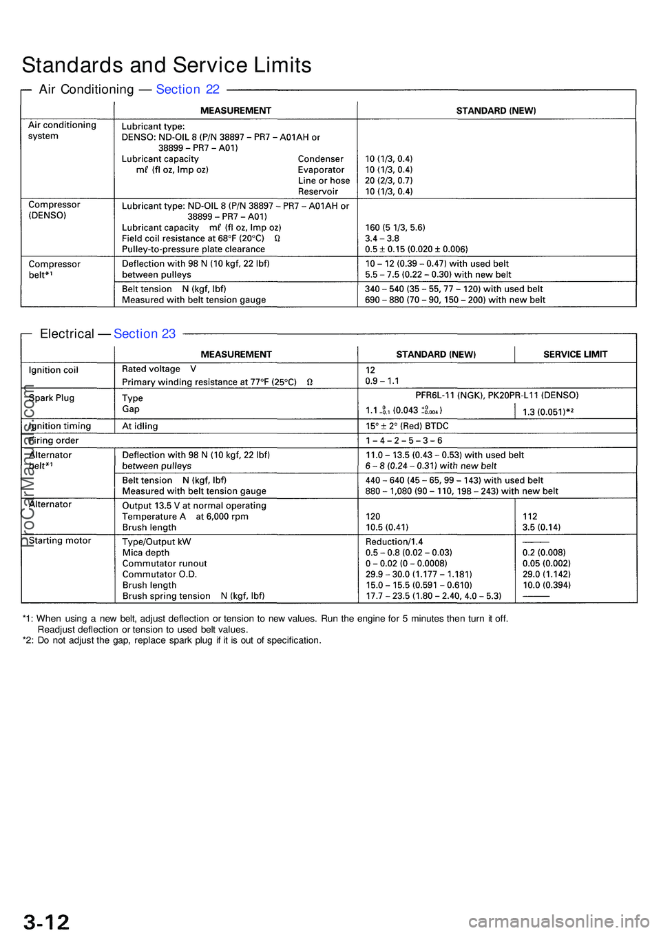
Standards an d Servic e Limit s
Air Conditionin g — Sectio n 2 2
Electrica l — Sectio n 2 3
*1 : Whe n usin g a ne w belt , adjus t deflectio n o r tensio n t o ne w values . Run the engin e fo r 5 minute s the n tur n i t off .
Readjus t deflectio n o r tensio n t o use d bel t values .
*2 : D o no t adjus t th e gap , replac e spar k plu g i f i t i s ou t o f specification .
ProCarManuals.com
Page 310 of 1503
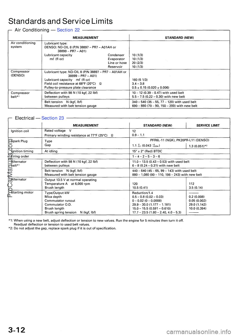
Standards an d Servic e Limit s
Air Conditionin g — Sectio n 2 2
Electrica l — Sectio n 2 3
ProCarManuals.com
Page 330 of 1503
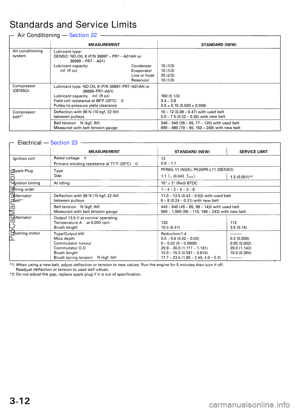
Standards an d Servic e Limit s
Air Conditionin g — Sectio n 2 2
Electrica l — Sectio n 2 3
ProCarManuals.com
Page 369 of 1503
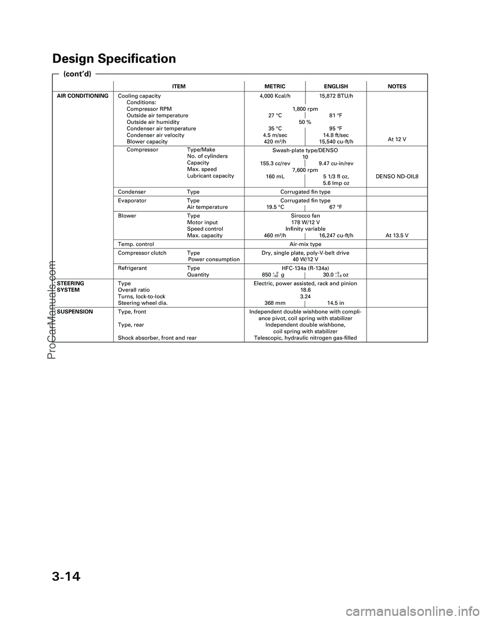
3-14
Design Specification
ITEMMETRICENGLISH
AIR CONDITIONINGCooling capacity
Conditions:
Compressor RPM
Outside air temperature
Outside air humidity
Condenser air temperature
Condenser air velocity
Blower capacity4,000 Kcal/h 15,872 BTU/h
1,800 rpm
27 °C 81 °F
50 %
35 °C 95 °F
4.5 m/sec 14.8 ft/sec
420 m
3/h 15,540 cu-ft/h
Independent double wishbone with compli-
ance pivot, coil spring with stabilizer
Independent double wishbone,
coil spring with stabilizer
Telescopic, hydraulic nitrogen gas-filledSUSPENSIONType, front
Type, rear
Shock absorber, front and rear
Evaporator Type
Air temperatureCorrugated fin type
19.5 °C 67 °F
Compressor Type/Make
No. of cylinders
Capacity
Max. speed
Lubricant capacity
NOTES
Swash-plate type/DENSO
10
155.3 cc/rev 9.47 cu-in/rev
7,600 rpm
160 mL 5 1/3 fl oz,
5.6 lmp oz
At 12 V
Air-mix type
Sirocco fan
178 W/12 V
Infinity variable
460 m
3/h 16,247 cu-ft/h
DENSO ND-OIL8
Condenser TypeCorrugated fin type
Temp. control
Blower Type
Motor input
Speed control
Max. capacity
At 13.5 V
Refrigerant Type
Quantity
Dry, single plate, poly-V-belt drive
40 W/12 VCompressor clutch Type
Power consumption
Electric, power assisted, rack and pinion
18.6
3.24
368 mm 14.5 inSTEERING
SYSTEMType
Overall ratio
Turns, lock-to-lock
Steering wheel dia.
HFC-134a (R-134a)
850+0g 30.0+0oz–50–1.8
(cont’d)
*04-NSX (61SW004)SEC03(01-16) 9/22/04 1:49 PM Page 3-14
ProCarManuals.com