power steering ACURA NSX 1997 Service Repair Manual
[x] Cancel search | Manufacturer: ACURA, Model Year: 1997, Model line: NSX, Model: ACURA NSX 1997Pages: 1503, PDF Size: 57.08 MB
Page 369 of 1503
3-14
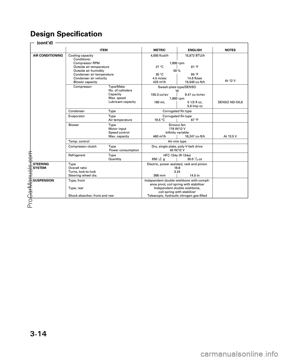
Design Specification
ITEMMETRICENGLISH
AIR CONDITIONINGCooling capacity
Conditions:
Compressor RPM
Outside air temperature
Outside air humidity
Condenser air temperature
Condenser air velocity
Blower capacity4,000 Kcal/h 15,872 BTU/h
1,800 rpm
27 °C 81 °F
50 %
35 °C 95 °F
4.5 m/sec 14.8 ft/sec
420 m
3/h 15,540 cu-ft/h
Independent double wishbone with compli-
ance pivot, coil spring with stabilizer
Independent double wishbone,
coil spring with stabilizer
Telescopic, hydraulic nitrogen gas-filledSUSPENSIONType, front
Type, rear
Shock absorber, front and rear
Evaporator Type
Air temperatureCorrugated fin type
19.5 °C 67 °F
Compressor Type/Make
No. of cylinders
Capacity
Max. speed
Lubricant capacity
NOTES
Swash-plate type/DENSO
10
155.3 cc/rev 9.47 cu-in/rev
7,600 rpm
160 mL 5 1/3 fl oz,
5.6 lmp oz
At 12 V
Air-mix type
Sirocco fan
178 W/12 V
Infinity variable
460 m
3/h 16,247 cu-ft/h
DENSO ND-OIL8
Condenser TypeCorrugated fin type
Temp. control
Blower Type
Motor input
Speed control
Max. capacity
At 13.5 V
Refrigerant Type
Quantity
Dry, single plate, poly-V-belt drive
40 W/12 VCompressor clutch Type
Power consumption
Electric, power assisted, rack and pinion
18.6
3.24
368 mm 14.5 inSTEERING
SYSTEMType
Overall ratio
Turns, lock-to-lock
Steering wheel dia.
HFC-134a (R-134a)
850+0g 30.0+0oz–50–1.8
(cont’d)
*04-NSX (61SW004)SEC03(01-16) 9/22/04 1:49 PM Page 3-14
ProCarManuals.com
Page 371 of 1503
4-2
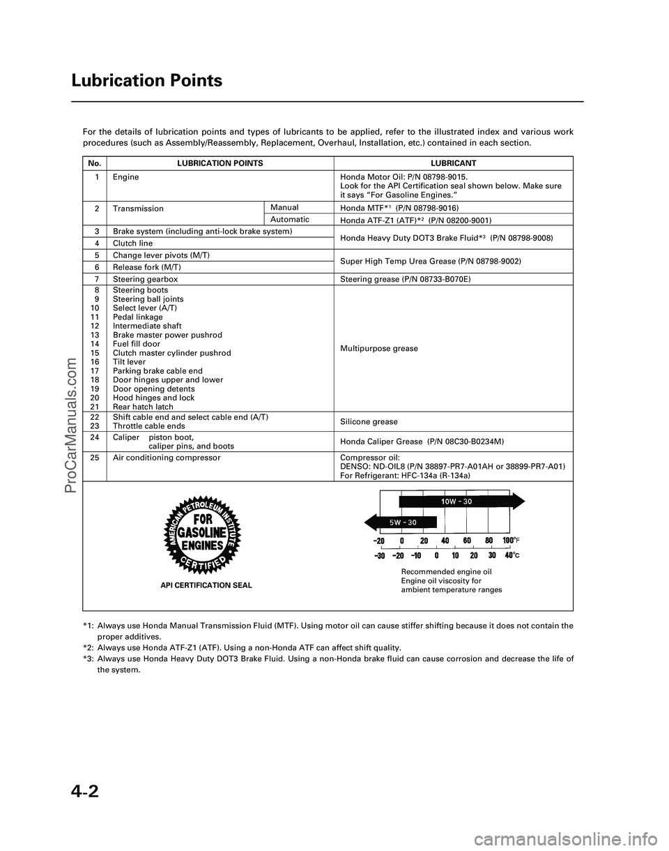
For the details of lubrication points and types of lubricants to be appl\
ied, refer to the illustrated index and various work
procedures (such as Assembly/Reassembly, Replacement, Overhaul, Install\
ation, etc.) contained in each section.
*1: Always use Honda Manual Transmission Fluid (MTF). Using motor oil can \
cause stiffer shifting because it does not contain theproper additives.
*2: Always use Honda ATF-Z1 (ATF). Using a non-Honda ATF can affect shift \
quality.
*3: Always use Honda Heavy Duty DOT3 Brake Fluid. Using a non-Honda brake fl\
uid can cause corrosion and decrease the life of the system.
Lubrication Points
No.LUBRICATION POINTSLUBRICANT
1Honda Motor Oil: P/N 08798-9015.
Look for the API Certification seal shown below. Make sure
it says “For Gasoline Engines.”
2TransmissionHonda MTF*1(P/N 08798-9016)
3Brake system (including anti-lock brake system)Honda Heavy Duty DOT3 Brake Fluid*3(P/N 08798-9008)4Clutch line
5Change lever pivots (M/T)Super High Temp Urea Grease (P/N 08798-9002)6Release fork (M/T)
8
9
10
11
12
13
14
15
16
17
18
19
20
21Steering boots
Steering ball joints
Select lever (A/T)
Pedal linkage
Intermediate shaft
Brake master power pushrod
Fuel fill door
Clutch master cylinder pushrod
Tilt lever
Parking brake cable end
Door hinges upper and lower
Door opening detents
Hood hinges and lock
Rear hatch latch
Multipurpose grease
24
22
23
Caliper piston boot, caliper pins, and boots
Shift cable end and select cable end (A/T)
Throttle cable ends
Honda Caliper Grease (P/N 08C30-B0234M)
Silicone grease
25Air conditioning compressorCompressor oil:
DENSO: ND-OIL8 (P/N 38897-PR7-A01AH or 38899-PR7-A01)
For Refrigerant: HFC-134a (R-134a)
Manual
Honda ATF-Z1 (ATF)*2(P/N 08200-9001)Automatic
7Steering gearboxSteering grease (P/N 08733-B070E)
Engine
API CERTIFICATION SEAL
Recommended engine oil
Engine oil viscosity for
ambient temperature ranges
*05-NSX (61SW004)SEC04(01-10) 9/22/04 1:49 PM Page 4-2
ProCarManuals.com
Page 896 of 1503
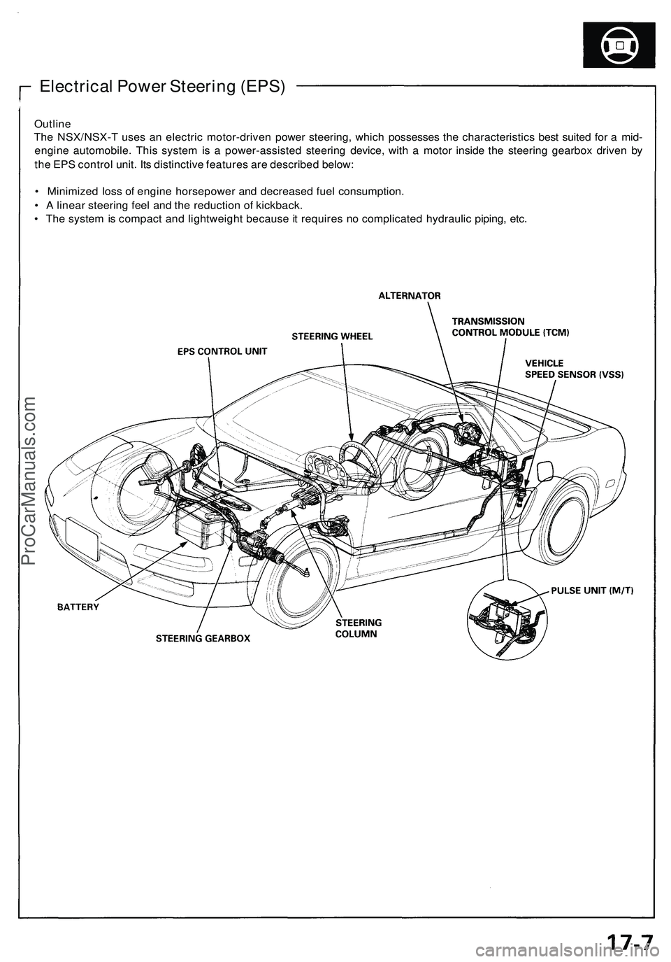
Electrical Powe r Steerin g (EPS )
Outlin e
The NSX/NSX- T use s a n electri c motor-drive n powe r steering , whic h possesse s th e characteristic s bes t suite d fo r a mid -
engin e automobile . Thi s syste m is a power-assiste d steerin g device , wit h a moto r insid e th e steerin g gearbo x drive n b y
th e EP S contro l unit . It s distinctiv e feature s ar e describe d below :
• Minimize d los s o f engin e horsepowe r an d decrease d fue l consumption .
• A linea r steerin g fee l an d th e reductio n o f kickback .
• Th e syste m is compac t an d lightweigh t becaus e it require s n o complicate d hydrauli c piping , etc .
ProCarManuals.com
Page 902 of 1503
Self-Diagnosis Function
The EPS control unit monitors the system inputs and outputs, and the driving current of the motor. If there is a problem in
the system, the control unit turns the system off by actuating the relay. Power assist stops and normal manual steering
operation resumes. The control unit also turns the EPS indicator light on to alert the driver, and memorizes the problem in
the form of a code. Connecting the terminals of the service check connector with the SCS service connector (special tool)
enables the EPS indicator light to blink the problem code when the ignition switch is turned on (II).
Unloader Control
If the steering wheel is turned fully and held in the full-lock position, the steering torque reaches the maximum point, and
an over-current flows to the motor. The control unit detects this and reduces the current flow to the motor.
Average Moving Current Control
The electric current flow to the motor is estimated from the current values detected by the current sensor, and the average
current is obtained at two second intervals. The motor driving current is suppressed when the average current value
exceeds a predetermined marginal value. The control unit regulates the motor current during continuous loading to sup-
press any excessive temperature rise in the motor.ProCarManuals.com
Page 903 of 1503
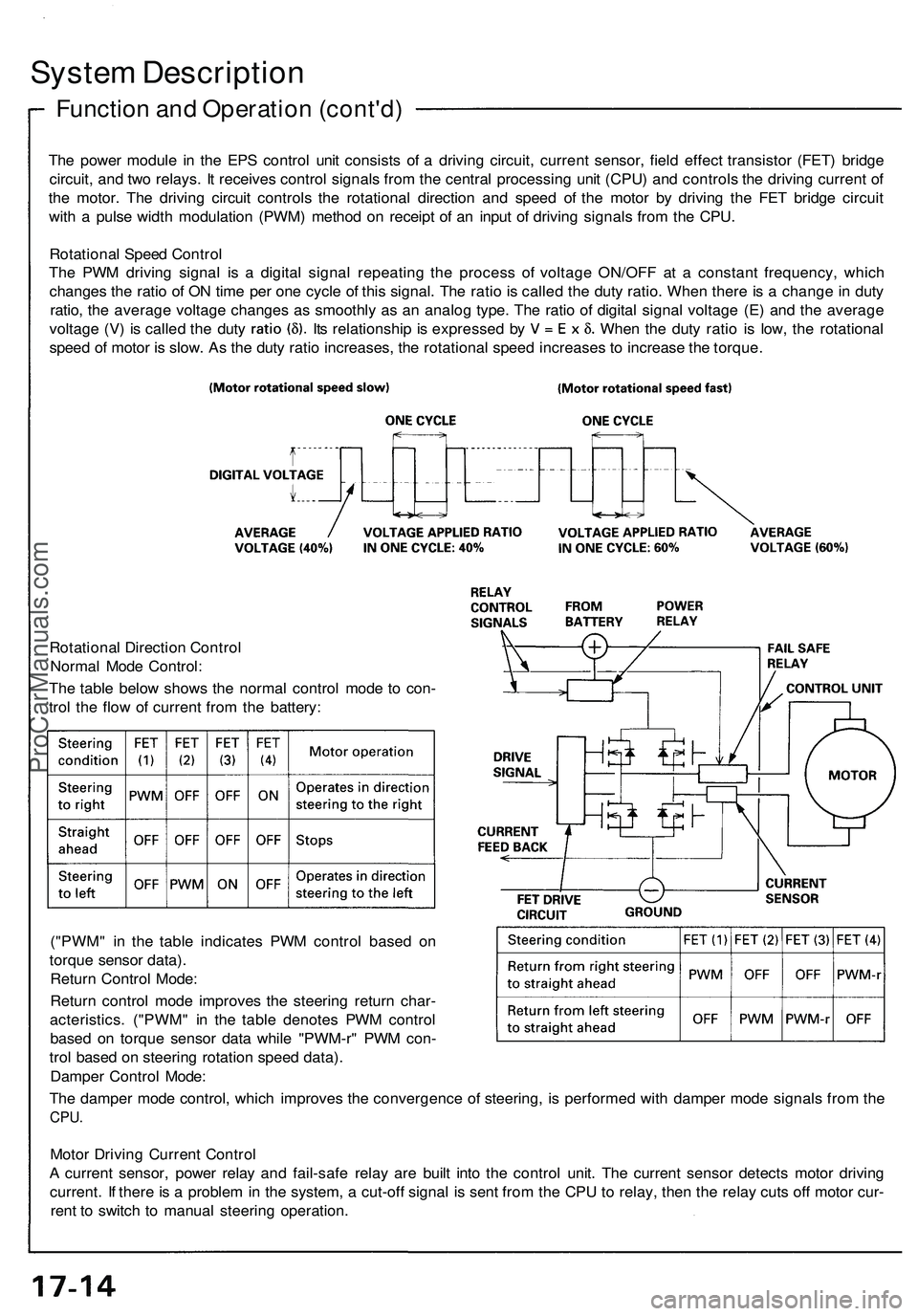
System Description
Function and Operation (cont'd)
The power module in the EPS control unit consists of a driving circuit, current sensor, field effect transistor (FET) bridge
circuit, and two relays. It receives control signals from the central processing unit (CPU) and controls the driving current of
the motor. The driving circuit controls the rotational direction and speed of the motor by driving the FET bridge circuit
with a pulse width modulation (PWM) method on receipt of an input of driving signals from the CPU.
Rotational Speed Control
The PWM driving signal is a digital signal repeating the process of voltage ON/OFF at a constant frequency, which
changes the ratio of ON time per one cycle of this signal. The ratio is called the duty ratio. When there is a change in duty
ratio, the average voltage changes as smoothly as an analog type. The ratio of digital signal voltage (E) and the average
voltage (V) is called the duty Its relationship is expressed by When the duty ratio is low, the rotational
speed of motor is slow. As the duty ratio increases, the rotational speed increases to increase the torque.
Rotational Direction Control
Normal Mode Control:
The table below shows the normal control mode to con-
trol the flow of current from the battery:
("PWM" in the table indicates PWM control based on
torque sensor data).
Return Control Mode:
Return control mode improves the steering return char-
acteristics. ("PWM" in the table denotes PWM control
based on torque sensor data while "PWM-r" PWM con-
trol based on steering rotation speed data).
Damper Control Mode:
The damper mode control, which improves the convergence of steering, is performed with damper mode signals from the
CPU.
Motor Driving Current Control
A current sensor, power relay and fail-safe relay are built into the control unit. The current sensor detects motor driving
current. If there is a problem in the system, a cut-off signal is sent from the CPU to relay, then the relay cuts off motor cur-
rent to switch to manual steering operation.ProCarManuals.com
Page 904 of 1503
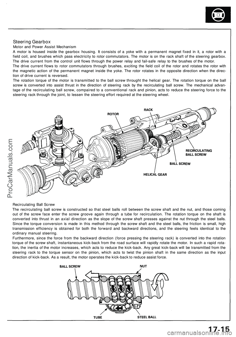
Steering Gearbox
Motor and Power Assist Mechanism
A motor is housed inside the gearbox housing. It consists of a yoke with a permanent magnet fixed in it, a rotor with a
field coil, and brushes which pass electricity to rotor commutators. The motor is on the rack shaft of the steering gearbox.
The drive current from the control unit flows through the power relay and fail-safe relay to the brushes of the motor.
The drive current flows to rotor commutators through brushes, exciting the field coil of the rotor and rotates the rotor with
the magnetic action of the permanent magnet inside the yoke. The rotor rotates in the opposite direction when the direc-
tion of drive current is reversed.
The rotation torque of the motor is transmitted to the ball screw throught the helical gear. The rotation torque on the ball
screw is converted into assist thrust in the direction of steering rack by the recirculating ball screw. The mechanical advan-
tage of the recirculating ball screw, compaired to a conventional rack and pinion, acts to reduce the steering force to the
steering rack through the joint, to lessen the steering effort required at the steering wheel.
Recirculating Ball Screw
The recirculating ball screw is constructed so that steel balls roll between the screw shaft and the nut, and those coming
out of the screw face enter the screw groove again through a tube for recirculation. The rotation torque on the shaft is
converted into thrust in an axial direction as the slope of the screw shaft presses against the nut through the steel balls.
Since the torque conversion is made in this method through the screw shaft and the steel balls, the friction is small, high
transmission efficiency is obtained for both the forward and backward directions, and the steering feels identical to the
ordinary manual steering.
Furthermore, since the force from the backward direction (force pressing the steering rack) is converted into the rotation
torque of the screw shaft, instantaneous kick-back from the road surface will rapidly rotate the motor. In such a rapid rota-
tion, the inertia of the motor increases, which acts to reduce the kick-back. Any great kick-back will be transmitted from the
steering rack to the torque sensor on the pinion, which acts to twist the pinion shaft in the same direction as the input
direction of kick-back. As a result, the motor operates the kick-back to reduce assist force.ProCarManuals.com
Page 909 of 1503
Troubleshooting Precautions
EPS Indicator Light
Under normal conditions, the EPS indicator light in the gauge assembly comes on when the ignition switch is turned to
the ON (II) position, then goes off after the engine is started. This indicates that the bulb and its circuits are operating cor-
rectly. If there is any trouble in the system, the EPS indicator light turns on during driving, and the power steering assist is
turned off. When the EPS indicator light comes on, the control unit memorizes the DTC. In this case, the control unit does
not activate the EPS system after the engine starts again but it keeps the EPS indicator light on.
Diagnostic Trouble Code (DTC)
• The lowest DTC is indicated first.
• The DTCs continue blinking until the ignition switch is turned off.
• The DTCs are erased from the control unit when the EPS control unit VBU power supply or connector is disconnected.
• The EPS system can be reset and the control unit's memory can be erased by disconnecting the CLOCK (7.5 A) fuse for
more than ten seconds.
Self-diagnosis:
The CPU (central processing unit) controls the following when it detects a problem during self-diagnosis:
1. Turns the EPS indicator light ON to alert the driver.
2. Power assist stops, and normal manual steering operation resumes (except DTC 33).
3. The EPS control unit memorizes the diagnostic trouble code (DTC).
4. After the DTC is stored in the control unit, the CPU stops self-diagnosis.
Troubleshooting:
• Before starting the troubleshooting, clear the DTC by disconnecting the CLOCK (7.5 A) fuse for ten seconds or more,
and test-drive the car. Check that the symptom of the trouble appears again, and then troubleshoot.
• When both EPS indicator light and A/T "D" indicator light come on, perform the A/T troubleshooting first.
• When the customer's reported problem cannot be verified in the car, ask the customer about the conditions when the
EPS indicator light came ON, then test-drive the car under those conditions, if possible. If the EPS indicator light does
not come ON during the test, check for loose connections or poor contacts at the connectors by wiggling the harness,
etc.
• The connector terminal numbers are viewed from the wire side for the female terminals and from the terminal side for
the male terminals.
• After the repair, test-drive the car and check that the EPS indicator light does not come ON again during the test. (Refer
to the Symptom-to-System Chart for diagnostic period.)ProCarManuals.com
Page 913 of 1503
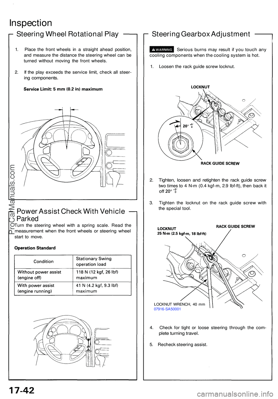
Inspection
Steering Whee l Rotationa l Pla y
1. Plac e th e fron t wheel s i n a straigh t ahea d position ,
an d measur e th e distanc e th e steerin g whee l ca n b e
turne d withou t movin g th e fron t wheels .
2 . I f th e pla y exceed s th e servic e limit , chec k al l steer -
ing components .
Power Assis t Chec k Wit h Vehicl e
Parked
Turn th e steerin g whee l wit h a sprin g scale . Rea d th e
measuremen t whe n th e fron t wheel s o r steerin g whee l
start t o move .
Steerin g Gearbo x Adjustmen t
1. Loose n th e rac k guid e scre w locknut .
Seriou
s burn s ma y resul t i f yo u touc h an y
coolin g component s whe n th e coolin g syste m is hot .
2. Tighten , loose n an d retighte n th e rac k guid e scre w
two time s t o 4 N- m (0. 4 kgf-m , 2. 9 Ibf-ft) , the n bac k i t
of f
3. Tighte n th e locknu t o n th e rac k guid e scre w wit h
th e specia l tool .
4 . Chec k fo r tigh t o r loos e steerin g throug h th e com -
plete turnin g travel .
5. Rechec k steerin g assist .
LOCKNU T WRENCH , 4 0 m m
0791 6-SA5000 1
ProCarManuals.com
Page 1045 of 1503
Outline
System Description
Role of System
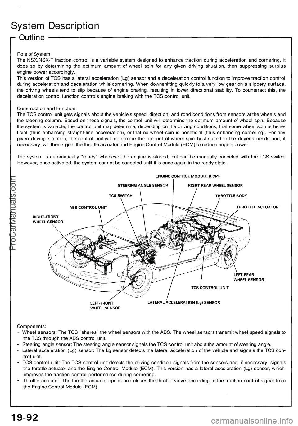
The NSX/NSX-T traction control is a variable system designed to enhance traction during acceleration and cornering. It
does so by determining the optimum amount of wheel spin for any given driving situation, then suppressing surplus
engine power accordingly.
This version of TCS has a lateral acceleration (Lg) sensor and a deceleration control function to improve traction control
during acceleration and deceleration while cornering. When downshifting quickly to a very low gear on a slippery surface,
the driving wheels tend to slip because of engine braking, resulting in lower directional stability. To counteract this, the
deceleration control function controls engine braking with the TCS control unit.
Construction and Function
The TCS control unit gets signals about the vehicle's speed, direction, and road conditions from sensors at the wheels and
the steering column. Based on these signals, the control unit will determine the optimum amount of wheel spin. Because
the system is variable, the control unit may determine, depending on the driving conditions, that some wheel spin is bene-
ficial (thus enhancing straight-line acceleration), or that no wheel spin is beneficial (thus enhancing cornering). For any
given driving situation, the control unit will determine the amount of wheel spin best suited to the driver's needs and, if
necessary, will then signal the throttle actuator and Engine Control Module (ECM) to reduce engine power.
The system is automatically "ready" whenever the engine is started, but can be manually canceled with the TCS switch.
However, once activated, the system cannot be canceled until it is once again in the ready state.
Components:
• Wheel sensors: The TCS "shares" the wheel sensors with the ABS. The wheel sensors transmit wheel speed signals to
the TCS through the ABS control unit.
• Steering angle sensor: The steering angle sensor signals the TCS control unit about the amount of steering angle.
• Lateral acceleration (Lg) sensor: The Lg sensor detects the lateral acceleration of the vehicle and signals the TCS con-
trol unit.
• TCS control unit: The TCS control unit detects the driving condition signals from the sensors and, if necessary, signals
the throttle actuator and the Engine Control Module (ECM). This version has a lateral acceleration (Lg) sensor, which
improves the traction control performance during cornering.
• Throttle actuator: The throttle actuator opens and closes the throttle valve according to the traction control signal from
the Engine Control Module (ECM).ProCarManuals.com
Page 1046 of 1503
Construction and Function
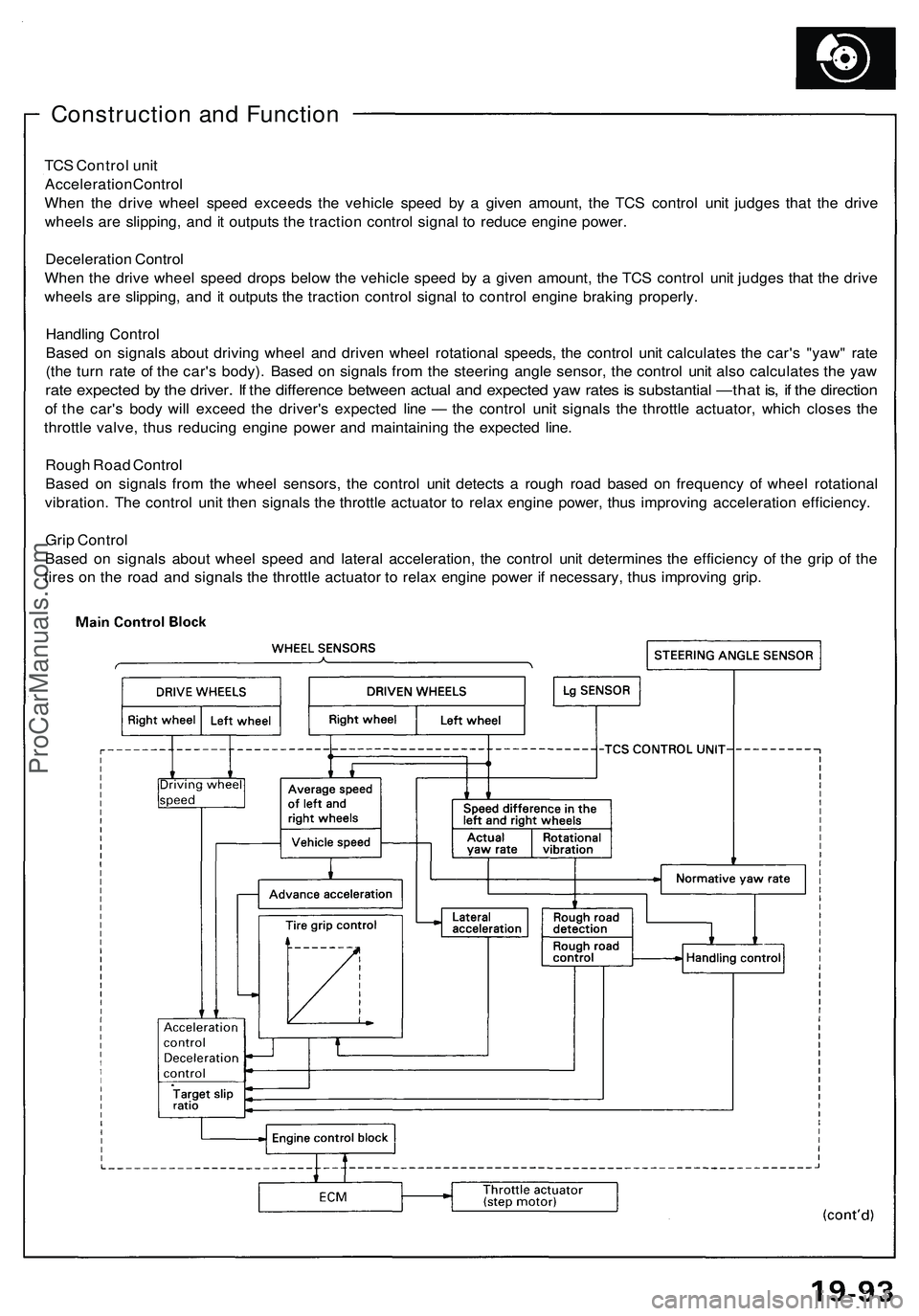
TCS Control unit
Acceleration Control
When the drive wheel speed exceeds the vehicle speed by a given amount, the TCS control unit judges that the drive
wheels are slipping, and it outputs the traction control signal to reduce engine power.
Deceleration Control
When the drive wheel speed drops below the vehicle speed by a given amount, the TCS control unit judges that the drive
wheels are slipping, and it outputs the traction control signal to control engine braking properly.
Handling Control
Based on signals about driving wheel and driven wheel rotational speeds, the control unit calculates the car's "yaw" rate
(the turn rate of the car's body). Based on signals from the steering angle sensor, the control unit also calculates the yaw
rate expected by the driver. If the difference between actual and expected yaw rates is substantial —that is, if the direction
of the car's body will exceed the driver's expected line — the control unit signals the throttle actuator, which closes the
throttle valve, thus reducing engine power and maintaining the expected line.
Rough Road Control
Based on signals from the wheel sensors, the control unit detects a rough road based on frequency of wheel rotational
vibration. The control unit then signals the throttle actuator to relax engine power, thus improving acceleration efficiency.
Grip Control
Based on signals about wheel speed and lateral acceleration, the control unit determines the efficiency of the grip of the
tires on the road and signals the throttle actuator to relax engine power if necessary, thus improving grip.ProCarManuals.com