clutch ACURA NSX 1997 Service Repair Manual
[x] Cancel search | Manufacturer: ACURA, Model Year: 1997, Model line: NSX, Model: ACURA NSX 1997Pages: 1503, PDF Size: 57.08 MB
Page 10 of 1503
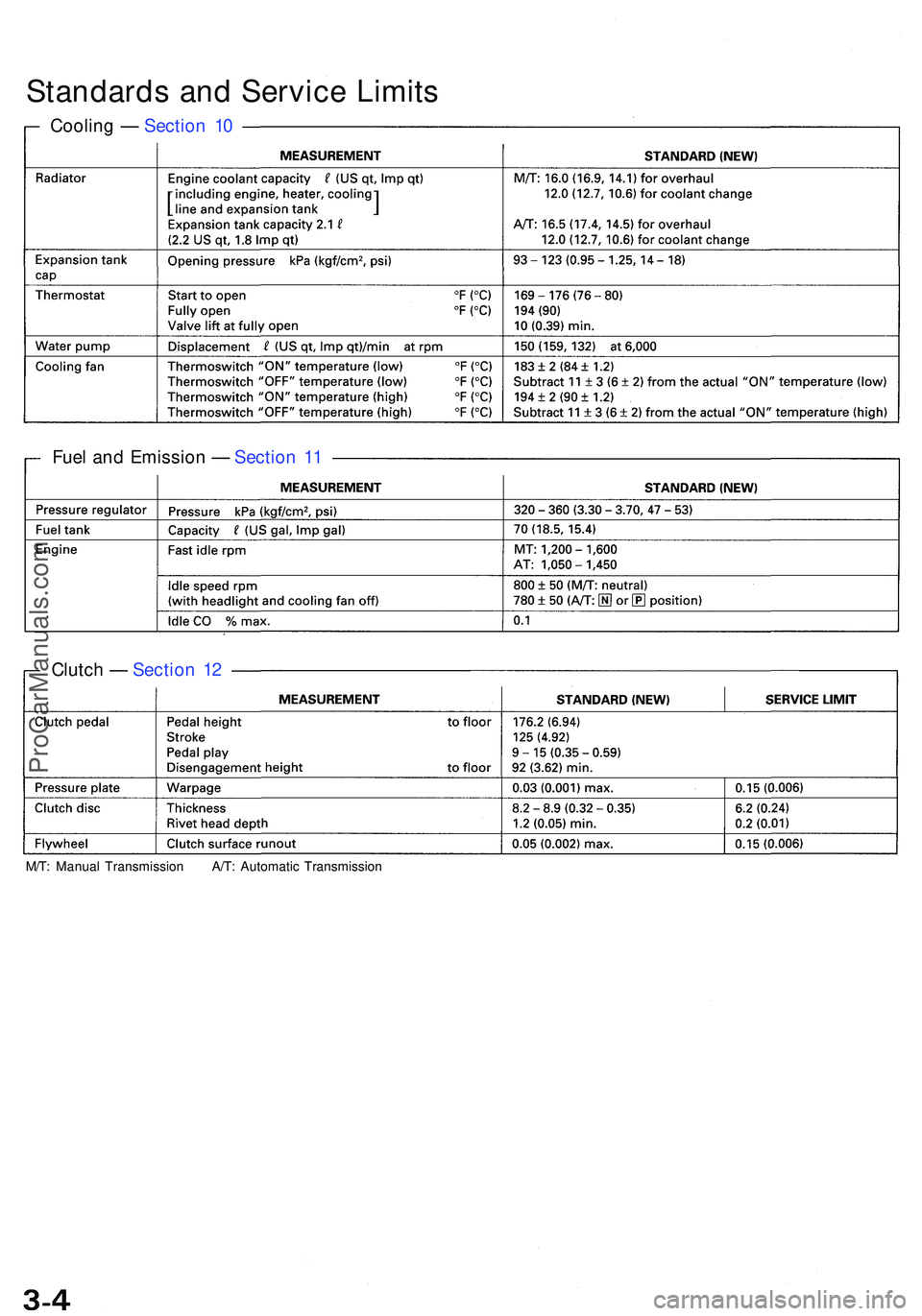
M/T: Manua l Transmissio n A/T : Automati c Transmissio n
Clutch — Sectio n 1 2
Fue
l an d Emissio n — Sectio n 1 1
Coolin
g — Sectio n 1 0
Standard s an d Servic e Limit s
ProCarManuals.com
Page 161 of 1503
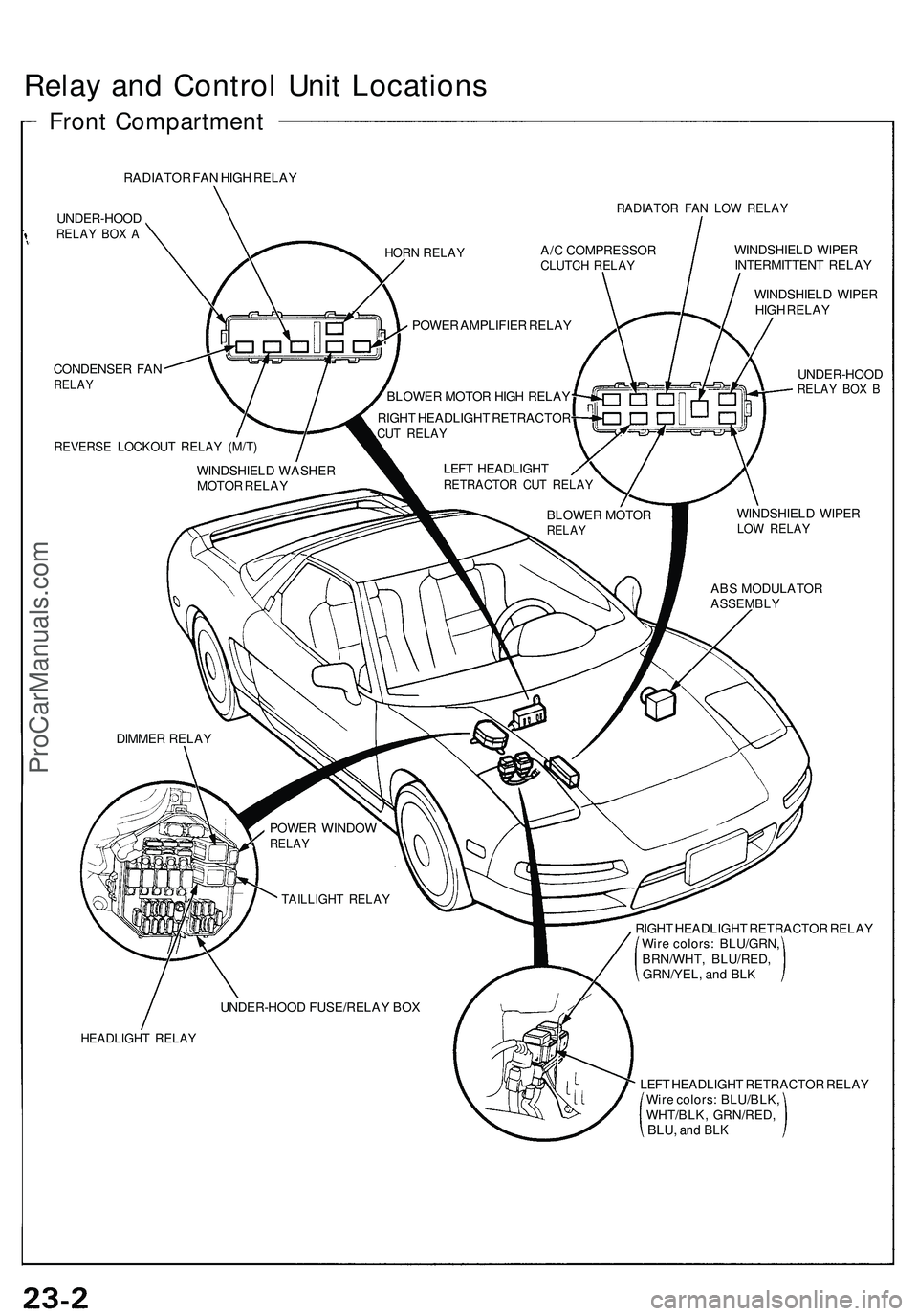
Relay an d Contro l Uni t Location s
Front Compartmen t
RADIATOR FA N HIG H RELA Y
UNDER-HOO D
RELAY BO X A
RADIATO R FA N LO W RELA Y
CONDENSE R FA NRELA Y
REVERS E LOCKOU T RELA Y (M/T )
WINDSHIEL D WIPE R
INTERMITTEN T RELA Y
WINDSHIEL D WIPE R
HIG H RELA Y
UNDER-HOO D
RELAY BO X B
WINDSHIEL D WIPE RLOW RELA Y
RIGHT HEADLIGH T RETRACTO R RELA Y
Wir e colors : BLU/GRN ,
BRN/WHT , BLU/RED ,
GRN/YEL , an d BL K
HEADLIGH T RELA Y
LEFT HEADLIGH T RETRACTO R RELA Y
Wir e colors : BLU/BLK ,
WHT/BLK , GRN/RED ,
BLU, and BL K
HOR N RELA YA/C COMPRESSO RCLUTCH RELA Y
POWER AMPLIFIE R RELA Y
BLOWE R MOTO R HIG H RELA Y
RIGH T HEADLIGH T RETRACTO R
CUT RELA Y
LEFT HEADLIGH TRETRACTO R CU T RELA Y
BLOWE R MOTO RRELAY
ABS MODULATO RASSEMBLY
WINDSHIEL D WASHE R
MOTO R RELA Y
DIMME R RELA Y
POWER WINDO W
RELAY
TAILLIGH T RELA Y
UNDER-HOO D FUSE/RELA Y BO X
ProCarManuals.com
Page 176 of 1503
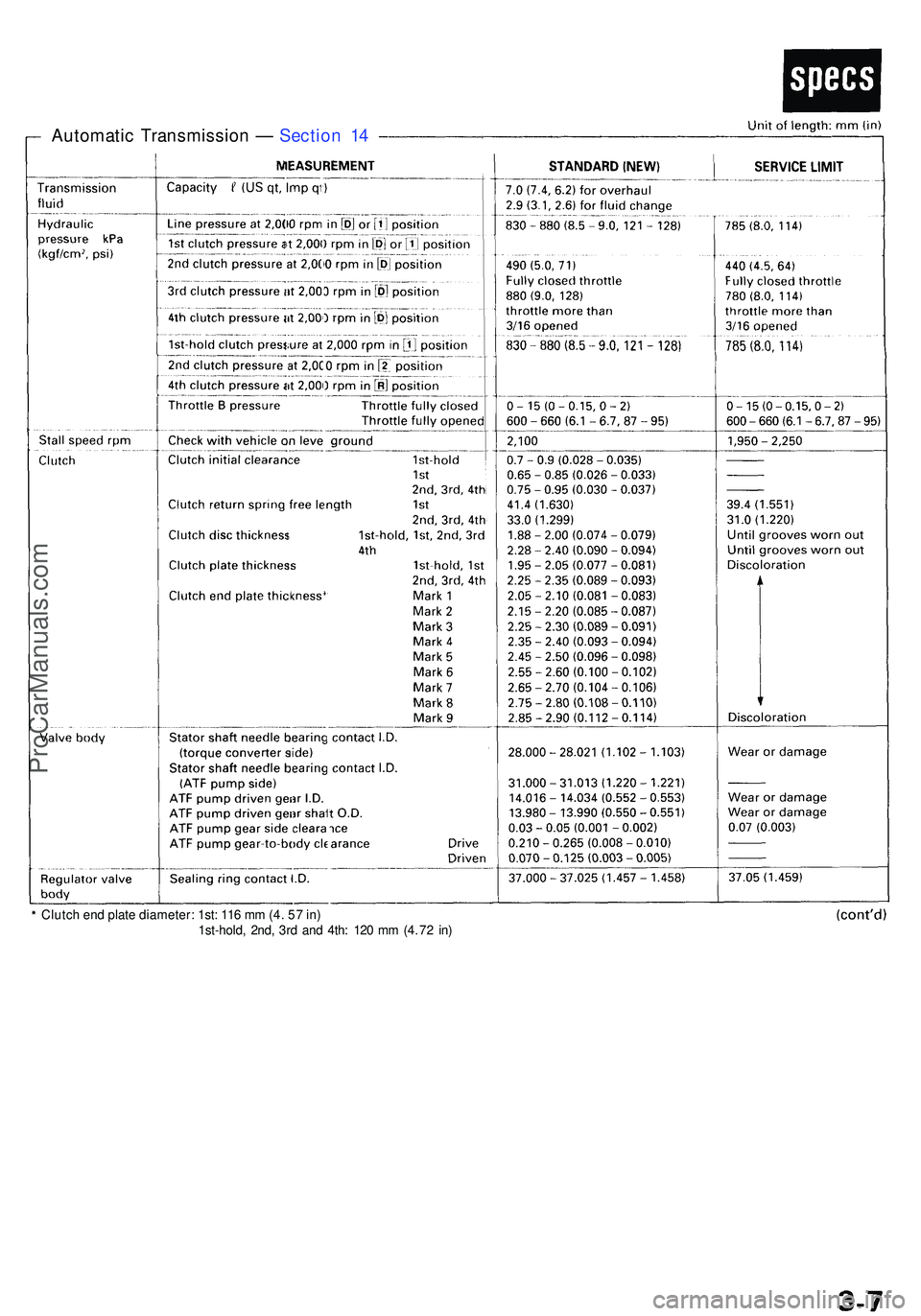
Clutch en d plat e diameter : 1st : 11 6 m m (4 . 5 7 in )
1st-hold , 2nd , 3r d an d 4th : 12 0 m m (4 . 7 2 in )
Automati c Transmissio n — Sectio n 1 4
ProCarManuals.com
Page 343 of 1503
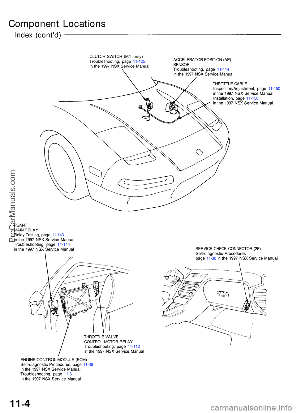
Component Location s
Index (cont'd )
CLUTCH SWITC H (M/ T only )Troubleshooting , pag e 11-12 5in th e 199 7 NS X Servic e Manua l
ACCELERATO R POSITIO N (AP )SENSO RTroubleshooting , pag e 11-11 4in th e 199 7 NS X Servic e Manua l
THROTTL E CABL EInspection/Adjustment , pag e 11-15 0in th e 199 7 NS X Servic e Manua lInstallation , pag e 11-15 0in th e 199 7 NS X Servic e Manua l
PGM-FIMAIN RELA YRelay Testing , pag e 11-14 3in th e 199 7 NS X Servic e Manua lTroubleshooting , pag e 11-14 4in th e 199 7 NS X Servic e Manua lSERVIC E CHEC K CONNECTO R (2P )Self-diagnosti c Procedure spage 11-3 8 in th e 199 7 NS X Servic e Manua l
THROTTL E VALV ECONTRO L MOTO R RELA YTroubleshooting , pag e 11-11 2in th e 199 7 NS X Servic e Manua l
ENGINE CONTRO L MODUL E (ECM )Self-diagnosti c Procedures , pag e 11-3 8in th e 199 7 NS X Servic e Manua lTroubleshooting , pag e 11-6 1in th e 199 7 NS X Servic e Manua l
ProCarManuals.com
Page 368 of 1503
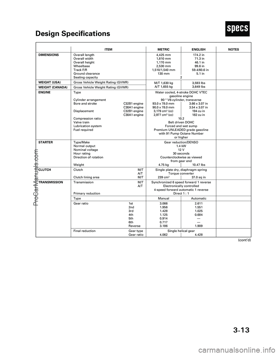
3-13
TDesign Specifications
(cont’d)
ITEMMETRICENGLISH
DIMENSIONSOverall length
Overall width
Overall height
Wheelbase
Track F/R
Ground clearance
Seating capacity4,425 mm 174.2 in
1,810 mm 71.3 in
1,170 mm 46.1 in
2,530 mm 99.6 in
1,510/1,540 mm 59.4/60.6 in
130 mm 5.1 in
2
WEIGHT (USA)
Single plate dry, diaphragm spring
Torque converter
239 cm
237.0 sq in
CLUTCHClutch M/T
A/T
Clutch lining area M/T
Gross Vehicle Weight Rating (GVWR)
NOTES
Gear reduction/DENSO
1.4 kW
12 V
30 seconds
Counterclockwise as viewed
from gear end
4.75 kg 10.47 lbs
ENGINEWater cooled, 4-stroke DOHC VTEC
gasoline engine
90 °V6-cylinder, transverse
93.0 x 78.0 mm 3.66 x 3.07 in
90.0 x 78.0 mm 3.54 x 3.07 in
3,179 cm
3(cc) 194 cu in
2,977 cm3(cc) 182 cu in
10.2
Belt driven DOHC
Forced and wet sump
Premium UNLEADED grade gasoline
with 91 Pump Octane Number
or higher
STARTERType/Make
Normal output
Nominal voltage
Hour rating
Direction of rotation
Weight
WEIGHT (CANADA)Gross Vehicle Weight Rating (GVWR)
Synchronized 6 speed forward 1 reverse
Electronically controlled
4-speed forward automatic 1 reverse
Direct 1 : 1Transmission M/T
A/T
Primary reduction
Manual AutomaticType
3.066 2.611
1.956 1.551
1.428 1.025
1.125 0.684
0.914—
0.717—
3.186 1.909Gear ratio 1st
2nd
3rd
4th
5th
6th
Reverse
Single helical gear
4.062 4.428
TRANSMISSION
Final reduction Gear type
Gear ratio
Type
Cylinder arrangement
Bore and strokeC32B1 engine
C30A1 engine
DisplacementC32B1 engine
C30A1 engine
Compression ratio
Valve train
Lubrication system
Fuel required
M/T 1,630 kg 3,593 lbs
A/T 1,655 kg 3,649 lbs
*04-NSX (61SW004)SEC03(01-16) 9/22/04 1:49 PM Page 3-13
ProCarManuals.com
Page 369 of 1503
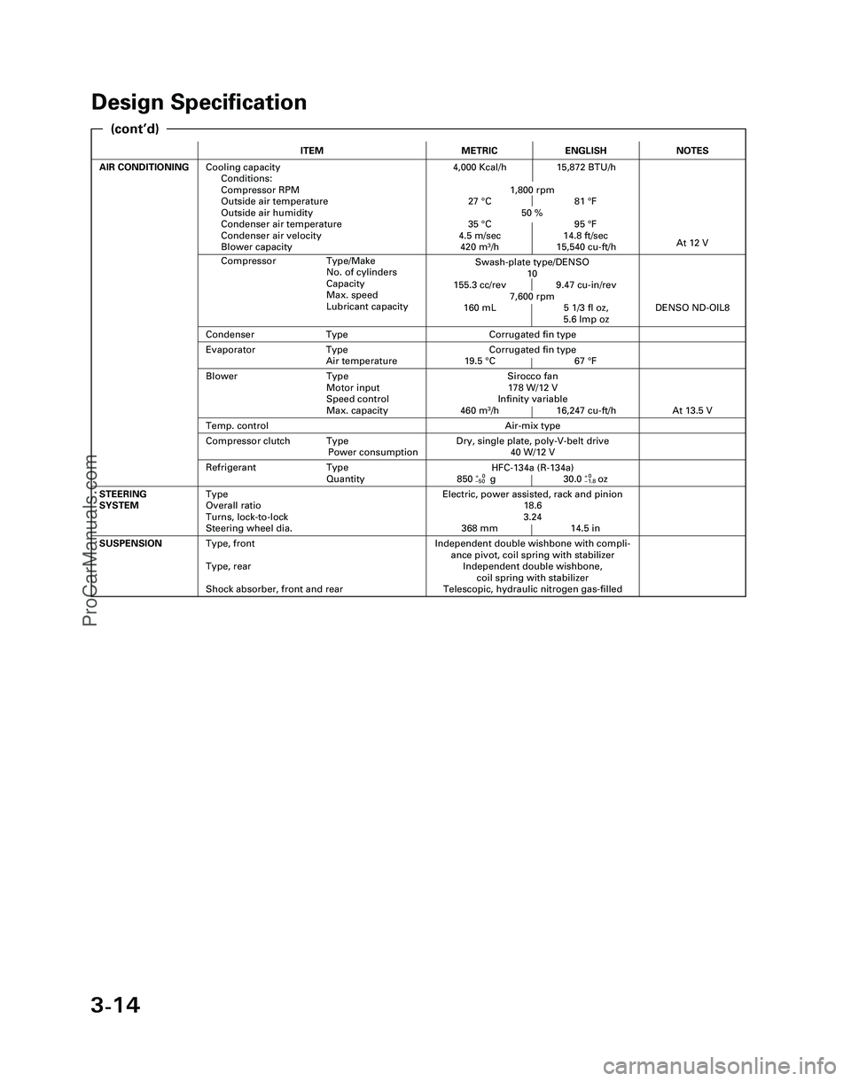
3-14
Design Specification
ITEMMETRICENGLISH
AIR CONDITIONINGCooling capacity
Conditions:
Compressor RPM
Outside air temperature
Outside air humidity
Condenser air temperature
Condenser air velocity
Blower capacity4,000 Kcal/h 15,872 BTU/h
1,800 rpm
27 °C 81 °F
50 %
35 °C 95 °F
4.5 m/sec 14.8 ft/sec
420 m
3/h 15,540 cu-ft/h
Independent double wishbone with compli-
ance pivot, coil spring with stabilizer
Independent double wishbone,
coil spring with stabilizer
Telescopic, hydraulic nitrogen gas-filledSUSPENSIONType, front
Type, rear
Shock absorber, front and rear
Evaporator Type
Air temperatureCorrugated fin type
19.5 °C 67 °F
Compressor Type/Make
No. of cylinders
Capacity
Max. speed
Lubricant capacity
NOTES
Swash-plate type/DENSO
10
155.3 cc/rev 9.47 cu-in/rev
7,600 rpm
160 mL 5 1/3 fl oz,
5.6 lmp oz
At 12 V
Air-mix type
Sirocco fan
178 W/12 V
Infinity variable
460 m
3/h 16,247 cu-ft/h
DENSO ND-OIL8
Condenser TypeCorrugated fin type
Temp. control
Blower Type
Motor input
Speed control
Max. capacity
At 13.5 V
Refrigerant Type
Quantity
Dry, single plate, poly-V-belt drive
40 W/12 VCompressor clutch Type
Power consumption
Electric, power assisted, rack and pinion
18.6
3.24
368 mm 14.5 inSTEERING
SYSTEMType
Overall ratio
Turns, lock-to-lock
Steering wheel dia.
HFC-134a (R-134a)
850+0g 30.0+0oz–50–1.8
(cont’d)
*04-NSX (61SW004)SEC03(01-16) 9/22/04 1:49 PM Page 3-14
ProCarManuals.com
Page 371 of 1503
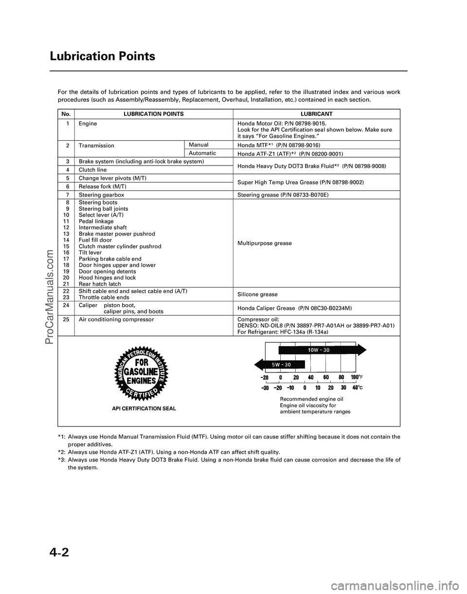
4-2
For the details of lubrication points and types of lubricants to be appl\
ied, refer to the illustrated index and various work
procedures (such as Assembly/Reassembly, Replacement, Overhaul, Install\
ation, etc.) contained in each section.
*1: Always use Honda Manual Transmission Fluid (MTF). Using motor oil can \
cause stiffer shifting because it does not contain theproper additives.
*2: Always use Honda ATF-Z1 (ATF). Using a non-Honda ATF can affect shift \
quality.
*3: Always use Honda Heavy Duty DOT3 Brake Fluid. Using a non-Honda brake fl\
uid can cause corrosion and decrease the life of the system.
Lubrication Points
No.LUBRICATION POINTSLUBRICANT
1Honda Motor Oil: P/N 08798-9015.
Look for the API Certification seal shown below. Make sure
it says “For Gasoline Engines.”
2TransmissionHonda MTF*1(P/N 08798-9016)
3Brake system (including anti-lock brake system)Honda Heavy Duty DOT3 Brake Fluid*3(P/N 08798-9008)4Clutch line
5Change lever pivots (M/T)Super High Temp Urea Grease (P/N 08798-9002)6Release fork (M/T)
8
9
10
11
12
13
14
15
16
17
18
19
20
21Steering boots
Steering ball joints
Select lever (A/T)
Pedal linkage
Intermediate shaft
Brake master power pushrod
Fuel fill door
Clutch master cylinder pushrod
Tilt lever
Parking brake cable end
Door hinges upper and lower
Door opening detents
Hood hinges and lock
Rear hatch latch
Multipurpose grease
24
22
23
Caliper piston boot, caliper pins, and boots
Shift cable end and select cable end (A/T)
Throttle cable ends
Honda Caliper Grease (P/N 08C30-B0234M)
Silicone grease
25Air conditioning compressorCompressor oil:
DENSO: ND-OIL8 (P/N 38897-PR7-A01AH or 38899-PR7-A01)
For Refrigerant: HFC-134a (R-134a)
Manual
Honda ATF-Z1 (ATF)*2(P/N 08200-9001)Automatic
7Steering gearboxSteering grease (P/N 08733-B070E)
Engine
API CERTIFICATION SEAL
Recommended engine oil
Engine oil viscosity for
ambient temperature ranges
*05-NSX (61SW004)SEC04(01-10) 9/22/04 1:49 PM Page 4-2
ProCarManuals.com
Page 530 of 1503
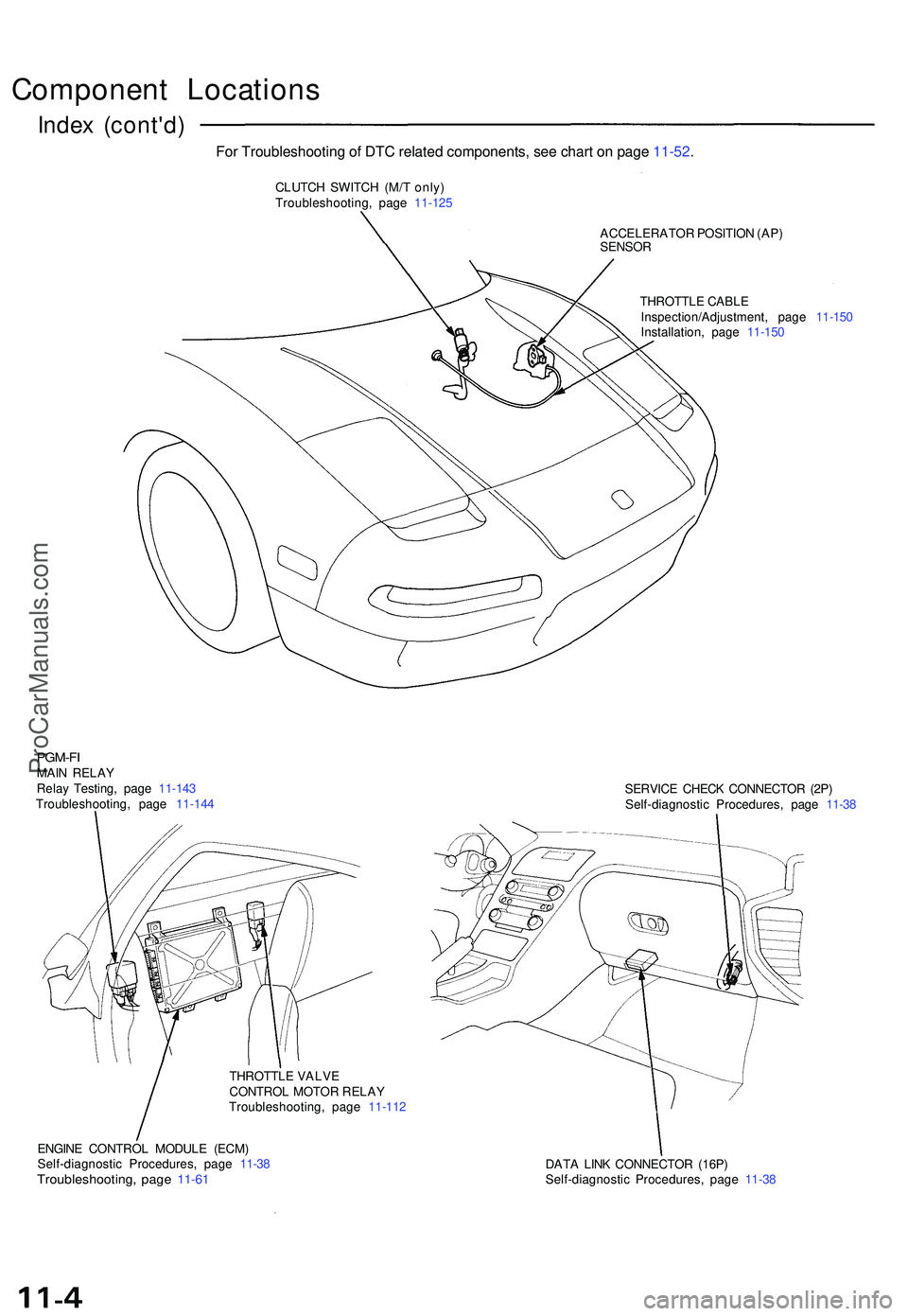
Component Location s
Index (cont'd )
CLUTCH SWITC H (M/ T only )
Troubleshooting , pag e 11-12 5
ACCELERATOR POSITIO N (AP )
SENSO R
THROTTL E CABL E
Inspection/Adjustment , pag e 11-15 0
Installation , pag e 11-15 0
PGM-FIMAIN RELA Y
Rela y Testing , pag e 11-14 3
Troubleshooting , pag e 11-14 4 SERVIC
E CHEC K CONNECTO R (2P )
Self-diagnosti c Procedures , pag e 11-3 8
THROTTL E VALV E
CONTRO L MOTO R RELA Y
Troubleshooting , pag e 11-11 2
ENGIN E CONTRO L MODUL E (ECM )
Self-diagnosti c Procedures , pag e 11-3 8
Troubleshooting , pag e 11-6 1DAT A LIN K CONNECTO R (16P )
Self-diagnosti c Procedures , pag e 11-3 8
For Troubleshooting of DTC related components, see chart on page 11-52.
ProCarManuals.com
Page 572 of 1503
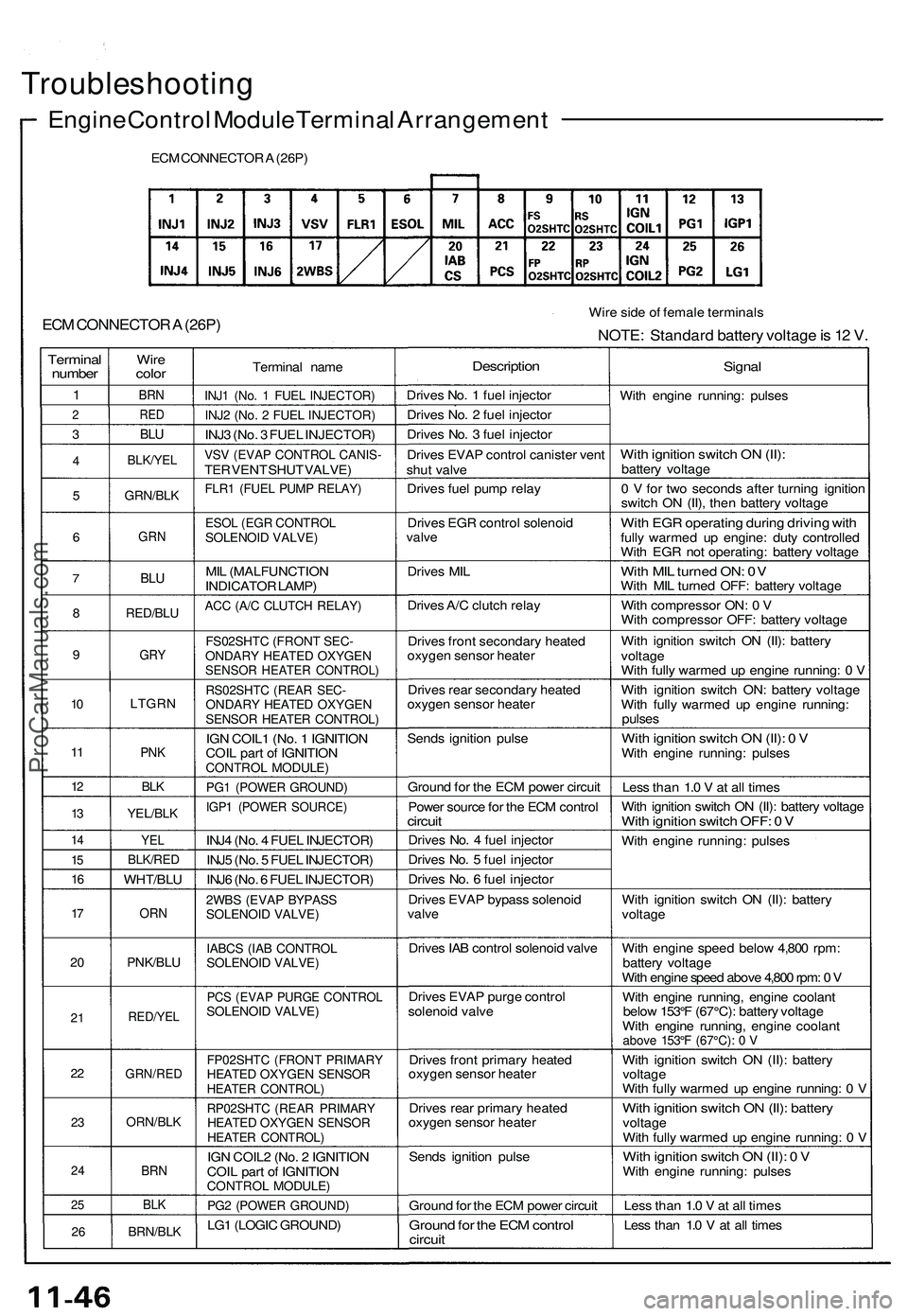
Troubleshooting
Engine Control Module Terminal Arrangement
ECM CONNECTOR A (26P)
ECM CONNECTOR A (26P)
Wire side of female terminals
NOTE: Standard battery voltage is 12 V.
Terminal
number
1
2
3
4
5
6
7
8
9
10
11
12
13
14
15
16
17
20
21
22
23
24
25
26
Wire
color
BRN
RED
BLU
BLK/YEL
GRN/BLK
GRN
BLU
RED/BLU
GRY
LTGRN
PNK
BLK
YEL/BLK
YEL
BLK/RED
WHT/BLU
ORN
PNK/BLU
RED/YEL
GRN/RED
ORN/BLK
BRN
BLK
BRN/BLK
Terminal name
INJ1 (No. 1 FUEL INJECTOR)
INJ2 (No. 2 FUEL INJECTOR)
INJ3 (No. 3 FUEL INJECTOR)
VSV (EVAP CONTROL CANIS-
TER VENT SHUT VALVE)
FLR1 (FUEL PUMP RELAY)
ESOL (EGR CONTROL
SOLENOID VALVE)
MIL (MALFUNCTION
INDICATOR LAMP)
ACC (A/C CLUTCH RELAY)
FS02SHTC (FRONT SEC-
ONDARY HEATED OXYGEN
SENSOR HEATER CONTROL)
RS02SHTC (REAR SEC-
ONDARY HEATED OXYGEN
SENSOR HEATER CONTROL)
IGN COIL1 (No. 1 IGNITION
COIL part of IGNITION
CONTROL MODULE)
PG1 (POWER GROUND)
IGP1 (POWER SOURCE)
INJ4 (No. 4 FUEL INJECTOR)
INJ5 (No. 5 FUEL INJECTOR)
INJ6 (No. 6 FUEL INJECTOR)
2WBS (EVAP BYPASS
SOLENOID VALVE)
IABCS (IAB CONTROL
SOLENOID VALVE)
PCS (EVAP PURGE CONTROL
SOLENOID VALVE)
FP02SHTC (FRONT PRIMARY
HEATED OXYGEN SENSOR
HEATER CONTROL)
RP02SHTC (REAR PRIMARY
HEATED OXYGEN SENSOR
HEATER CONTROL)
IGN COIL2 (No. 2 IGNITION
COIL part of IGNITION
CONTROL MODULE)
PG2 (POWER GROUND)
LG1 (LOGIC GROUND)
Description
Drives No. 1 fuel injector
Drives No. 2 fuel injector
Drives No. 3 fuel injector
Drives EVAP control canister vent
shut valve
Drives fuel pump relay
Drives EGR control solenoid
valve
Drives MIL
Drives A/C clutch relay
Drives front secondary heated
oxygen sensor heater
Drives rear secondary heated
oxygen sensor heater
Sends ignition pulse
Ground for the ECM power circuit
Power source for the ECM control
circuit
Drives No. 4 fuel injector
Drives No. 5 fuel injector
Drives No. 6 fuel injector
Drives EVAP bypass solenoid
valve
Drives IAB control solenoid valve
Drives EVAP purge control
solenoid valve
Drives front primary heated
oxygen sensor heater
Drives rear primary heated
oxygen sensor heater
Sends ignition pulse
Ground for the ECM power circuit
Ground for the ECM control
circuit
Signal
With engine running: pulses
With ignition switch ON (II):
battery voltage
0 V for two seconds after turning ignition
switch ON (II), then battery voltage
With EGR operating during driving with
fully warmed up engine: duty controlled
With EGR not operating: battery voltage
With MIL turned ON: 0V
With MIL turned OFF: battery voltage
With compressor ON: 0 V
With compressor OFF: battery voltage
With ignition switch ON (II): battery
voltage
With fully warmed up engine running: 0 V
With ignition switch ON: battery voltage
With fully warmed up engine running:
pulses
With ignition switch ON (II): 0 V
With engine running: pulses
Less than 1.0 V at all times
With ignition switch ON (II): battery voltage
With ignition switch OFF: 0 V
With engine running: pulses
With ignition switch ON (II): battery
voltage
With engine speed below 4,800 rpm:
battery voltage
With engine speed above 4,800 rpm: 0 V
With engine running, engine coolant
below 153°F (67°C): battery voltage
With engine running, engine coolant
above 153°F (67°C): 0 V
With ignition switch ON (II): battery
voltage
With fully warmed up engine running: 0 V
With ignition switch ON (II): battery
voltage
With fully warmed up engine running: 0 V
With ignition switch ON (II): 0 V
With engine running: pulses
Less than 1.0 V at all times
Less than 1.0 V at all timesProCarManuals.com
Page 576 of 1503
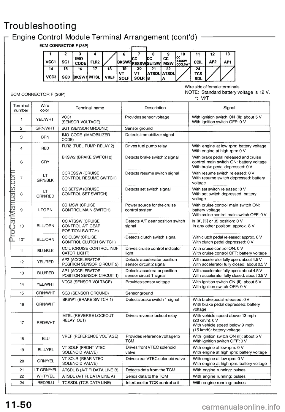
Troubleshooting
Engine Control Module Terminal Arrangement (cont'd)
ECM CONNECTOR F (26P)
Wire side of female terminals
NOTE: Standard battery voltage is 12 V.
*: M/T
Terminal
number
1
2
3
4
6
7
8
9
10
10*
11
12
13
14
15
16
17
18
19
20
21
22
24
Wire
color
YEL/WHT
GRN/WHT
BRN
RED
GRY
LT
GRN/BLK
LT
GRN/RED
LTGRN
BLU/ORN
BLU/ORN
BLU/BLK
YEL/RED
BLU/RED
YEL/WHT
GRN/WHT
GRN/WHT
RED/WHT
BLU
BLU/YEL
GRN/YEL
LT GRN/YEL
WHT/YEL
RED/BLU
Terminal name
VCC1
(SENSOR VOLTAGE)
SG1 (SENSOR GROUND)
IMO CODE (IMMOBILIZER
CODE)
FLR2 (FUEL PUMP RELAY 2)
BKSW2 (BRAKE SWITCH 2)
CCRESSW (CRUISE
CONTROL RESUME SWITCH)
CC SETSW (CRUISE
CONTROL SET SWITCH)
CC MSW (CRUISE
CONTROL MAIN SWITCH)
CC ATSSW (CRUISE
CONTROL A/T GEAR
POSITION SWITCH)
CC CLSW (CRUISE
CONTROL CLUTCH SWITCH)
CCIL (CRUISE CONTROL INDI-
CATOR LIGHT)
AP2 (ACCELERATOR
POSITION SENSOR CIRCUIT 2)
AP1 (ACCELERATOR
POSITION SENSOR CIRCUIT 1)
VCC3 (SENSOR VOLTAGE)
SG3 (SENSOR GROUND)
BKSW1 (BRAKE SWITCH 1)
MTSL (REVERSE LOCKOUT
RELAY OUT)
VREF (REFERENCE VOLTAGE)
VT SOLF (FRONT VTEC
SOLENOID VALVE)
VT SOLR (REAR VTEC
SOLENOID VALVE)
ATSDL B (A/T Fl DATA LINE B)
ATSDL (A/T Fl. DATA LINE A)
TCSSDL (TCS DATA LINE)
Description
Provides sensor voltage
Sensor ground
Detects immobilizer signal
Drives fuel pump relay
Detects brake switch 2 signal
Detects resume switch signal
Detects set switch signal
Power source for the cruise
control system
Detects A/T gear position switch
signal
Detects clutch switch signal
Drives cruise control indicator
light
Detects accelerator position
sensor circuit 2 signal
Detects accelerator position
sensor circuit 1 signal
Provides sensor voltage
Sensor ground
Detects brake switch 1 signal
Drives reverse lockout relay
Provides reference voltage to
TCM
Drives front VTEC solenoid
valve
Drives rear VTEC solenoid valve
Detects data from the TCM
Sends data to the TCM
Interface for TCS control unit
Signal
With ignition switch ON (II): about 5 V
With ignition switch OFF: 0 V
With engine at low rpm: battery voltage
With engine at high rpm: 0 V
With brake pedal released and cruise
control main switch ON: battery voltage
With brake pedal depressed: 0 V
With resume switch released: 0 V
With resume switch depressed: battery
voltage
With set switch released: 0 V
With set switch depressed: battery
voltage
With cruise control main switch ON:
battery voltage
With cruise control main switch OFF: 0 V
In , or position: 0 V
In any other position: approx. 8 V
With clutch pedal released: approx. 8 V
With clutch pedal depressed: 0 V
With cruise control ON: 0 V
With cruise control OFF: battery voltage
With accelerator fully open: about 4.5 V
With accelerator fully closed: about 0.5 V
With accelerator fully open: about 4.5 V
With accelerator fully closed: about 0.5 V
With ignition switch ON (II): about 5 V
With ignition switch OFF: 0 V
With brake pedal released: 0 V
With brake pedal depressed: battery
voltage
With vehicle speed above 13 mph
(20 km/h): 0 V
With vehicle speed below 9 mph
(15 km/h): battery voltage
With ignition switch ON (II): about 5 V
With ignition switch OFF: 0 V
With engine at low rpm: 0 V
With engine at high rpm: battery voltage
With engine at low rpm: 0 V
With engine at high rpm: battery voltage
With engine running: pulses
With engine running: pulses
With engine running: pulsesProCarManuals.com