alarm ACURA NSX 1997 Service Repair Manual
[x] Cancel search | Manufacturer: ACURA, Model Year: 1997, Model line: NSX, Model: ACURA NSX 1997Pages: 1503, PDF Size: 57.08 MB
Page 280 of 1503
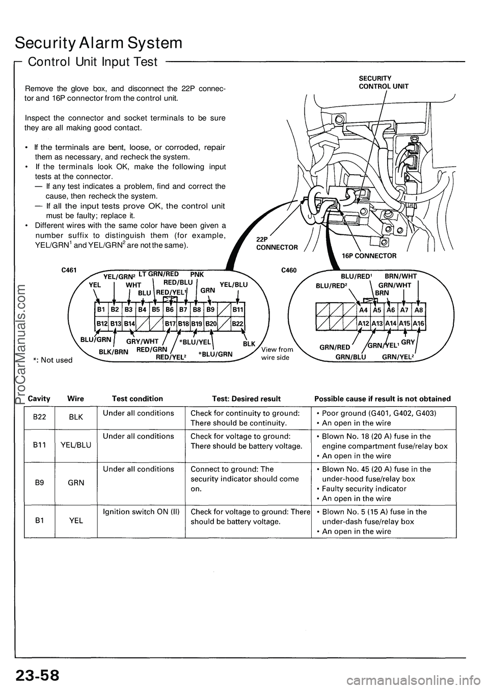
Security Alarm System
Control Unit Input Test
Remove the glove box, and disconnect the 22P connec-
tor and 16P connector from the control unit.
Inspect the connector and socket terminals to be sure
they are all making good contact.
• If the terminals are bent, loose, or corroded, repair
them as necessary, and recheck the system.
• If the terminals look OK, make the following input
tests at the connector.
If any test indicates a problem, find and correct the
cause, then recheck the system.
If all the input tests prove OK, the control unit
must be faulty; replace it.
• Different wires with the same color have been given a
number suffix to distinguish them (for example,
YEL/GRN1 and YEL/GRN2 are not the same).ProCarManuals.com
Page 360 of 1503
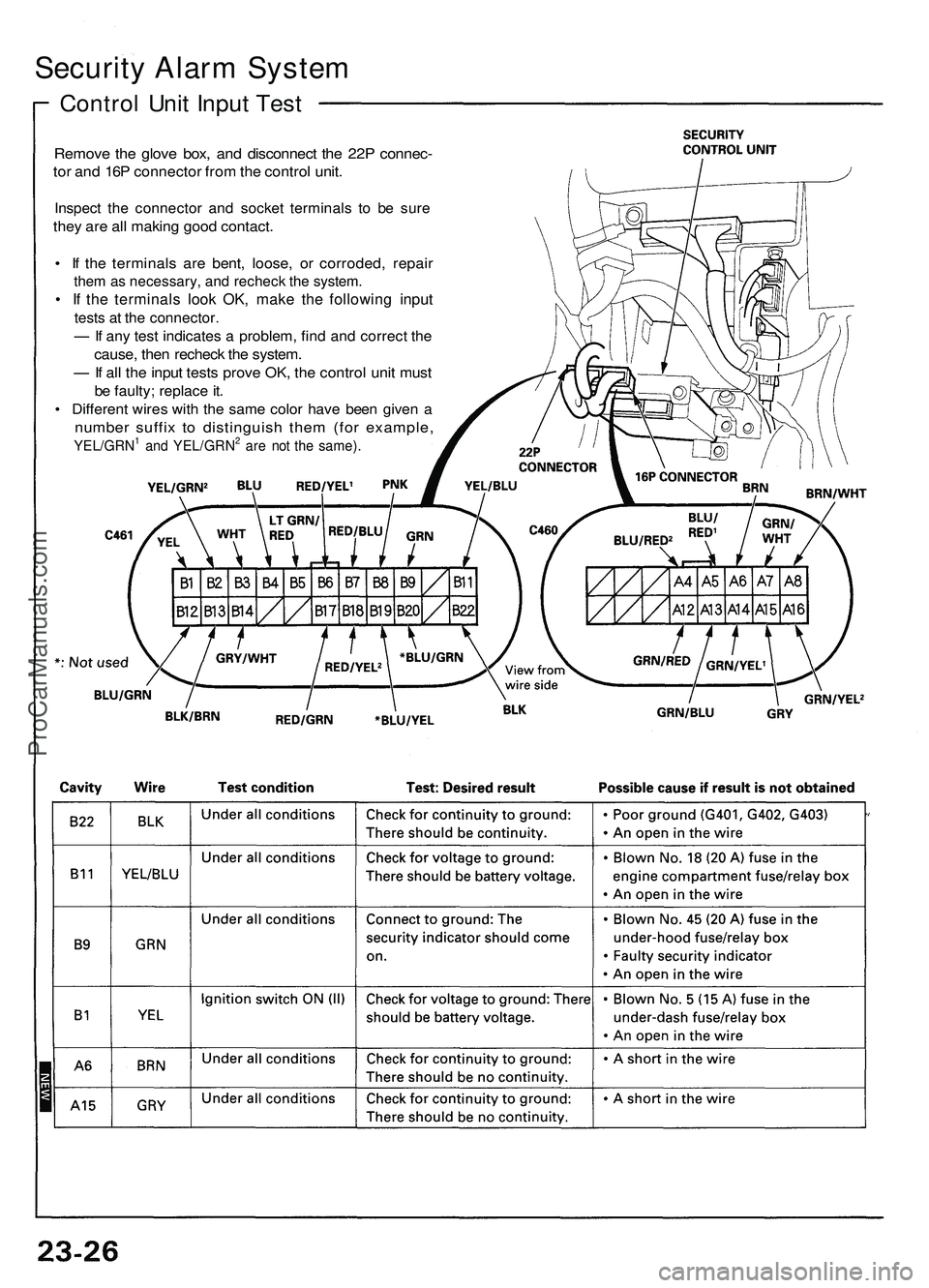
Security Alarm System
Control Unit Input Test
Remove the glove box, and disconnect the 22P connec-
tor and 16P connector from the control unit.
Inspect the connector and socket terminals to be sure
they are all making good contact.
• If the terminals are bent, loose, or corroded, repair
them as necessary, and recheck the system.
• If the terminals look OK, make the following input
tests at the connector.
— If any test indicates a problem, find and correct the
cause, then recheck the system.
— If all the input tests prove OK, the control unit must
be faulty; replace it.
• Different wires with the same color have been given a
number suffix to distinguish them (for example,
YEL/GRN1 and YEL/GRN2 are not the same).ProCarManuals.com
Page 362 of 1503
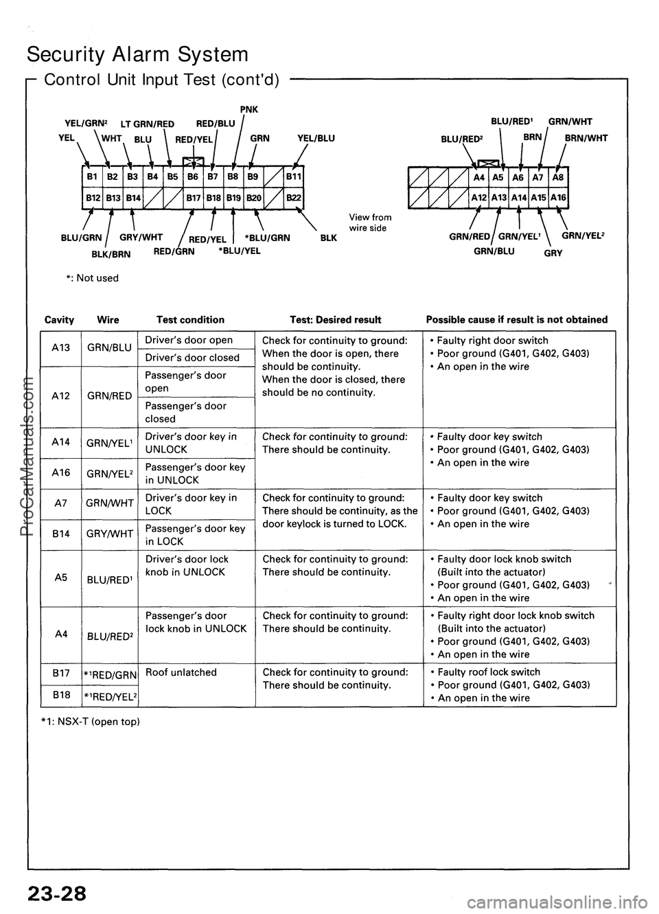
Security Alarm System
Control Unit Input Test (cont'd)ProCarManuals.com
Page 1064 of 1503
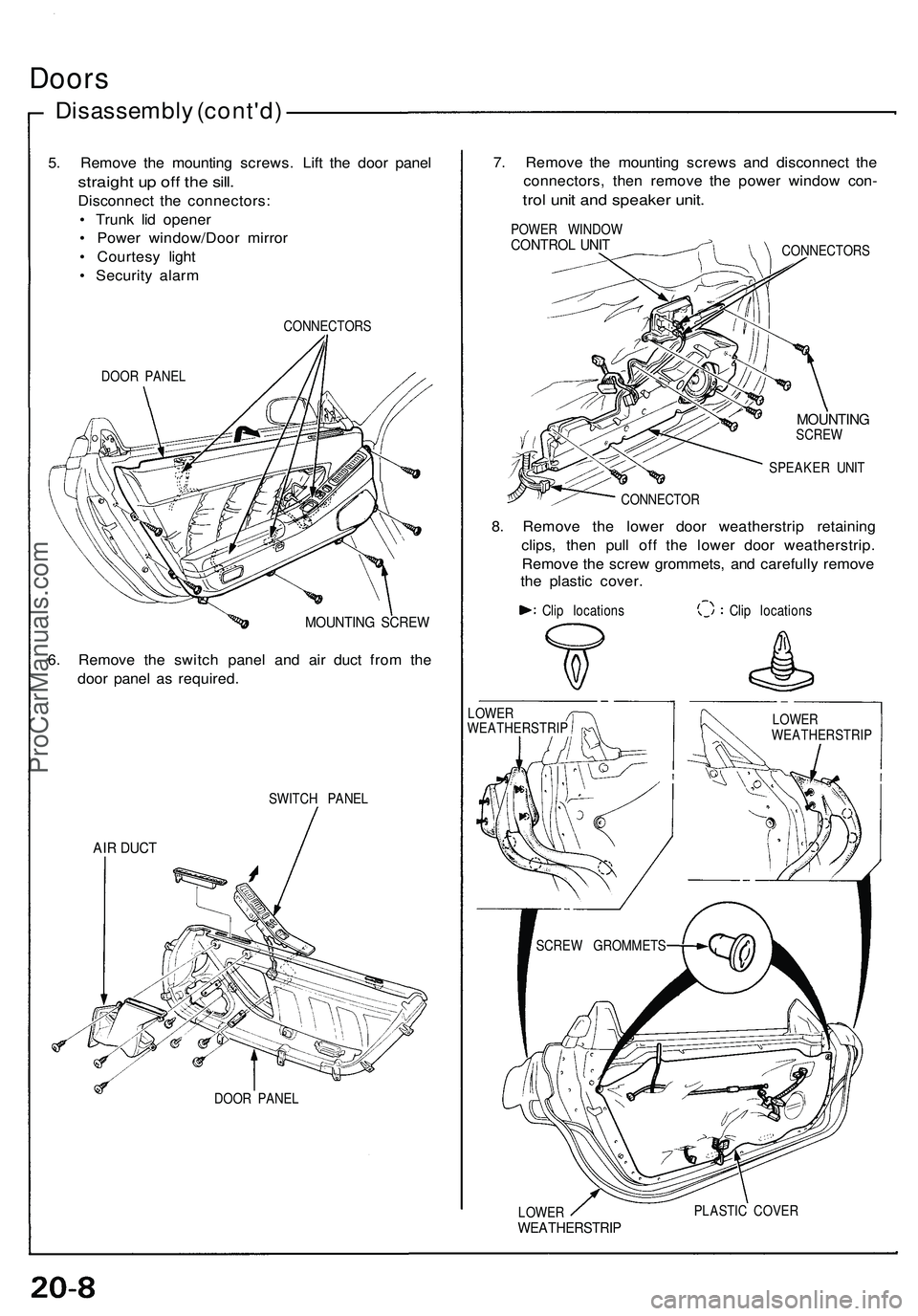
Doors
Disassembly (cont'd)
5. Remove the mounting screws. Lift the door panel
straight up off the sill.
Disconnect the connectors:
• Trunk lid opener
• Power window/Door mirror
• Courtesy light
• Security alarm
DOOR PANEL
CONNECTORS
MOUNTING SCREW
6. Remove the switch panel and air duct from the
door panel as required.
SWITCH PANEL
AIR DUCT
DOOR PANEL
7. Remove the mounting screws and disconnect the
connectors, then remove the power window con-
trol unit and speaker unit.
POWER WINDOW
CONTROL UNIT
CONNECTORS
MOUNTING
SCREW
SPEAKER UNIT
CONNECTOR
8. Remove the lower door weatherstrip retaining
clips, then pull off the lower door weatherstrip.
Remove the screw grommets, and carefully remove
the plastic cover.
Clip locations
Clip locations
LOWER
WEATHERSTRIP
PLASTIC COVER
LOWER
WEATHERSTRIP
LOWER
WEATHERSTRIP
SCREW GROMMETSProCarManuals.com
Page 1251 of 1503
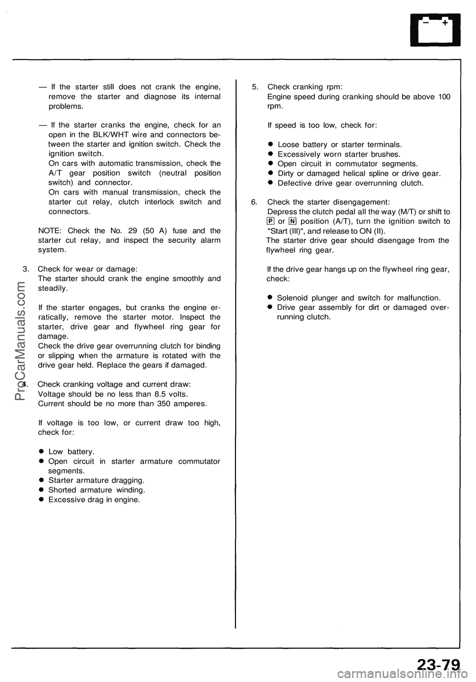
— If the starter still does not crank the engine,
remove the starter and diagnose its internal
problems.
— If the starter cranks the engine, check for an
open in the BLK/WHT wire and connectors be-
tween the starter and ignition switch. Check the
ignition switch.
On cars with automatic transmission, check the
A/T gear position switch (neutral position
switch) and connector.
On cars with manual transmission, check the
starter cut relay, clutch interlock switch and
connectors.
NOTE: Check the No. 29 (50 A) fuse and the
starter cut relay, and inspect the security alarm
system.
3. Check for wear or damage:
The starter should crank the engine smoothly and
steadily.
If the starter engages, but cranks the engine er-
ratically, remove the starter motor. Inspect the
starter, drive gear and flywheel ring gear for
damage.
Check the drive gear overrunning clutch for binding
or slipping when the armature is rotated with the
drive gear held. Replace the gears if damaged.
4. Check cranking voltage and current draw:
Voltage should be no less than 8.5 volts.
Current should be no more than 350 amperes.
If voltage is too low, or current draw too high,
check for:
Low battery.
Open circuit in starter armature commutator
segments.
Starter armature dragging.
Shorted armature winding.
Excessive drag in engine.
5. Check cranking rpm:
Engine speed during cranking should be above 100
rpm.
If speed is too low, check for:
Loose battery or starter terminals.
Excessively worn starter brushes.
Open circuit in commutator segments.
Dirty or damaged helical spline or drive gear.
Defective drive gear overrunning clutch.
6. Check the starter disengagement:
Depress the clutch pedal all the way (M/T) or shift to
or position (A/T), turn the ignition switch to
"Start (III)", and release to ON (II).
The starter drive gear should disengage from the
flywheel ring gear.
If the drive gear hangs up on the flywheel ring gear,
check:
Solenoid plunger and switch for malfunction.
Drive gear assembly for dirt or damaged over-
running clutch.ProCarManuals.com
Page 1460 of 1503
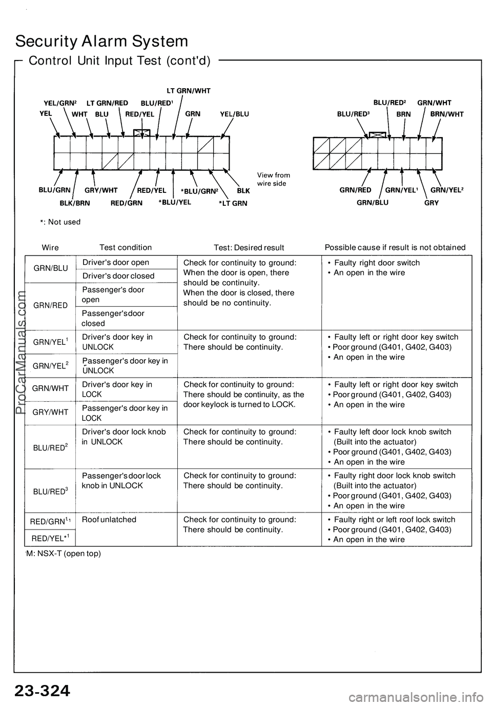
Security Alarm System
Control Unit Input Test (cont'd)
Test condition
Test: Desired result
Possible cause if result is not obtained
GRN/BLU
GRN/RED
Driver's door open
Driver's door closed
Passenger's door
open
Passenger's door
closed
Check for continuity to ground:
When the door is open, there
should be continuity.
When the door is closed, there
should be no continuity.
• Faulty right door switch
• An open in the wire
GRN/YEL1
Driver's door key in
UNLOCK
Check for continuity to ground:
There should be continuity.
GRN/YEL2
Passenger's door key in
UNLOCK
• Faulty left or right door key switch
• Poor ground (G401, G402, G403)
• An open in the wire
GRN/WHT
Driver's door key in
LOCK
GRY/WHT
Passenger's door key in
LOCK
Check for continuity to ground:
There should be continuity, as the
door keylock is turned to LOCK.
• Faulty left or right door key switch
• Poor ground (G401, G402, G403)
• An open in the wire
BLU/RED2
Driver's door lock knob
in UNLOCK
Check for continuity to ground:
There should be continuity.
• Faulty left door lock knob switch
(Built into the actuator)
• Poor ground (G401, G402, G403)
• An open in the wire
BLU/RED3
Passenger's door lock
knob in UNLOCK
Check for continuity to ground:
There should be continuity.
• Faulty right door lock knob switch
(Built into the actuator)
• Poor ground (G401, G402, G403)
• An open in the wire
RED/GRN1
Roof unlatched
RED/YEL*1
Check for continuity to ground:
There should be continuity.
• Faulty right or left roof lock switch
• Poor ground (G401, G402, G403)
• An open in the wire
M: NSX-T (open top)
WireProCarManuals.com