drain bolt ACURA NSX 1997 Service Repair Manual
[x] Cancel search | Manufacturer: ACURA, Model Year: 1997, Model line: NSX, Model: ACURA NSX 1997Pages: 1503, PDF Size: 57.08 MB
Page 193 of 1503
Radiator
Engine Coolant Refilling and Bleeding
CAUTION: When pouring engine coolant, be sure to
shut the relay box lid and not let coolant spill on the
electrical parts or the paint. If any coolant spills, rinse it
off immediately.
NOTE:
• Perform this maintenance when the engine is cool.
• Before replacing the coolant, turn the ignition ON,
slowly turn the climate control temperature knob to
90° and turn off the ignition. This will allow the
coolant in the heater to drain out with the rest of the
system.
1. Open the hood, the rear window and the engine
cover.
2. Remove the cover protecting the water pipes and
shift cables on the underside of the car.
3. Before removing the expansion tank cap, first
loosen the cap to lower pressure.
CAUTION: Do not remove the expansion tank cap
when engine is hot. The coolant is under pressure
and may blow out and scald you. Open the cap
slowly when the engine is cool.
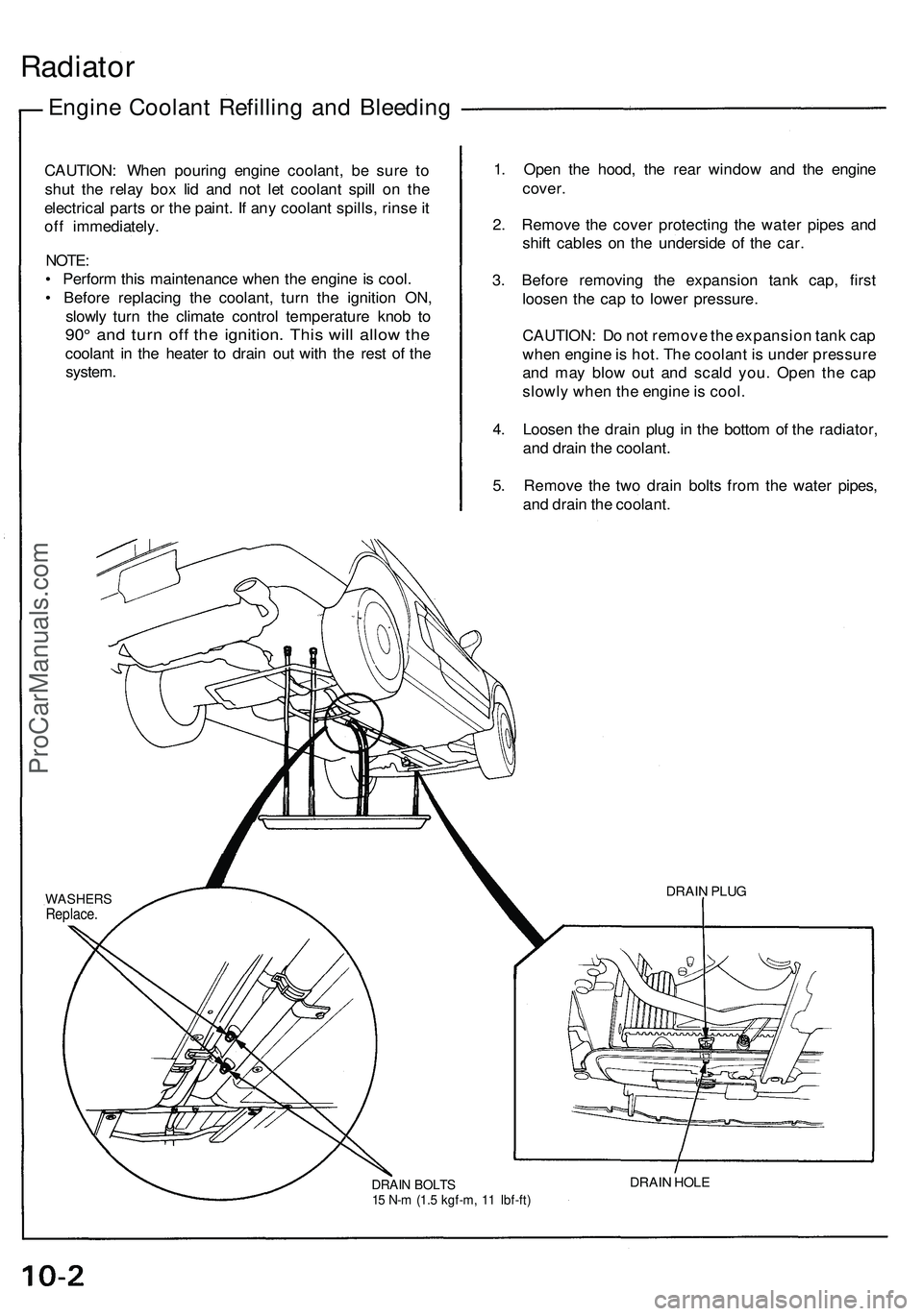
4. Loosen the drain plug in the bottom of the radiator,
and drain the coolant.
5. Remove the two drain bolts from the water pipes,
and drain the coolant.
DRAIN BOLTS
15 N-m (1.5 kgf-m, 11 Ibf-ft)
DRAIN HOLE
DRAIN PLUG
WASHERS
Replace.ProCarManuals.com
Page 194 of 1503
Engine Coolan t Refillin g an d Bleedin g (cont'd )
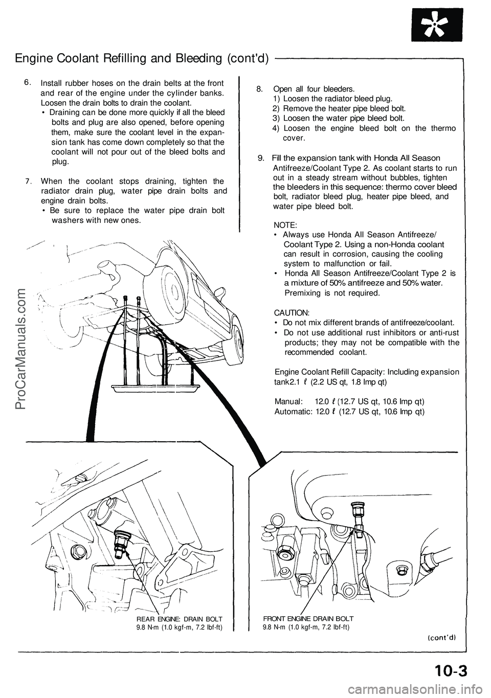
Install rubbe r hose s o n th e drai n belt s a t th e fron t
an d rea r o f th e engin e unde r th e cylinde r banks .
Loose n th e drai n bolt s t o drai n th e coolant .
• Drainin g ca n b e don e mor e quickl y if al l th e blee d
bolt s an d plu g ar e als o opened , befor e openin g
them , mak e sur e th e coolan t leve l i n th e expan -
sio n tan k ha s com e dow n completel y s o tha t th e
coolan t wil l no t pou r ou t o f th e blee d bolt s an d
plug .
Whe n th e coolan t stop s draining , tighte n th e
radiato r drai n plug , wate r pip e drain bolt s an d
engin e drai n bolts .
• B e sur e t o replac e th e wate r pip e drai n bol t
washer s wit h ne w ones . 8
. Ope n al l fou r bleeders .
1 ) Loose n th e radiato r blee d plug .
2 ) Remov e th e heate r pip e blee d bolt .
3) Loose n th e wate r pip e blee d bolt .
4) Loose n th e engin e blee d bol t o n th e therm o
cover.
9. Fil l th e expansio n tan k wit h Hond a Al l Seaso n
Antifreeze/Coolan t Typ e 2 . A s coolan t start s t o ru n
ou t i n a stead y strea m withou t bubbles , tighte n
the bleeder s in thi s sequence : therm o cove r blee d
bolt, radiato r blee d plug , heate r pip e bleed , an d
wate r pip e blee d bolt .
NOTE :
• Alway s us e Hond a Al l Seaso n Antifreeze /
Coolant Typ e 2 . Usin g a non-Hond a coolan t
can resul t i n corrosion , causin g th e coolin g
syste m to malfunctio n o r fail .
• Hond a Al l Seaso n Antifreeze/Coolan t Typ e 2 is
a mixtur e o f 50 % antifreez e an d 50 % water .
Premixin g i s no t required .
CAUTION :
• D o no t mi x differen t brand s o f antifreeze/coolant .
• D o no t us e additiona l rus t inhibitor s o r anti-rus t
products ; the y ma y no t b e compatibl e wit h th e
recommende d coolant .
Engin e Coolan t Refil l Capacity : Includin g expansio n
tank 2. 1 (2. 2 U S qt , 1. 8 Im p qt )
Manual : 12. 0 (12. 7 U S qt , 10. 6 Im p qt )
Automatic : 12. 0 (12. 7 U S qt , 10. 6 Im p qt )
REA R ENGINE : DRAI N BOL T9.8 N- m (1. 0 kgf-m , 7. 2 Ibf-ft )FRON T ENGIN E DRAI N BOL T9.8 N- m (1. 0 kgf-m , 7. 2 Ibf-ft )
ProCarManuals.com
Page 521 of 1503
Engine Coolant Refilling and Bleeding
CAUTION: When pouring engine coolant, be sure to
shut the relay box lid and not let coolant spill on the
electrical parts or the paint. If any coolant spills, rinse it
off immediately.
NOTE:
• Perform this maintenance when the engine is cool.
• Before replacing the coolant, turn the ignition ON,
slowly turn the climate control temperature knob to
90° and turn off the ignition. This will allow the
coolant in the heater to drain out with the rest of the
system.
1. Open the hood, the rear window and the engine
cover.
2. Remove the cover protecting the water pipes and
shift cables on the underside of the car.
3. Before removing the expansion tank cap, first
loosen the cap to lower pressure.
CAUTION: Do not remove the expansion tank cap
when engine is hot. The coolant is under pressure
and may blow out and scald you. Open the cap
slowly when the engine is cool.
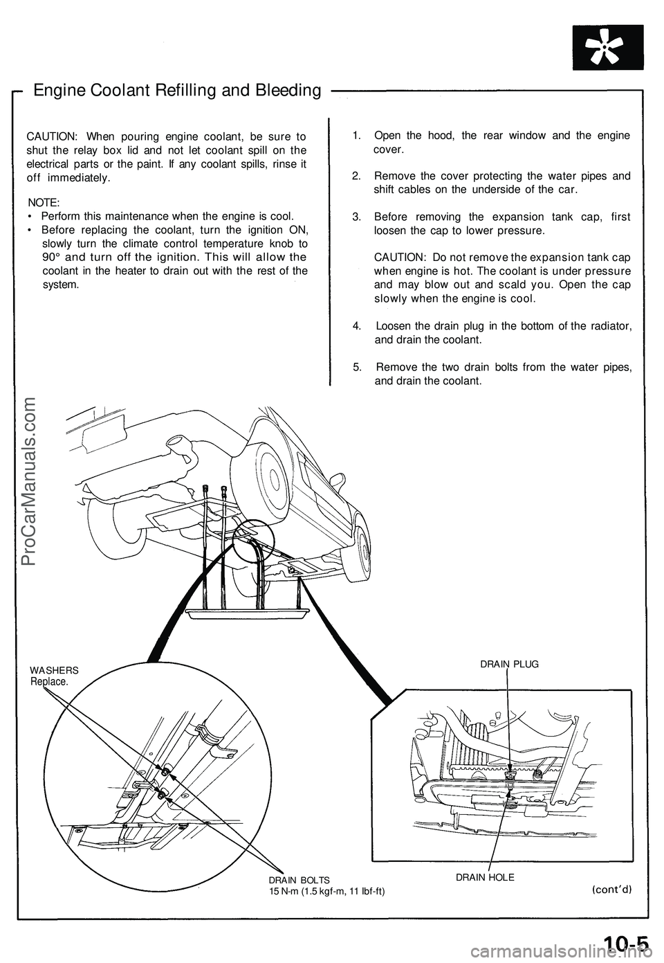
4. Loosen the drain plug in the bottom of the radiator,
and drain the coolant.
5. Remove the two drain bolts from the water pipes,
and drain the coolant.
WASHERS
Replace.
DRAIN BOLTS
15 N-m (1.5 kgf-m, 11 Ibf-ft)
DRAIN HOLE
DRAIN PLUGProCarManuals.com
Page 522 of 1503
Radiator
Engine Coolan t Refillin g an d Bleedin g (cont'd)
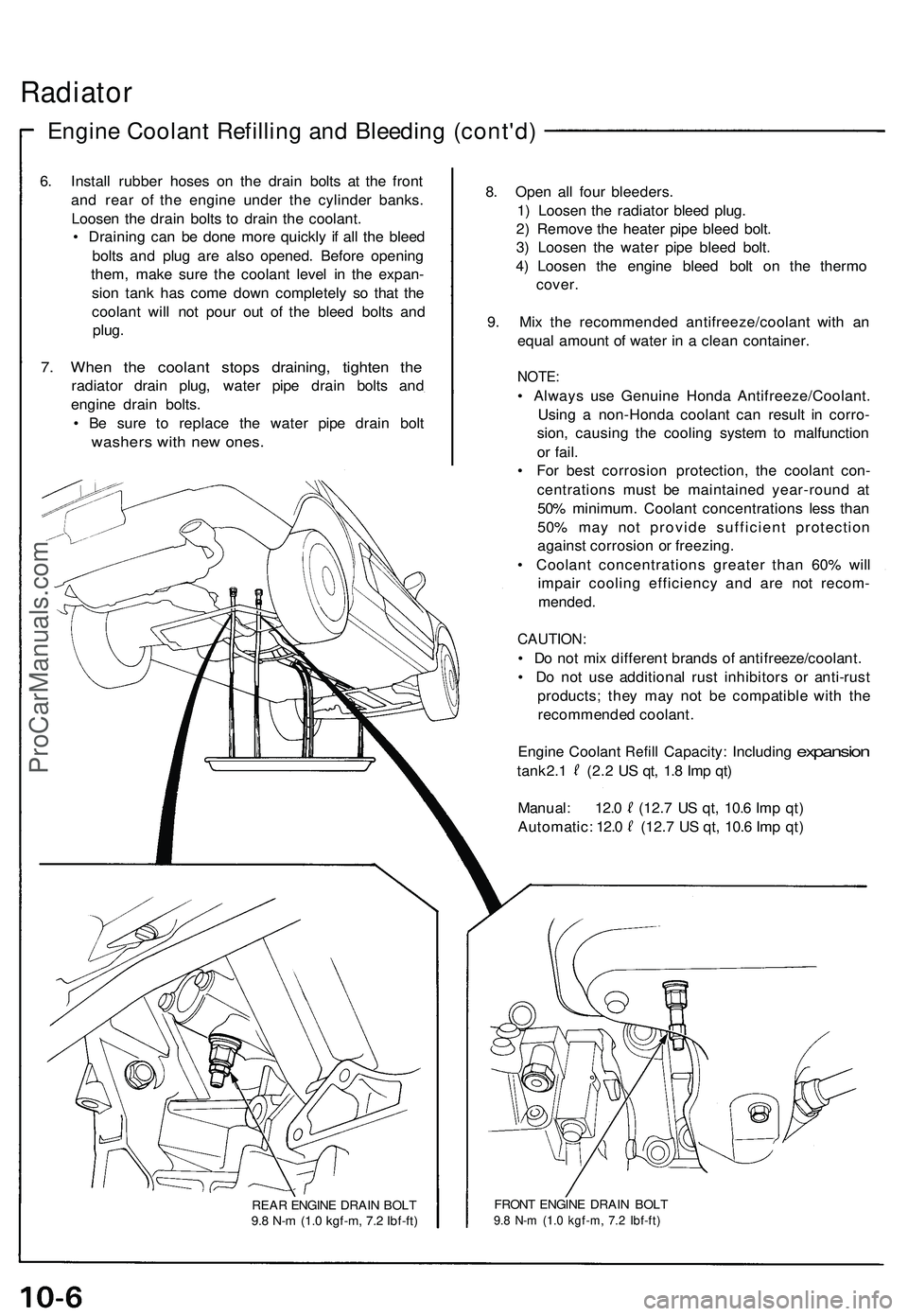
6. Instal l rubbe r hose s o n th e drai n bolt s a t th e fron t
an d rea r o f th e engin e unde r th e cylinde r banks .
Loose n th e drai n bolt s t o drai n th e coolant .
• Drainin g ca n b e don e mor e quickl y i f al l th e blee d
bolt s an d plu g ar e als o opened . Befor e openin g
them , mak e sur e th e coolan t leve l i n th e expan -
sio n tan k ha s com e dow n completel y s o tha t th e
coolan t wil l no t pou r ou t o f th e blee d bolt s an d
plug .
7. Whe n th e coolan t stop s draining , tighte n th e
radiato r drai n plug , wate r pip e drai n bolt s an d
engin e drai n bolts .
• B e sur e t o replac e th e wate r pip e drai n bol t
washer s wit h ne w ones .
REAR ENGIN E DRAI N BOL T
9. 8 N- m (1. 0 kgf-m , 7. 2 Ibf-ft )
8. Ope n al l fou r bleeders .
1 ) Loose n th e radiato r blee d plug .
2 ) Remov e th e heate r pip e blee d bolt .
3 ) Loose n th e wate r pip e blee d bolt .
4 ) Loose n th e engin e blee d bol t o n th e therm o
cover .
9 . Mi x th e recommende d antifreeze/coolan t wit h a n
equa l amoun t o f wate r i n a clea n container .
NOTE:
• Alway s us e Genuin e Hond a Antifreeze/Coolant .
Usin g a non-Hond a coolan t ca n resul t i n corro -
sion , causin g th e coolin g syste m to malfunctio n
o r fail .
• Fo r bes t corrosio n protection , th e coolan t con -
centration s mus t b e maintaine d year-roun d a t
50 % minimum . Coolan t concentration s les s tha n
50 % ma y no t provid e sufficien t protectio n
agains t corrosio n o r freezing .
• Coolan t concentration s greate r tha n 60 % wil l
impai r coolin g efficienc y an d ar e no t recom -
mended .
CAUTION :
• D o no t mi x differen t brand s o f antifreeze/coolant .
• D o no t us e additiona l rus t inhibitor s o r anti-rus t
products ; the y ma y no t b e compatibl e wit h th e
recommende d coolant .
Engin e Coolan t
Refill Capacity : Includin g expansion
tank 2. 1 (2. 2 U S qt , 1. 8 Im p qt )
Manual : 12. 0 (12. 7 U S qt , 10. 6 Im p qt )
Automatic : 12. 0 (12. 7 U S qt , 10. 6 Im p qt )
FRON T ENGIN E DRAI N BOL T9.8 N- m (1. 0 kgf-m , 7. 2 Ibf-ft )
ProCarManuals.com
Page 526 of 1503
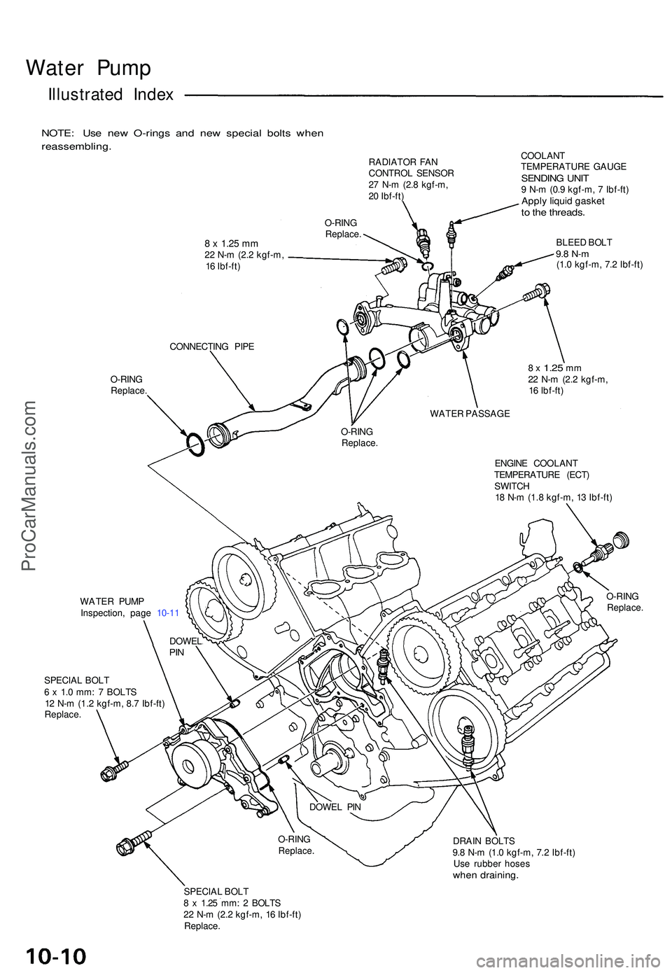
Water Pum p
Illustrate d Inde x
NOTE : Us e ne w O-ring s an d ne w specia l bolt s whe n
reassembling .
RADIATOR FA N
CONTRO L SENSO R
2 7 N- m (2. 8 kgf-m ,
2 0 Ibf-ft )
8 x 1.2 5 mm22 N- m (2. 2 kgf-m ,
1 6 Ibf-ft ) O-RIN
G
Replace .
O-RING
Replace . COOLAN
T
TEMPERATUR E GAUG E
SENDIN G UNI T9 N- m (0. 9 kgf-m , 7 Ibf-ft )Apply liqui d gaske tto th e threads .
BLEED BOL T9.8 N- m(1.0 kgf-m , 7. 2 Ibf-ft )
CONNECTIN G PIP E
8 x 1.2 5 mm22 N- m (2. 2 kgf-m ,
1 6 Ibf-ft )
WATE R PASSAG E
O-RIN G
Replace .
ENGINE COOLAN T
TEMPERATUR E (ECT )
SWITC H
1 8 N- m (1. 8 kgf-m , 1 3 Ibf-ft )
WATE R PUM P
Inspection , pag e 10-1 1 O-RIN
G
Replace .
SPECIAL BOL T
6 x 1. 0 mm : 7 BOLT S
1 2 N- m (1.2 kgf-m , 8. 7 Ibf-ft )
Replace .
DRAIN BOLT S
9. 8 N- m (1. 0 kgf-m , 7. 2 Ibf-ft )
Us e rubbe r hose s
when draining .
SPECIAL BOL T
8 x 1.2 5 mm : 2 BOLT S
2 2 N- m (2. 2 kgf-m , 1 6 Ibf-ft )
Replace .
DOWELPIN
DOWE L PI N
O-RIN G
Replace .
ProCarManuals.com
Page 621 of 1503
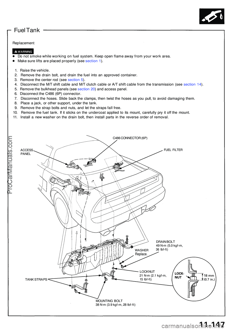
Fuel Tan k
Replacemen t
D o no t smok e whil e workin g o n fue l system . Kee p ope n flam e awa y fro m you r wor k area .
Mak e sur e lift s ar e place d properl y (se e sectio n 1 ).
1 . Rais e th e vehicle .
2 . Remov e th e drai n bolt , an d drai n th e fue l int o a n approve d container .
3 . Remov e th e cente r ro d (se e sectio n 5 ).
4 . Disconnec t th e M/ T shif t cabl e an d M/ T clutc h cabl e o r A/ T shif t cabl e fro m th e transmissio n (se e sectio n 14 ).
5 . Remov e th e bulkhea d panel s (se e sectio n 20 ) an d acces s panel .
6 . Disconnec t th e C48 6 (6P ) connector .
7 . Disconnec t th e hoses . Slid e bac k th e clamps , the n twis t th e hose s a s yo u pull , t o avoi d damagin g them .
8 . Plac e a jack , o r othe r support , unde r th e tank .
9 . Remov e th e stra p bolt s an d nuts , an d le t th e strap s fal l free .
10 . Remov e th e fue l tank . I f i t stick s o n th e undercoa t applie d t o it s mount , carefull y pr y i t of f th e mount .
11 . Instal l a ne w washe r o n th e drai n bolt , the n instal l part s i n th e revers e orde r o f removal .
C486 CONNECTO R (6P )
ACCES SPANELFUEL FILTE R
DRAIN BOL T
4 9 N- m (5. 0 kgf-m ,
36 Ibf-ft )
TANK STRAP S LOCKNU
T
2 1 N- m (2. 1 kgf-m ,15 Ibf-ft )
MOUNTIN G BOL T
3 8 N- m (3. 9 kgf-m , 2 8 Ibf-ft )
WASHE RReplace.
ProCarManuals.com
Page 665 of 1503
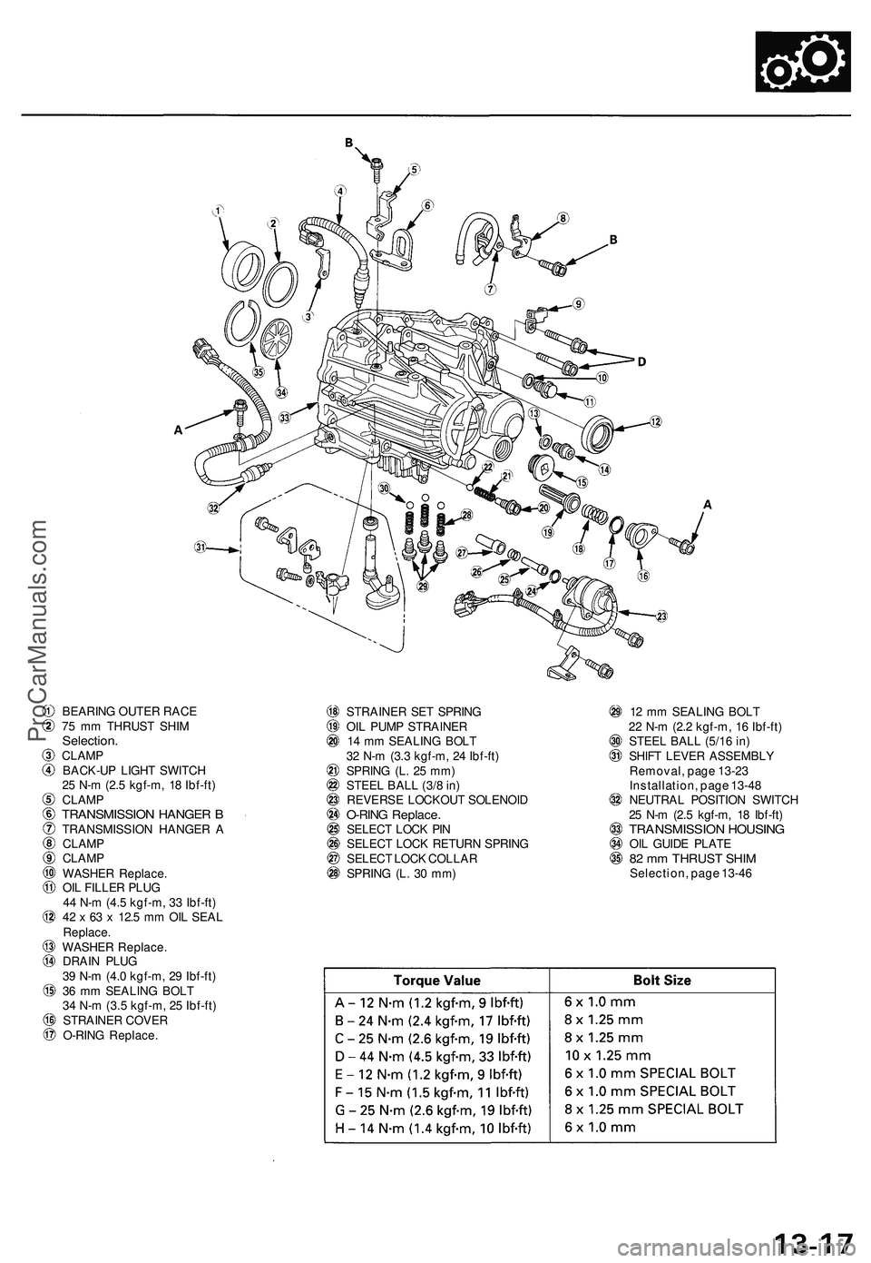
BEARING OUTER RACE
75 mm THRUST SHIM
Selection.
CLAMP
BACK-UP LIGHT SWITCH
25 N-m (2.5 kgf-m, 18 Ibf-ft)
CLAMP
TRANSMISSION HANGER B
TRANSMISSION HANGER A
CLAMP
CLAMP
WASHER Replace.
OIL FILLER PLUG
44 N-m (4.5 kgf-m, 33 Ibf-ft)
42 x 63 x 12.5 mm OIL SEAL
Replace.
WASHER Replace.
DRAIN PLUG
39 N-m (4.0 kgf-m, 29 Ibf-ft)
36 mm SEALING BOLT
34 N-m (3.5 kgf-m, 25 Ibf-ft)
STRAINER COVER
O-RING Replace.
STRAINER SET SPRING
OIL PUMP STRAINER
14 mm SEALING BOLT
32 N-m (3.3 kgf-m, 24 Ibf-ft)
SPRING (L. 25 mm)
STEEL BALL (3/8 in)
REVERSE LOCKOUT SOLENOID
O-RING Replace.
SELECT LOCK PIN
SELECT LOCK RETURN SPRING
SELECT LOCK COLLAR
SPRING (L. 30 mm)
12 mm SEALING BOLT
22 N-m (2.2 kgf-m, 16 Ibf-ft)
STEEL BALL (5/16 in)
SHIFT LEVER ASSEMBLY
Removal, page 13-23
Installation, page 13-48
NEUTRAL POSITION SWITCH
25 N-m (2.5 kgf-m, 18 Ibf-ft)
TRANSMISSION HOUSING
OIL GUIDE PLATE
82 mm THRUST SHIM
Selection, page 13-46ProCarManuals.com
Page 713 of 1503
Description
The automatic transmission is a combination of a 3-element torque converter and a triple-shaft electronically controlled
automatic transmission which provides 4 speeds forward and 1 speed reverse. The entire unit is positioned in line with the
engine.
Torque Converter, Gears, and Clutches
The torque converter consists of a pump, turbine, and stator, assembled in a single unit.
They are connected to the engine crankshaft so they turn together as a unit as the engine turns.
Around the outside of the torque converter is a ring gear which meshes with the starter pinion when the engine is being
started. The entire torque converter assembly serves as a flywheel while transmitting power to the transmission main-
shaft. The transmission has three parallel shafts: the mainshaft, the countershaft, and the secondary shaft. The mainshaft
is in line with the engine crankshaft.
The mainshaft includes the 1st and 4th clutches, and gears for 3rd, 4th, reverse, and 1st (3rd gear is integral with the main-
shaft, while reverse gear is integral with 4th gear).
The countershaft includes the 1st-hold and 3rd clutches, and gears for 2nd, 3rd, 4th, reverse, 1st, and parking.
The secondary shaft includes the 2nd clutch and gears for 2nd and 3rd.
The 4th and reverse gears can be locked to the countershaft at its center, providing 4th gear or reverse, depending on
which way the selector is moved.
The gears on the mainshaft and secondary shaft are in constant mesh with those on the countershaft.
When certain combinations of gears in the transmission are engaged by clutches, power is transmitted from the mainshaft
to the countershaft to provide positions.
Electronic Control
The electronic control system consists of the Transmission Control Module (TCM), sensors, a linear solenoid, a shift switch,
and 4 solenoid valves. Shifting and lock-up are electronically controlled for comfortable driving under all conditions.
The TCM is located on the insulator center bulkhead, behind the driver's seat.
Hydraulic Control
The valve bodies include the main valve body, secondary valve body, servo body, regulator valve body, throttle valve
body, lock-up valve body, and the 2nd accumulator body.
They are bolted to the torque converter housing as an assembly.
The main valve body contains the manual valve, 1-2 shift valve, 2-3 shift valve, 3-4 shift valve, relief valve, one-way relief
valve, and oil pump gears.
The secondary valve body contains the 3-2 kick-down valve, clutch pressure control (CPC) valve, 2nd orifice control valve, 3rd
orifice control valve, modulator valve, 4th exhaust valve, servo control valve, 2nd exhaust valve, and 4-3 kick-down valve.
The servo body contains the accumulator pistons and servo valve. The throttle valve body includes the throttle valve B
which is bolted to the servo body.
The regulator valve body contains the pressure regulator valve, lock-up control valve, and cooler relief valve. Fluid from
the regulator passes through the manual valve to the various control valves.
The lock-up valve body contains the lock-up timing B valve and lock-up shift valve. The 2nd accumulator body contains
the accumulator pistons and limited slip differential relief valve.
The torque converter check valve is located in the torque converter housing, under the main valve body.
The 1st, 1st-hold, 3rd, and 4th clutches receive fluid from their respective feed pipes and the 2nd clutch receives fluid from
the internal hydraulic circuit.
Shift Control Mechanism
Input from various sensors located throughout the vehicle determines which shift control solenoid valve the TCM will acti-
vate. Activating a shift control solenoid valve changes modulator pressure, causing a shift valve to move. This pressurizes
a line to one of the clutches, engaging that clutch and its corresponding gear.
Lock-up Mechanism
In position and position in 2nd, 3rd, and 4th, pressurized fluid is drained from the back of the torque converter
through a fluid passage, causing the lock-up piston to be held against the torque converter cover. As this takes place, the
mainshaft rotates at the same speed as the engine crankshaft. Together with hydraulic control, the TCM optimizes the tim-
ing of the lock-up mechanism.
The lock-up valves control the range of lock-up according to lock-up control solenoid valves A and B, and throttle valve B.
When lock-up control solenoid valves A and B activate, modulator pressure changes. The lock-up control solenoid valves
A and B are mounted on the torque converter housing, and are controlled by the TCM.
(cont'd)ProCarManuals.com
Page 1204 of 1503
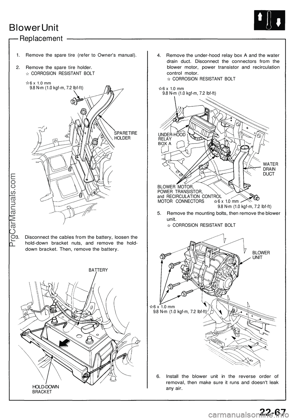
Blower Uni t
Replacemen t
1. Remov e th e spar e tir e (refe r t o Owner' s manual) .
2. Remov e th e spar e tir e holder .
CORROSIO N RESISTAN T BOL T
6 x 1. 0 m m9.8 N- m (1. 0 kgf-m , 7. 2 Ibf-ft )
SPARE TIR E
HOLDE R
3. Disconnec t th e cable s fro m th e battery , loose n th e
hold-dow n bracke t nuts , an d remov e th e hold -
dow n bracket . Then , remov e th e battery .
BATTER Y
HOLD-DOW NBRACKET
4. Remov e th e under-hoo d rela y bo x A an d th e wate r
drai n duct . Disconnec t th e connector s fro m th e
blowe r motor , powe r transisto r an d recirculatio n
contro l motor .
CORROSIO N RESISTAN T BOL T
6 x 1. 0 m m9.8 N- m (1. 0 kgf-m , 7. 2 Ibf-ft )
WATE RDRAINDUCT
BLOWE R MOTOR ,
POWE R TRANSISTOR ,
an d RECIRCULATIO N CONTRO L
MOTOR CONNECTOR S 6 x 1. 0 m m
9. 8 N- m (1. 0 kgf-m , 7. 2 Ibf-ft )
5. Remov e th e mountin g bolts , the n remov e th e blowe r
unit.
CORROSIO N RESISTAN T BOL T
BLOWE RUNIT
6 x 1. 0 m m9.8 N- m (1. 0 kgf-m , 7. 2 Ibf-ft )
6. Instal l th e blowe r uni t i n th e revers e orde r o f
removal , the n mak e sur e i t run s an d doesn' t lea k
any air .
UNDER-HOO DRELAYBOX A
ProCarManuals.com
Page 1206 of 1503
A/C Servic e Tip s an d Precaution s
The ai r conditionin g syste m use s HFC-134 a (R-134a ) refrigeran t and polyalkyleneglyco l (PAG ) refrigeran t oil*, whic h are
not compatibl e wit h CFC-1 2 (R-12 ) refrigeran t an d minera l oil . D o no t us e R-1 2 refrigeran t o r minera l oi l i n thi s system , an d
d o no t attemp t t o us e R-1 2 servicin g equipment ; damag e t o th e ai r conditionin g syste m o r you r servicin g equipmen t wil l result .
*DENS O ND-OIL8 :
• P/N 3889 9 - PR 7 - A01 : 4 0 ( 1 1/ 3 fl-oz , 1. 4 Imp-oz )
• P/ N 38897-PR7-A01AH : 12 0 ( 4 fl-oz , 4. 2 Imp-oz )
Onl y us e servic e equipmen t tha t i s U.L.-liste d an d i s certifie d t o mee t th e requirement s o f SA E J221 0 t o remov e R-134 a
from th e ai r conditione r system .
CAUTION : Exposur e t o ai r conditione r refrigeran t an d lubrican t vapo r o r mis t ca n irritat e eyes , nos e an d throat , Avoi d
breathin g th e ai r conditione r refrigeran t an d lubrican t vapo r o r mist .
I f accidenta l syste m discharg e occurs , ventilat e wor k are a befor e resumin g service .
R-134 a servic e equipmen t o r vehicl e ai r conditione r system s shoul d no t b e pressur e teste d o r lea k teste d wit h compresse d air .
Som e mixture s o f ai r an d R-134 a hav e bee n show n t o b e combustibl e elevate d pressure s an d ca n resul t
i n fir e o r explosio n causin g injur y o r propert y damage . Neve r us e compresse d ai r t o pressur e tes t R-134 a servic e
equipmen t o r vehicl e ai r conditionin g systems .
Additional healt h an d safet y informatio n ma y b e obtaine d fro m th e refrigeran t an d lubrican t manufacturers .
1. Alway s disconnec t th e negativ e cabl e fro m th e batter y wheneve r replacin g ai r conditionin g parts .
2 . Kee p moistur e an d dus t ou t o f th e system . Whe n disconnectin g an y lines , plu g o r ca p th e fitting s immediately ; don' t
remov e th e cap s o r plug s unti l jus t befor e yo u reconnec t eac h line .
3 . Befor e connectin g an y hos e o r line , appl y a fe w drop s o f refrigeran t oi l t o th e O-ring .
4. Whe n tightenin g o r loosenin g a fitting , us e a secon d wrenc h to suppor t th e matchin g fitting .
5. Whe n recoverin g th e system , us e a R-134 a refrigeran t Recovery/Recycling/Chargin g System ; don' t releas e
refrigeran t int o th e atmosphere .
6 . Ad d refrigeran t oi l afte r replacin g th e followin g parts :
NOTE :
• D o no t retur n th e oi l t o th e containe r onc e dispense d an d neve r mi x wit h othe r refrigeran t oil s t o avoi d
contamination .
• Immediatel y afte r usin g th e oil , replac e th e ca p o n th e containe r an d sea l i t t o avoi d moistur e absorption .
• D o no t spil l th e refrigeran t oi l o n th e vehicle ; i t ma y damag e th e paint ; i f th e refrigeran t oi l contact s th e paint , was h
i t of f immediately .
Condense r
............... . 1 0 (1/ 3 fl-oz, 0.4 Imp-oz )
Evaporato r .............. . 1 0 (1/ 3 fl-oz , 0. 4 Imp-oz )
Lin e o r hos e ............ . 2 0 (2/ 3 fl-oz , 0. 7 Imp-oz )
Receive r ................... . 1 0 (1/ 3 fl-oz , 0. 4 Imp-oz )
Compresso r ............ . O n compresso r
replacement , subtrac t th e volum e o f oi l draine d
from th e remove d compresso r fro m 16 0 ( 5 1/ 3
fl-oz , 5. 6 Imp-oz) , an d drai n th e calculate d volum e
of oi l fro m th e ne w compressor : 16 0 ( 5 1/ 3
fl-oz , 5. 6 Imp-oz ) — Volum e o f oi l fro m remove d
compresso r = Volum e t o drai n fro m ne w compres -
sor.
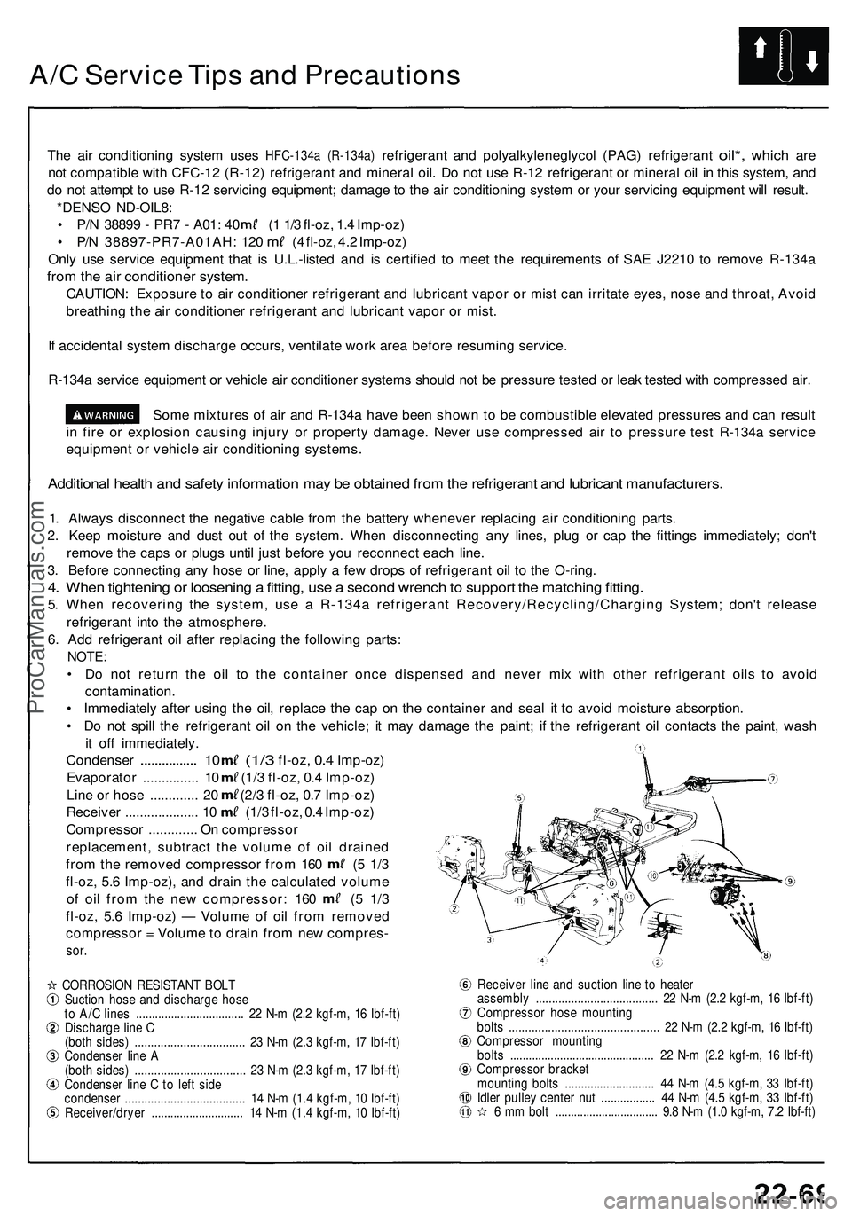
CORROSIO N RESISTAN T BOL T
Suctio n hos e an d discharg e hos e
t o A/ C line s ................................. . 2 2 N- m (2. 2 kgf-m , 1 6 Ibf-ft )
Discharg e lin e C
(bot h sides ) .................................. 23 N- m (2. 3 kgf-m , 1 7 Ibf-ft )
Condense r lin e A
(bot h sides ) ................................. . 2 3 N- m (2. 3 kgf-m , 1 7 Ibf-ft )
Condense r lin e C to lef t sid e
condense r .................................... . 1 4 N- m (1. 4 kgf-m , 1 0 Ibf-ft )
Receiver/drye r ............................ . 1 4 N- m (1. 4 kgf-m , 1 0 Ibf-ft ) Receive
r lin e an d suctio n lin e t o heate r
assembl y ..................................... . 2 2 N- m (2. 2 kgf-m , 1 6 Ibf-ft )
Compresso r hos e mountin g
bolt s ............................................. . 2 2 N- m (2. 2 kgf-m , 1 6 Ibf-ft )
Compresso r mountin g
bolt s ............................................. . 2 2 N- m (2. 2 kgf-m , 1 6 Ibf-ft )
Compresso r bracke t
mountin g bolt s ........................... . 4 4 N- m (4. 5 kgf-m , 3 3 Ibf-ft )
Idle r pulle y cente r nu t ................ . 4 4 N- m (4. 5 kgf-m , 3 3 Ibf-ft )
6 m m bol t ................................ . 9. 8 N- m (1. 0 kgf-m , 7. 2 Ibf-ft )
ProCarManuals.com