fog light ACURA NSX 1997 Service Repair Manual
[x] Cancel search | Manufacturer: ACURA, Model Year: 1997, Model line: NSX, Model: ACURA NSX 1997Pages: 1503, PDF Size: 57.08 MB
Page 64 of 1503
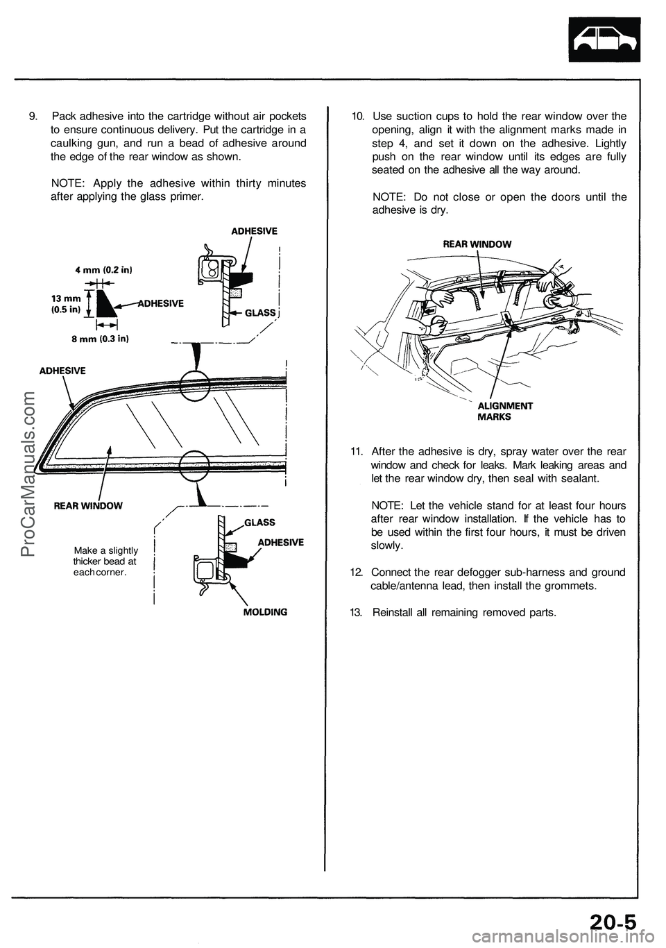
9. Pack adhesive into the cartridge without air pockets
to ensure continuous delivery. Put the cartridge in a
caulking gun, and run a bead of adhesive around
the edge of the rear window as shown.
NOTE: Apply the adhesive within thirty minutes
after applying the glass primer.
Make a slightly
thicker bead at
each corner.
10. Use suction cups to hold the rear window over the
opening, align it with the alignment marks made in
step 4, and set it down on the adhesive. Lightly
push on the rear window until its edges are fully
seated on the adhesive all the way around.
NOTE: Do not close or open the doors until the
adhesive is dry.
11. After the adhesive is dry, spray water over the rear
window and check for leaks. Mark leaking areas and
let the rear window dry, then seal with sealant.
NOTE: Let the vehicle stand for at least four hours
after rear window installation. If the vehicle has to
be used within the first four hours, it must be driven
slowly.
12. Connect the rear defogger sub-harness and ground
cable/antenna lead, then install the grommets.
13. Reinstall all remaining removed parts.ProCarManuals.com
Page 595 of 1503
Idle Contro l Syste m
Alternato r (ALT ) F R Signa l
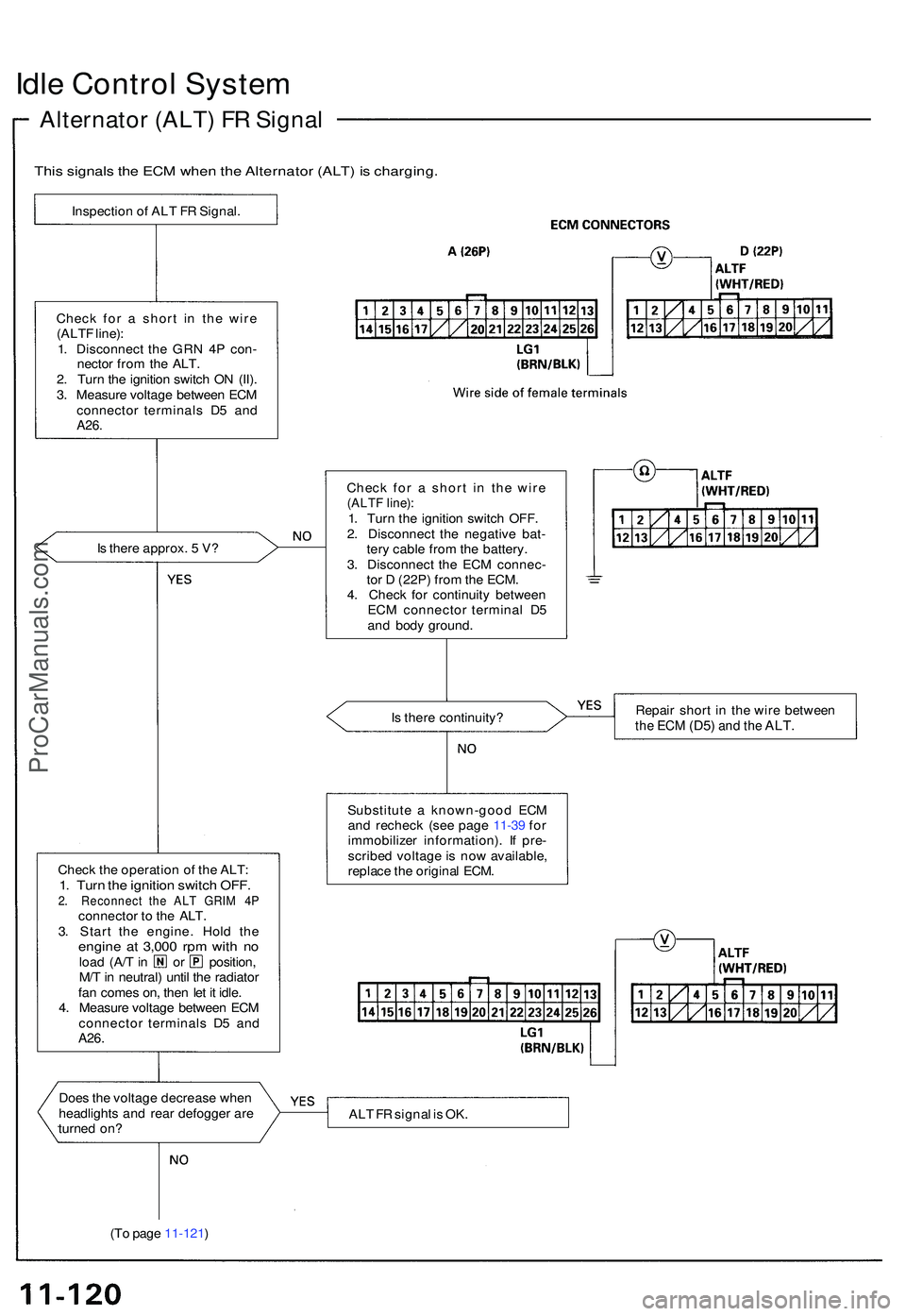
This signal s th e EC M whe n th e Alternato r (ALT ) i s charging .
Inspection o f AL T F R Signal .
Chec k fo r a shor t i n th e wir e
(ALT F line) :
1 . Disconnec t th e GR N 4 P con -
necto r fro m th e ALT .
2 . Tur n th e ignitio n switc h O N (II) .
3 . Measur e voltag e betwee n EC M
connecto r terminal s D 5 an d
A26.
Is ther e approx . 5 V ?
Chec k th e operatio n o f th e ALT :
1. Tur n th e ignitio n switc h OFF .2. Reconnec t th e AL T GRI M 4 Pconnecto r t o th e ALT .
3 . Star t th e engine . Hol d th e
engin e a t 3,00 0 rp m wit h n oloa d (A/ T in o r position ,
M/ T in neutral ) unti l th e radiato r
fa n come s on , the n le t i t idle .
4 . Measur e voltag e betwee n EC M
connecto r terminal s D 5 an d
A26 .
I
Doe s th e voltag e decreas e whe n
headlight s an d rea r defogge r ar e
turne d on ?
(T o pag e 11-121 ) Chec
k fo r a shor t i n th e wir e
(ALT F line) :1. Tur n th e ignitio n switc h OFF .
2 . Disconnec t th e negativ e bat -
ter y cabl e fro m th e battery .
3 . Disconnec t th e EC M connec -
to r D (22P ) fro m th e ECM .
4 . Chec k fo r continuit y betwee n
EC M connecto r termina l D 5
an d bod y ground .
I s ther e continuity ? Repai
r shor t i n th e wir e betwee n
the EC M (D5 ) and th e ALT .
Substitut e a known-goo d EC M
an d rechec k (se e pag e 11-3 9 fo r
immobilize r information) . I f pre -
scribe d voltag e is no w available ,
replac e th e origina l ECM .
AL T F R signa l i s OK .
ProCarManuals.com
Page 604 of 1503
Idle Spee d Settin g
Inspection/Adjustmen t
NOTE : Befor e settin g th e idl e speed , chec k th e thes e
items :
Th e MI L ha s no t bee n reporte d on .
Ignitio n timin g
Spark plug s
Air cleane r
PCV syste m
1 . Star t th e engine . Hol d th e engin e a t 3,00 0 rp m wit h
no loa d (A/ T in o r position , M/ T in neutral ) unti l
th e radiato r fa n come s on , the n tur n th e ignitio n
switch OFF .
2. Connec t th e SC S servic e connecto r t o servic e chec k
connector .
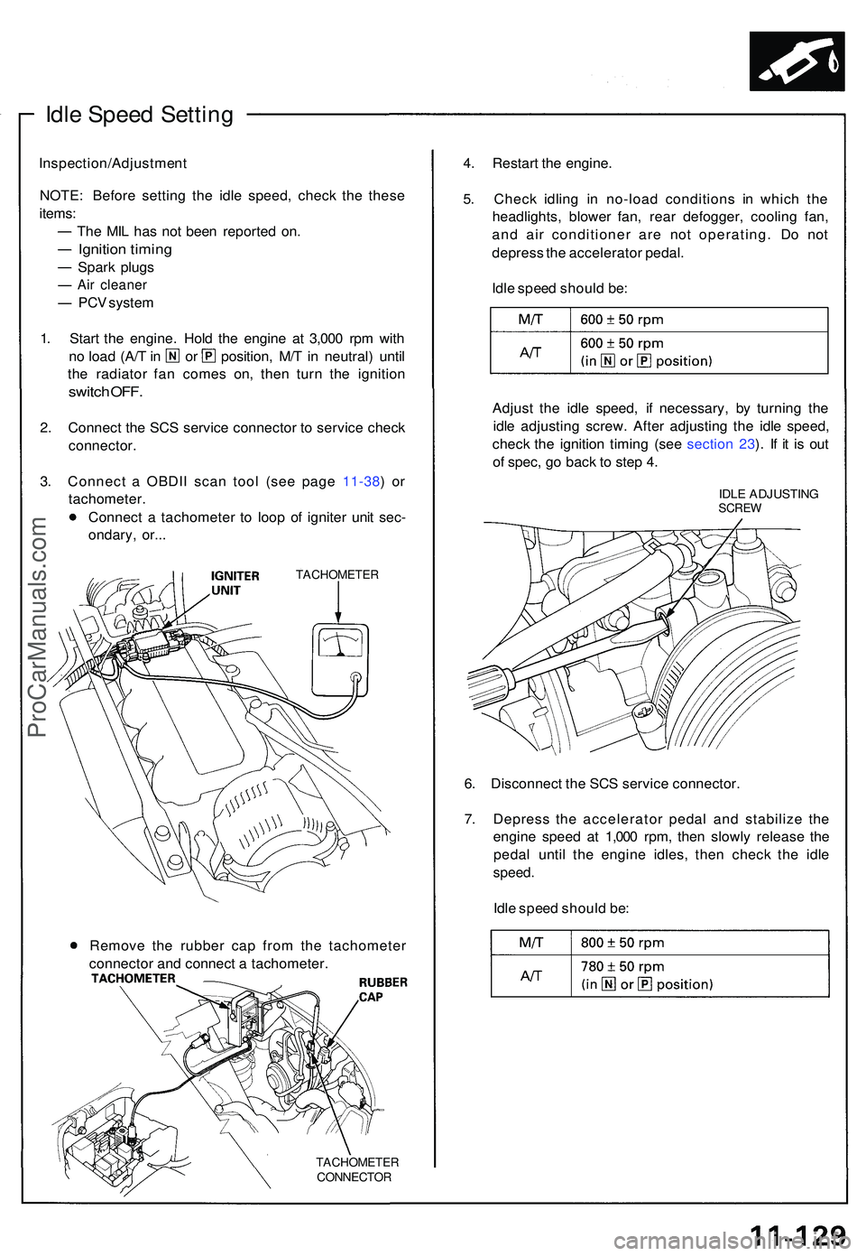
3. Connec t a OBDI I sca n too l (se e pag e 11-38 ) o r
tachometer .
Connec t a tachomete r t o loo p o f ignite r uni t sec -
ondary , or.. .
TACHOMETE R
TACHOMETE R
CONNECTOR
4. Restar t th e engine .
5 . Chec k idlin g i n no-loa d condition s i n whic h th e
headlights , blowe r fan , rea r defogger , coolin g fan ,
an d ai r conditione r ar e no t operating . D o no t
depres s th e accelerato r pedal .
Idl e spee d shoul d be :
Adjus t th e idl e speed , i f necessary , b y turnin g th e
idl e adjustin g screw . Afte r adjustin g th e idl e speed ,
chec k th e ignitio n timin g (se e sectio n 23 ). I f i t i s ou t
o f spec , g o bac k t o ste p 4 .
IDL E ADJUSTIN GSCREW
6. Disconnec t th e SC S servic e connector .
7 . Depres s th e accelerato r peda l an d stabiliz e th e
engin e spee d a t 1,00 0 rpm , the n slowl y releas e th e
peda l unti l th e engin e idles , the n chec k th e idl e
speed .
Idle spee d shoul d be :
Remov e th e rubbe r ca p fro m th e tachomete r
connecto r an d connec t a tachometer .
ProCarManuals.com
Page 632 of 1503
Emission Contro l Syste m
System Descriptio n
The emissio n contro l syste m include s tw o Thre e Wa y
Catalyti c Converter s (TWCs) , Exhaus t Ga s Recirculatio n
(EGR ) system , Positiv e Crankcas e Ventilatio n (PCV ) sys -
te m an d Evaporativ e Emissio n (EVAP ) Contro l system .
Th e emissio n contro l syste m is designe d t o mee t federa l
an d stat e emissio n standards .
Tailpipe Emissio n
1. Star t th e engine . Hol d th e engine at 3,00 0 rp m wit h
no loa d (A/ T in o r position , M/ T in neutral ) unti l
th e radiato r fa n come s on , the n le t i t idle .
2 . Connec t a tachometer .
3 . Chec k an d adjus t th e idl e speed , i f necessar y (se e
pag e 11-129 ).
4 . War m u p an d calibrat e th e C O mete r accordin g t o
th e mete r manufacturer' s instructions .
5 . Chec k idl e C O wit h th e headlights , heate r blower ,
rea r windo w defogger , coolin g fan , an d ai r condi -
tione r off .
NOTE : (Canada ) Pul l th e parkin g brak e leve r up .
Star t th e engine , the n chec k tha t th e headlight s ar e
off.
CO mete r shoul d indicat e 0.1 % maximum .
Inspection
any ope n flam e awa y fro m you r wor k area .
D
o no t smok e durin g thi s procedure . Kee p
ProCarManuals.com
Page 1089 of 1503
Rear Window
Installation (cont'd)
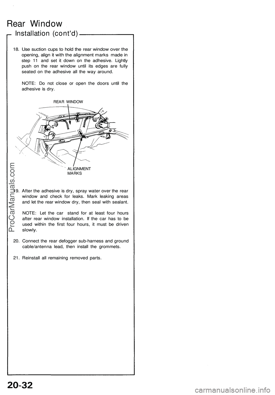
18. Use suction cups to hold the rear window over the
opening, align it with the alignment marks made in
step 11 and set it down on the adhesive. Lightly
push on the rear window until its edges are fully
seated on the adhesive all the way around.
NOTE: Do not close or open the doors until the
adhesive is dry.
REAR WINDOW
ALIGNMENT
MARKS
19. After the adhesive is dry, spray water over the rear
window and check for leaks. Mark leaking areas
and let the rear window dry, then seal with sealant.
NOTE: Let the car stand for at least four hours
after rear window installation. If the car has to be
used within the first four hours, it must be driven
slowly.
20. Connect the rear defogger sub-harness and ground
cable/antenna lead, then install the grommets.
21. Reinstall all remaining removed parts.ProCarManuals.com
Page 1323 of 1503
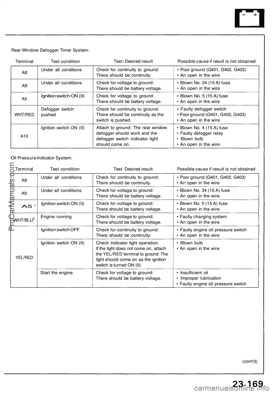
Rear Window Defogger Timer System:
Terminal Test condition
Test: Desired result
Possible cause if result is not obtained
A8
A9
A5
WHT/RED
A10
Under all conditions
Under all conditions
Ignition switch ON (II)
Defogger switch
pushed
Ignition switch ON (II)
Check for continuity to ground:
There should be continuity.
Check for voltage to ground:
There should be battery voltage.
Check for voltage to ground:
There should be battery voltage.
Check for continuity to ground:
There should be continuity as the
switch is pushed.
Attach to ground: The rear window
defogger should work and the
defogger switch indicator light
should come on.
• Poor ground (G401, G402, G403)
• An open in the wire
• Blown No. 34 (15 A) fuse
• An open in the wire
• Blown No. 5 (15 A) fuse
• An open in the wire
• Faulty defogger switch
• Poor ground (G401, G402, G403)
• An open in the wire
• Blown No. 4 (15 A) fuse
• Faulty defogger relay
• Blown bulb
• An open in the wire
Oil Pressure Indicator System:
Terminal Test condition
Test: Desired result
Possible cause if result is not obtained
A8
A9
A5 '
WHT/BLU2
YEL/RED
Under all conditions
Under all conditions
Ignition switch ON (II)
Engine running
Ignition switch OFF
Ignition switch ON (II)
Start the engine.
Check for continuity to ground:
There should be continuity.
Check for voltage to ground:
There should be battery voltage.
Check for voltage to ground:
There should be battery voltage.
Check for voltage to ground:
There should be battery voltage.
Check for continuity to ground:
There should be continuity.
Check indicator light operation.
If the light does not come on, attach
the YEL/RED terminal to ground: The
light should come on as the ignition
switch is turned ON (II).
Check for voltage to ground:
There should be battery voltage.
• Poor ground (G401, G402, G403)
• An open in the wire
• Blown No. 34 (15 A) fuse
• An open in the wire
• Blown No. 5 (15 A) fuse
• An open in the wire
• Faulty charging system
• An open in the wire
• Faulty engine oil pressure switch
• An open in the wire
• Blown bulb
• An open in the wire
• Insufficient oil
• Improper lubrication
• Faulty engine oil pressure switch
(cont'd)ProCarManuals.com
Page 1427 of 1503
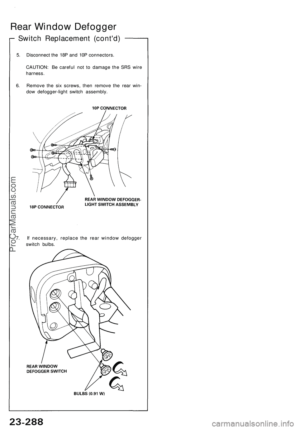
Switch Replacement (cont'd)
Rear Window Defogger
5. Disconnect the 18P and 10P connectors.
CAUTION: Be careful not to damage the SRS wire
harness.
6. Remove the six screws, then remove the rear win-
dow defogger-light switch assembly.
7. If necessary, replace the rear window defogger
switch bulbs.ProCarManuals.com
Page 1430 of 1503
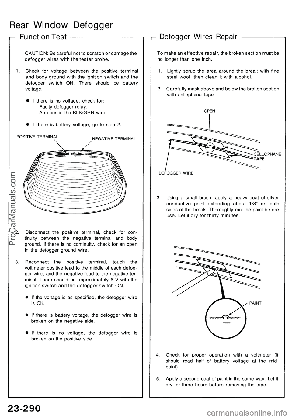
Rear Window Defogger
Function Test
CAUTION: Be careful not to scratch or damage the
defogger wires with the tester probe.
Check for voltage between the positive terminal
and body ground with the ignition switch and the
defogger switch ON. There should be battery
voltage.
If there is no voltage, check for:
— Faulty defogger relay.
— An open in the BLK/GRN wire.
If there is battery voltage, go to step 2.
POSITIVE TERMINAL
NEGATIVE TERMINAL
2. Disconnect the positive terminal, check for con-
tinuity between the negative terminal and body
ground. If there is no continuity, check for an open
in the defogger ground wire.
3. Reconnect the positive terminal, touch the
voltmeter positive lead to the middle of each defog-
ger wire, and the negative lead to the negative ter-
minal. There should be approximately 6 V with the
ignition switch and the defogger switch ON.
If the voltage is as specified, the defogger wire
is OK.
If there is battery voltage, the defogger wire is
broken on the negative side.
If there is no voltage, the defogger wire is
broken on the positive side.
Defogger Wires Repair
To make an effective repair, the broken section must be
no longer than one inch.
1. Lightly scrub the area around the break with fine
steel wool, then clean it with alcohol.
2. Carefully mask above and below the broken section
with cellophane tape.
OPEN
CELLOPHANE
DEFOGGER WIRE
3. Using a small brush, apply a heavy coat of silver
conductive paint extending about 1/8" on both
sides of the break. Thoroughly mix the paint before
use. Let it dry for thirty minutes.
PAINT
4. Check for proper operation with a voltmeter (it
should read half of battery voltage at the mid-
point).
5. Apply a second coat of paint in the same way. Let it
dry for three hours before removing the tape.ProCarManuals.com