oil level ACURA NSX 1997 Service Repair Manual
[x] Cancel search | Manufacturer: ACURA, Model Year: 1997, Model line: NSX, Model: ACURA NSX 1997Pages: 1503, PDF Size: 57.08 MB
Page 32 of 1503
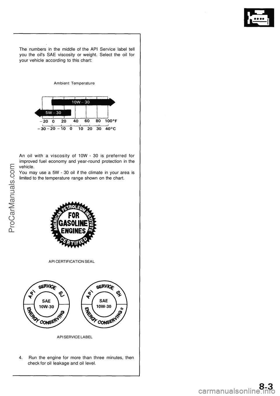
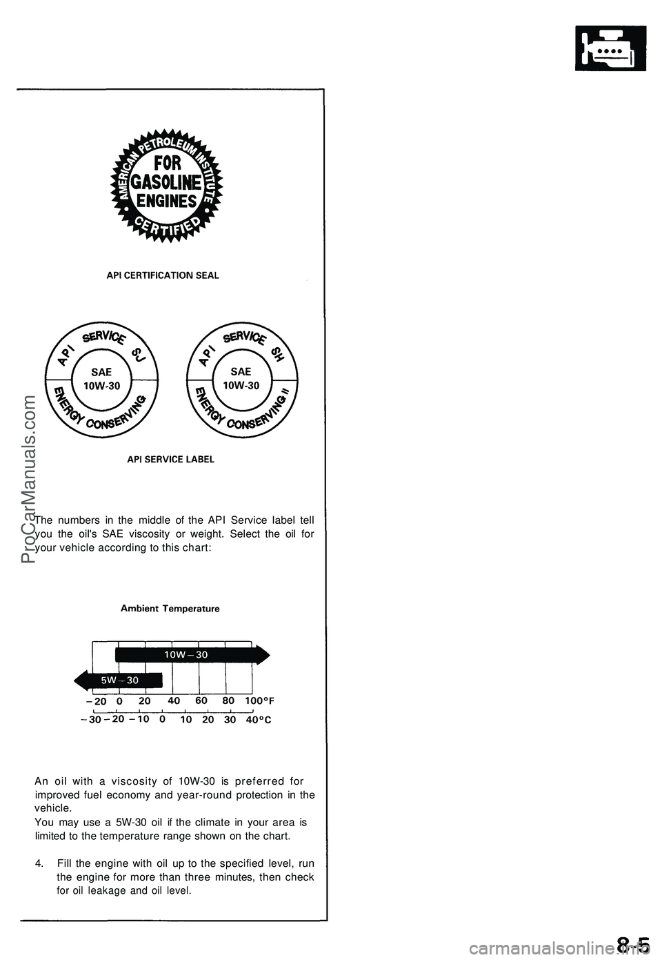
The numbers in the middle of the API Service label tell
you the oil's SAE viscosity or weight. Select the oil for
your vehicle according to this chart:
Ambient Temperature
An oil with a viscosity of 10W - 30 is preferred for
improved fuel economy and year-round protection in the
vehicle.
You may use a 5W - 30 oil if the climate in your area is
limited to the temperature range shown on the chart.
API CERTIFICATION SEAL
API SERVICE LABEL
4. Run the engine for more than three minutes, then
check for oil leakage and oil level.ProCarManuals.com
Page 374 of 1503
4-5
Y
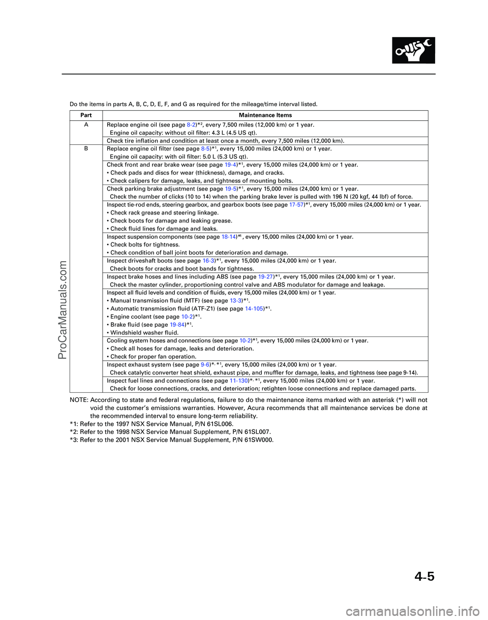
Do the items in parts A, B, C, D, E, F, and G as required for the mileag\
e/time interval listed.
NOTE: According to state and federal regulations, failure to do the maintenanc\
e items marked with an asterisk (*) will not
void the customer ’s emissions warranties. However, Acura recommends that all maintenance s\
ervices be done at
the recommended interval to ensure long-term reliability.
*1: Refer to the 1997 NSX Service Manual, P/N 61SL006.
*2: Refer to the 1998 NSX Service Manual Supplement, P/N 61SL007.
*3: Refer to the 2001 NSX Service Manual Supplement, P/N 61SW000.
A
B Replace engine oil (see page
8-2)*
2, every 7,500 miles (12,000 km) or 1 year.
Engine oil capacity: without oil filter: 4.3 L (4.5 US qt).
Check tire inflation and condition at least once a month, every 7,500 mi\
les (12,000 km).
Replace engine oil filter (see page 8-5)*1, every 15,000 miles (24,000 km) or 1 year.
Engine oil capacity: with oil filter: 5.0 L (5.3 US qt).
Check front and rear brake wear (see page 19-4)*1, every 15,000 miles (24,000 km) or 1 year.
• Check pads and discs for wear (thickness), damage, and cracks.
• Check calipers for damage, leaks, and tightness of mounting bolts.
Check parking brake adjustment (see page 19-5)*1, every 15,000 miles (24,000 km) or 1 year.
Check the number of clicks (10 to 14) when the parking brake lever is pulled with 196 N (20 kgf,\
44 lbf) of force.
Inspect tie-rod ends, steering gearbox, and gearbox boots (see page 17-57)*1, every 15,000 miles (24,000 km) or 1 year.
• Check rack grease and steering linkage.
• Check boots for damage and leaking grease.
• Check fluid lines for damage and leaks.1
• Check bolts for tightness.
• Check condition of ball joint boots for deterioration and damage.
Inspect driveshaft boots (see page 16-3)*1, every 15,000 miles (24,000 km) or 1 year.
Check boots for cracks and boot bands for tightness.
Inspect brake hoses and lines including ABS (see page 19-27)*1, every 15,000 miles (24,000 km) or 1 year.
Check the master cylinder, proportioning control valve and ABS modulator\
for damage and leakage.
Inspect all fluid levels and condition of fluids, every 15,000 miles (2\
4,000 km) or 1 year.
• Manual transmission fluid (MTF) (see page 13-3)*
1.
• Automatic transmission fluid (ATF-Z1) (see page 14-105)*1.
• Engine coolant (see page 10-2)*1.
• Brake fluid (see page 19-84)*1.
• Windshield washer fluid.
Cooling system hoses and connections (see page 10-2)*1, every 15,000 miles (24,000 km) or 1 year.
• Check all hoses for damage, leaks and deterioration.
• Check for proper fan operation.
Inspect exhaust system (see page 9-6)*, *1, every 15,000 miles (24,000 km) or 1 year.
Check catalytic converter heat shield, exhaust pipe, and muffler for dam\
age, leaks, and tightness ( see page 9-14 ).
Inspect fuel lines and connections (see page 11-130)*, *1, every 15,000 miles (24,000 km) or 1 year.
Check for loose connections, cracks, and deterioration; retighten loose \
connections and replace damaged parts.
Part Maintenance Items
*05-NSX (61SW004)SEC04(01-10) 9/22/04 1:49 PM Page 4-5
Inspect suspension components (see page 18-14)* , every 15,000 miles (24,000 km) or 1 year.
ProCarManuals.com
Page 472 of 1503
Camshafts
Installation (cont'd)
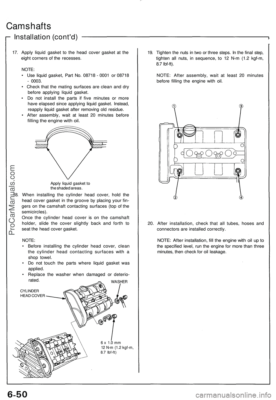
17. Apply liquid gasket to the head cover gasket at the
eight corners of the recesses.
NOTE:
• Use liquid gasket, Part No. 08718 - 0001 or 08718
- 0003.
• Check that the mating surfaces are clean and dry
before applying liquid gasket.
• Do not install the parts if five minutes or more
have elapsed since applying liquid gasket. Instead,
reapply liquid gasket after removing old residue.
• After assembly, wait at least 20 minutes before
filling the engine with oil.
Apply liquid gasket to
the shaded areas.
18. When installing the cylinder head cover, hold the
head cover gasket in the groove by placing your fin-
gers on the camshaft contacting surfaces (top of the
semicircles).
Once the cylinder head cover is on the camshaft
holder, slide the cover slightly back and forth to
seat the head cover gasket.
NOTE:
• Before installing the cylinder head cover, clean
the cylinder head contacting surfaces with a
shop towel.
• Do not touch the parts where liquid gasket was
applied.
• Replace the washer when damaged or deterio-
rated.
CYLINDER
HEAD COVER
WASHER
6 x 1.0 mm
12 N-m (1.2 kgf-m,
8.7 Ibf-ft)
19. Tighten the nuts in two or three steps. In the final step,
tighten all nuts, in sequence, to 12 N-m (1.2 kgf-m,
8.7 Ibf-ft).
NOTE: After assembly, wait at least 20 minutes
before filling the engine with oil.
20. After installation, check that all tubes, hoses and
connectors are installed correctly.
NOTE: After installation, fill the engine with oil up to
the specified level, run the engine for more than three
minutes, then check for oil leakage.ProCarManuals.com
Page 501 of 1503
Engine Oil
Inspection
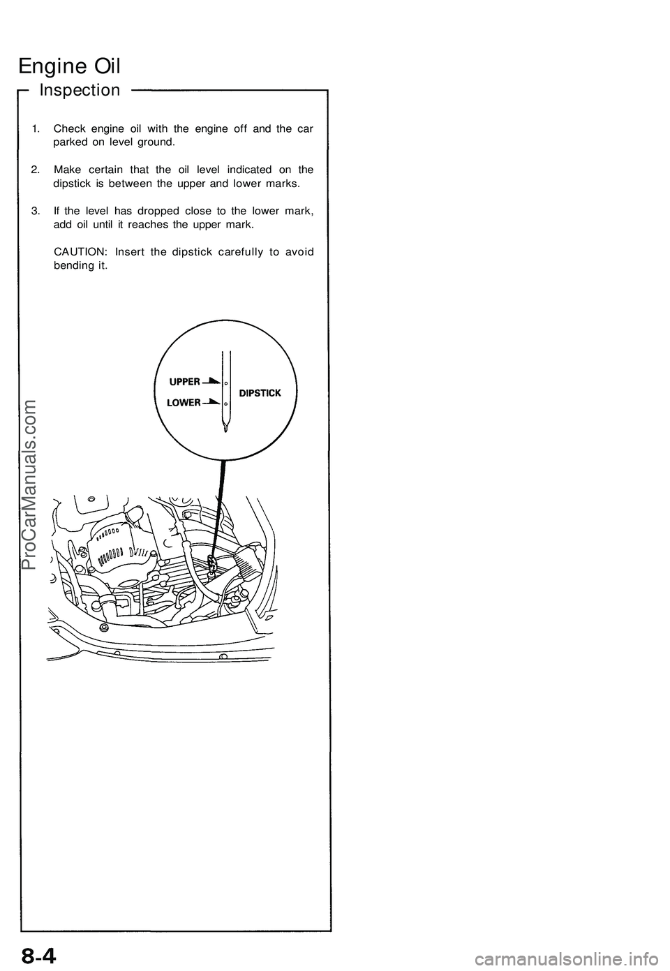
1. Check engine oil with the engine off and the car
parked on level ground.
2. Make certain that the oil level indicated on the
dipstick is between the upper and lower marks.
3. If the level has dropped close to the lower mark,
add oil until it reaches the upper mark.
CAUTION: Insert the dipstick carefully to avoid
bending it.ProCarManuals.com
Page 503 of 1503
The number s i n th e middl e o f th e AP I Servic e labe l tel l
yo u th e oil' s SA E viscosit y o r weight . Selec t th e oi l fo r
you r vehicl e accordin g t o thi s chart :
A n oi l wit h a viscosit y o f 10 W-3 0 i s preferre d fo r
improve d fue l econom y an d year-roun d protection in th e
vehicle .
Yo u ma y us e a 5 W-3 0 oi l i f th e climat e i n you r are a i s
limite d t o th e temperatur e rang e show n o n th e chart .
4 . Fil l th e engin e wit h oi l u p t o th e specifie d level , ru n
th e engin e fo r mor e tha n thre e minutes , the n chec k
for oi l leakag e an d oi l level .
ProCarManuals.com
Page 505 of 1503
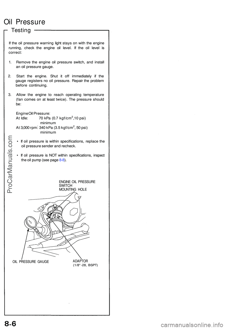
Oil Pressur e
Testing
If th e oi l pressur e warnin g ligh t stay s o n wit h th e engin e
running , chec k th e engin e oi l level . I f th e oi l leve l i s
correct :
1 . Remov e th e engine oil pressur e switch , an d instal l
a n oi l pressur e gauge .
2 . Star t th e engine . Shu t i t of f immediatel y i f th e
gaug e register s n o oi l pressure . Repai r th e proble m
before continuing .
3. Allo w th e engin e t o reac h operatin g temperatur e
(fa n come s o n a t leas t twice) . Th e pressur e shoul d
be:
Engin e Oi l Pressure :
A t Idle : 7 0 kP a (0. 7 kgf/cm2,1 0 psi )
minimu m
A t 3,00 0 rpm : 34 0 kP a (3. 5 kgf/cm
2, 5 0 psi )
minimu m
• I f oi l pressur e i s withi n specifications , replac e th e
oi l pressur e sende r an d recheck .
• I f oi l pressur e i s NO T withi n specifications , inspec t
th e oi l pum p (se e pag e 8-8 ).
ENGIN E OI L PRESSUR ESWITCHMOUNTIN G HOL E
OIL PRESSUR E GAUG EADAPTO R(1/8"-28, BSPT )
ProCarManuals.com
Page 652 of 1503
Maintenance
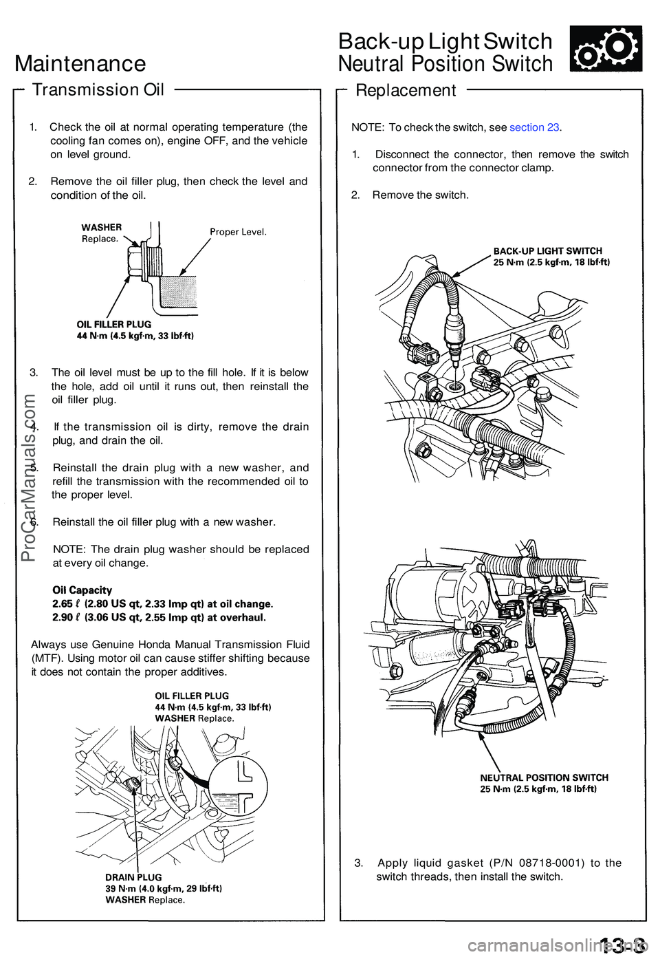
Transmissio n Oi l
1. Chec k th e oi l a t norma l operating temperatur e (th e
coolin g fa n come s on) , engin e OFF , an d th e vehicl e
o n leve l ground .
2 . Remov e th e oi l fille r plug , the n chec k th e leve l an d
conditio n o f th e oil .
3. Th e oi l leve l mus t b e u p t o th e fil l hole . I f i t i s belo w
th e hole , ad d oi l unti l i t run s out , the n reinstal l th e
oi l fille r plug .
4 . I f th e transmissio n oi l i s dirty , remov e th e drai n
plug , an d drai n th e oil .
5 . Reinstal l th e drai n plu g wit h a ne w washer , an d
refil l th e transmissio n wit h th e recommende d oi l t o
th e prope r level .
6 . Reinstal l th e oi l fille r plu g wit h a ne w washer .
NOTE : Th e drai n plu g washe r shoul d b e replace d
a t ever y oi l change .
Back-up Ligh t Switc h
Neutra l Positio n Switc h
Replacemen t
NOTE: T o chec k th e switch , se e sectio n 23 .
1 . Disconnec t th e connector , the n remov e th e switc h
connecto r fro m th e connecto r clamp .
2 . Remov e th e switch .
3 . Appl y liqui d gaske t (P/ N 0871 8-0001 ) t o th e
switc h threads , the n instal l th e switch .
Alway
s us e Genuin e Hond a Manua l Transmissio n Flui d
(MTF) . Usin g moto r oi l ca n caus e stiffe r shiftin g becaus e
i t doe s no t contai n th e prope r additives .
ProCarManuals.com
Page 1261 of 1503
Description ——————————————————\
——————————————————\
———
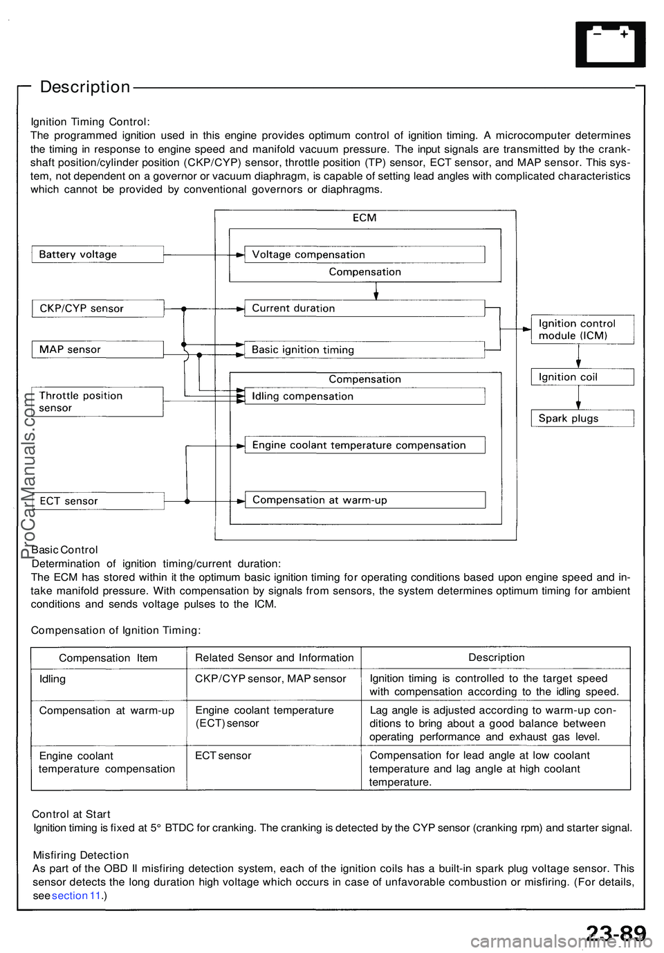
Ignition Timin g Control :
Th e programme d ignitio n use d i n thi s engin e provide s optimu m contro l o f ignitio n timing . A microcompute r determine s
th e timin g i n respons e t o engin e spee d an d manifol d vacuu m pressure . Th e inpu t signal s ar e transmitte d b y th e crank -
shaf t position/cylinde r positio n (CKP/CYP ) sensor , throttl e positio n (TP ) sensor , EC T sensor , an d MA P sensor . Thi s sys -
tem , no t dependen t o n a governo r o r vacuu m diaphragm , i s capabl e o f settin g lea d angle s wit h complicate d characteristic s
whic h canno t b e provide d b y conventiona l governor s o r diaphragms .
Basi c Contro l
Determinatio n of ignitio n timing/curren t duration :
Th e EC M ha s store d withi n i t th e optimu m basi c ignitio n timin g fo r operatin g condition s base d upo n engin e spee d an d in -
tak e manifol d pressure . Wit h compensatio n b y signal s fro m sensors , th e syste m determine s optimu m timin g fo r ambien t
condition s an d send s voltag e pulse s t o th e ICM .
Compensatio n o f Ignitio n Timing :
Compensatio n Ite m
Idlin g
Compensatio n a t warm-u p
Engin e coolan t
temperatur e compensatio nRelate
d Senso r an d Informatio n
CKP/CY P sensor , MA P senso r
Engin e coolan t temperatur e
(ECT) senso r
ECT senso r Descriptio
n
Ignitio n timin g i s controlle d t o th e targe t spee d
wit h compensatio n accordin g t o th e idlin g speed .
La g angl e i s adjuste d accordin g t o warm-u p con -
dition s t o brin g abou t a goo d balanc e betwee n
operatin g performanc e an d exhaus t ga s level .
Compensatio n fo r lea d angl e a t low coolan t
temperatur e an d la g angl e a t hig h coolan t
temperature .
Contro l a t Star t
Ignitio n timin g is fixe d a t 5 ° BTD C fo r cranking . Th e crankin g is detecte d b y th e CY P senso r (crankin g rpm ) an d starte r signal .
Misfirin g Detectio n
A s par t o f th e OB D II misfirin g detectio n system , eac h o f th e ignitio n coil s ha s a built-i n spar k plu g voltag e sensor . Thi s
senso r detect s th e lon g duratio n hig h voltag e whic h occur s i n cas e o f unfavorabl e combustio n o r misfiring . (Fo r details ,
se e sectio n 11 .)
ProCarManuals.com