oil temperature ACURA NSX 1997 Service Repair Manual
[x] Cancel search | Manufacturer: ACURA, Model Year: 1997, Model line: NSX, Model: ACURA NSX 1997Pages: 1503, PDF Size: 57.08 MB
Page 32 of 1503
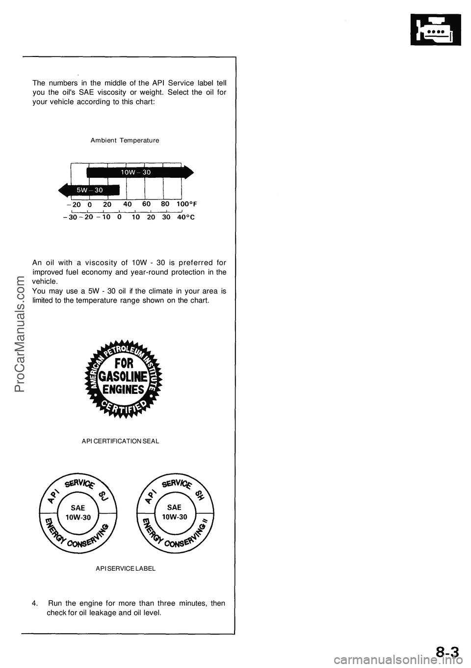
The numbers in the middle of the API Service label tell
you the oil's SAE viscosity or weight. Select the oil for
your vehicle according to this chart:
Ambient Temperature
An oil with a viscosity of 10W - 30 is preferred for
improved fuel economy and year-round protection in the
vehicle.
You may use a 5W - 30 oil if the climate in your area is
limited to the temperature range shown on the chart.
API CERTIFICATION SEAL
API SERVICE LABEL
4. Run the engine for more than three minutes, then
check for oil leakage and oil level.ProCarManuals.com
Page 369 of 1503
3-14
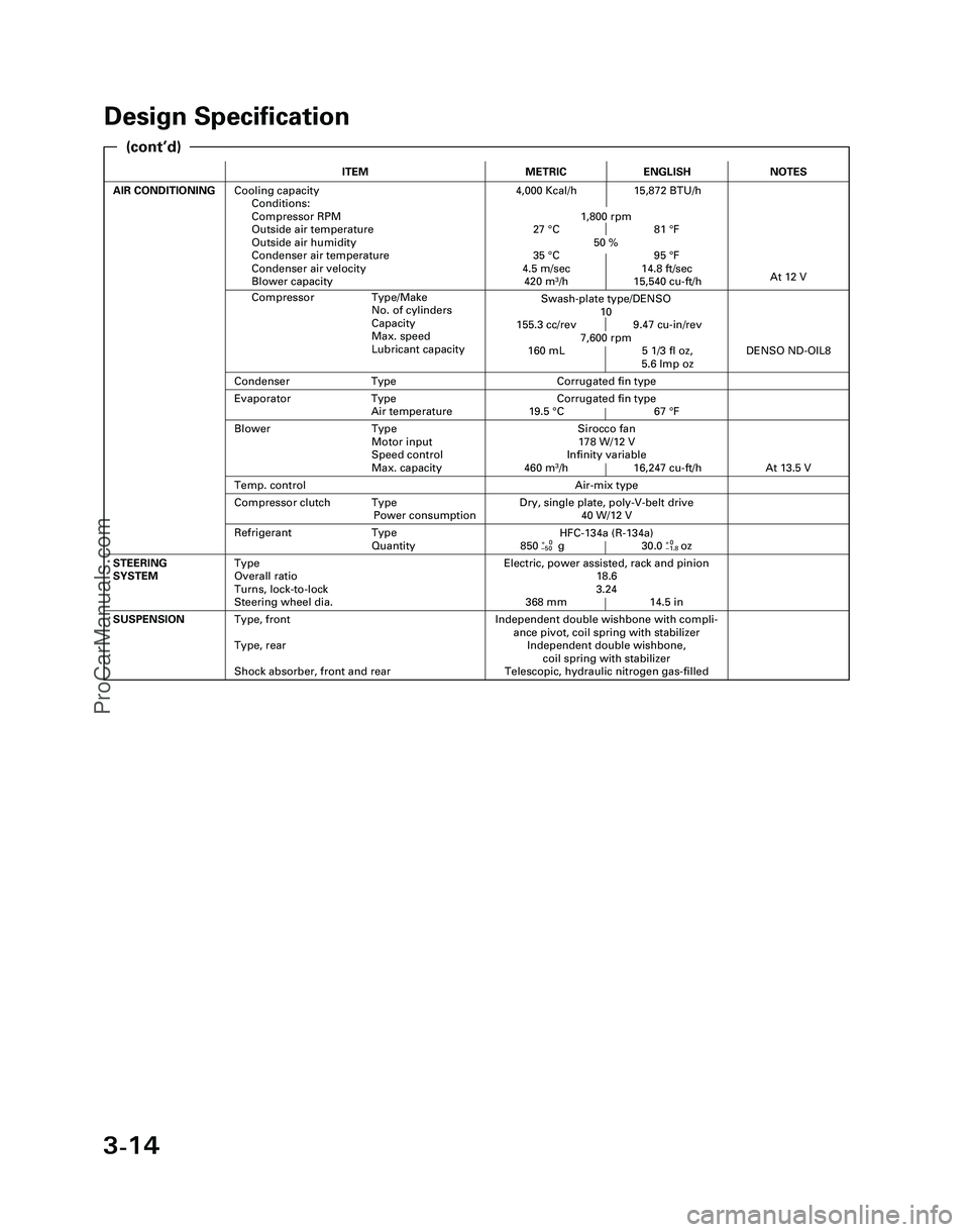
Design Specification
ITEMMETRICENGLISH
AIR CONDITIONINGCooling capacity
Conditions:
Compressor RPM
Outside air temperature
Outside air humidity
Condenser air temperature
Condenser air velocity
Blower capacity4,000 Kcal/h 15,872 BTU/h
1,800 rpm
27 °C 81 °F
50 %
35 °C 95 °F
4.5 m/sec 14.8 ft/sec
420 m
3/h 15,540 cu-ft/h
Independent double wishbone with compli-
ance pivot, coil spring with stabilizer
Independent double wishbone,
coil spring with stabilizer
Telescopic, hydraulic nitrogen gas-filledSUSPENSIONType, front
Type, rear
Shock absorber, front and rear
Evaporator Type
Air temperatureCorrugated fin type
19.5 °C 67 °F
Compressor Type/Make
No. of cylinders
Capacity
Max. speed
Lubricant capacity
NOTES
Swash-plate type/DENSO
10
155.3 cc/rev 9.47 cu-in/rev
7,600 rpm
160 mL 5 1/3 fl oz,
5.6 lmp oz
At 12 V
Air-mix type
Sirocco fan
178 W/12 V
Infinity variable
460 m
3/h 16,247 cu-ft/h
DENSO ND-OIL8
Condenser TypeCorrugated fin type
Temp. control
Blower Type
Motor input
Speed control
Max. capacity
At 13.5 V
Refrigerant Type
Quantity
Dry, single plate, poly-V-belt drive
40 W/12 VCompressor clutch Type
Power consumption
Electric, power assisted, rack and pinion
18.6
3.24
368 mm 14.5 inSTEERING
SYSTEMType
Overall ratio
Turns, lock-to-lock
Steering wheel dia.
HFC-134a (R-134a)
850+0g 30.0+0oz–50–1.8
(cont’d)
*04-NSX (61SW004)SEC03(01-16) 9/22/04 1:49 PM Page 3-14
ProCarManuals.com
Page 371 of 1503
4-2
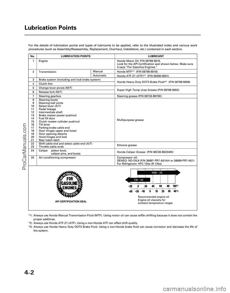
For the details of lubrication points and types of lubricants to be appl\
ied, refer to the illustrated index and various work
procedures (such as Assembly/Reassembly, Replacement, Overhaul, Install\
ation, etc.) contained in each section.
*1: Always use Honda Manual Transmission Fluid (MTF). Using motor oil can \
cause stiffer shifting because it does not contain theproper additives.
*2: Always use Honda ATF-Z1 (ATF). Using a non-Honda ATF can affect shift \
quality.
*3: Always use Honda Heavy Duty DOT3 Brake Fluid. Using a non-Honda brake fl\
uid can cause corrosion and decrease the life of the system.
Lubrication Points
No.LUBRICATION POINTSLUBRICANT
1Honda Motor Oil: P/N 08798-9015.
Look for the API Certification seal shown below. Make sure
it says “For Gasoline Engines.”
2TransmissionHonda MTF*1(P/N 08798-9016)
3Brake system (including anti-lock brake system)Honda Heavy Duty DOT3 Brake Fluid*3(P/N 08798-9008)4Clutch line
5Change lever pivots (M/T)Super High Temp Urea Grease (P/N 08798-9002)6Release fork (M/T)
8
9
10
11
12
13
14
15
16
17
18
19
20
21Steering boots
Steering ball joints
Select lever (A/T)
Pedal linkage
Intermediate shaft
Brake master power pushrod
Fuel fill door
Clutch master cylinder pushrod
Tilt lever
Parking brake cable end
Door hinges upper and lower
Door opening detents
Hood hinges and lock
Rear hatch latch
Multipurpose grease
24
22
23
Caliper piston boot, caliper pins, and boots
Shift cable end and select cable end (A/T)
Throttle cable ends
Honda Caliper Grease (P/N 08C30-B0234M)
Silicone grease
25Air conditioning compressorCompressor oil:
DENSO: ND-OIL8 (P/N 38897-PR7-A01AH or 38899-PR7-A01)
For Refrigerant: HFC-134a (R-134a)
Manual
Honda ATF-Z1 (ATF)*2(P/N 08200-9001)Automatic
7Steering gearboxSteering grease (P/N 08733-B070E)
Engine
API CERTIFICATION SEAL
Recommended engine oil
Engine oil viscosity for
ambient temperature ranges
*05-NSX (61SW004)SEC04(01-10) 9/22/04 1:49 PM Page 4-2
ProCarManuals.com
Page 432 of 1503
Removal
NOTE:
• Befor e removin g th e belt , tur n th e crankshaf t pulle y
s o th e No . 1 pisto n i s a t to p dea d cente r (TDC ) (se e
pag e 6-19 ).
• Inspec t th e wate r pum p afte r removin g th e timin g
bel t (se e pag e 10-11 ).
• I f i t i s t o b e reused , mar k th e directio n o f rotatio n o n
th e belt .
• Replac e th e timin g bel t a t 105,00 0 mile s (168,00 0 km )
accordin g t o th e maintenanc e schedul e (norma l con -
ditions/sever e conditions) . I f th e vehicl e i s regularl y
driven i n on e o r mor e o f th e followin g conditions ,
replace th e timin g bel t a t 60,00 0 mile s (U.S.A. )
100,00 0 k m (Canada) .
— In ver y hig h temperature s (ove r 110°F , 43°C) .
— In ver y lo w temperature s (unde r -20°F , -29°C) .
1 . Disconnec t th e batter y negativ e termina l first , the n
th e positiv e terminal .
2 . Remov e th e righ t rea r wheel/tire .
3 . Remov e th e engin e oi l coole r bas e assembly .
NOTE : D o no t disconnec t th e hoses .
O-RINGReplace .
4. Remov e th e stru t brac e (se e pag e 5-3 ).
5 . Remov e th e intak e manifol d plat e an d to p cove r (se e
pag e 6-26 ). 4
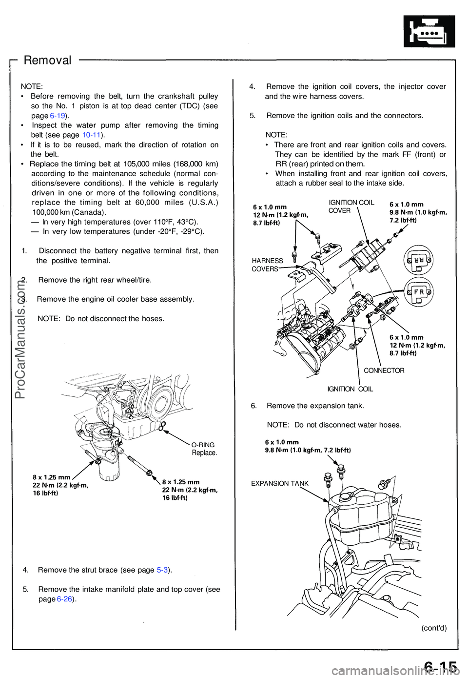
. Remov e th e ignitio n coi l covers , th e injecto r cove r
an d th e wir e harnes s covers .
5 . Remov e th e ignitio n coil s an d th e connectors .
NOTE:
• Ther e ar e fron t an d rea r ignitio n coil s an d covers .
The y ca n b e identifie d b y th e mar k F F (front ) o r
RR (rear ) printe d o n them .
• Whe n installin g fron t an d rea r ignitio n coi l covers ,
attac h a rubbe r sea l t o th e intak e side .
HARNES SCOVERS
IGNITION COI LCOVE R
CONNECTO R
IGNITION COI L
6. Remov e th e expansio n tank .
NOTE : D o no t disconnec t wate r hoses .
EXPANSIO N TAN K
(cont'd )
ProCarManuals.com
Page 438 of 1503
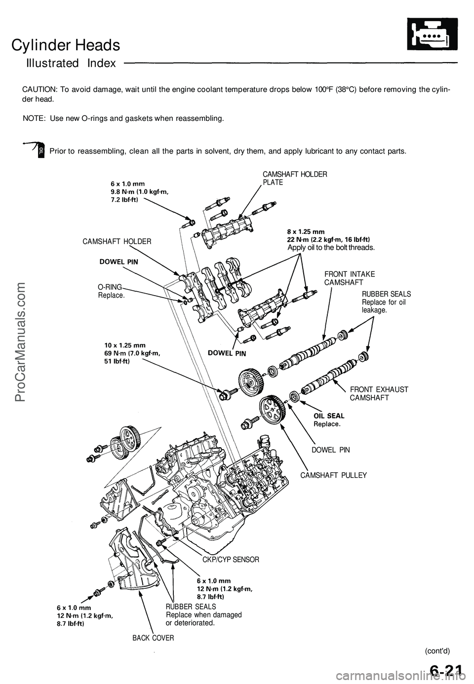
Cylinder Heads
Illustrated Index
CAUTION: To avoid damage, wait until the engine coolant temperature drops below 100°F (38°C) before removing the cylin-
der head.
NOTE: Use new O-rings and gaskets when reassembling.
Prior to reassembling, clean all the parts in solvent, dry them, and apply lubricant to any contact parts.
CAMSHAFT HOLDER
O-RING
Replace.
CAMSHAFT HOLDER
PLATE
CKP/CYP SENSOR
RUBBER SEALS
Replace when damaged
or deteriorated.
BACK COVER
Apply oil to the bolt threads.
FRONT INTAKE
CAMSHAFT
RUBBER SEALS
Replace for oil
leakage.
FRONT EXHAUST
CAMSHAFT
DOWEL PIN
CAMSHAFT PULLEY
(cont'd)ProCarManuals.com
Page 498 of 1503
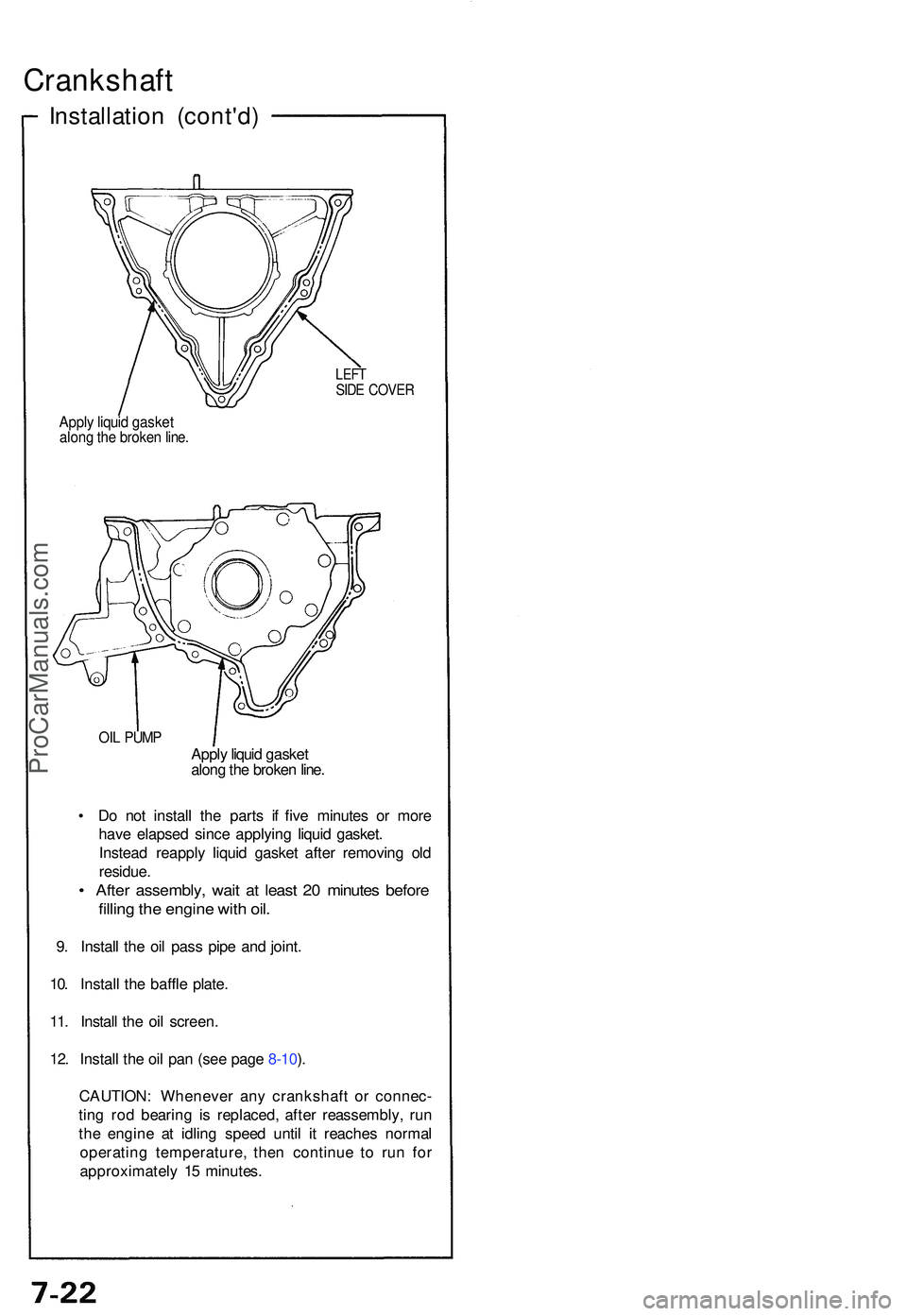
Crankshaft
Installation (cont'd )
LEFTSIDE COVE R
Apply liqui d gaske talong th e broke n line .
OIL PUM PApply liqui d gaske t
alon g th e broke n line .
• D o no t instal l th e part s i f fiv e minute s o r mor e
hav e elapse d sinc e applyin g liqui d gasket .
Instea d reappl y liqui d gaske t afte r removin g ol d
residue .
• Afte r assembly , wai t a t leas t 2 0 minute s befor e
filling th e engin e wit h oil .
9. Instal l th e oi l pas s pip e an d joint .
10 . Instal l th e baffl e plate .
11 . Instal l th e oi l screen .
12 . Instal l th e oi l pa n (se e pag e 8-10 ).
CAUTION : Wheneve r an y crankshaf t o r connec -
tin g ro d bearin g i s replaced , afte r reassembly , ru n
th e engin e a t idlin g spee d unti l i t reache s norma l
operatin g temperature , the n continu e t o ru n fo r
approximatel y 1 5 minutes .
ProCarManuals.com
Page 1261 of 1503
Description ——————————————————\
——————————————————\
———
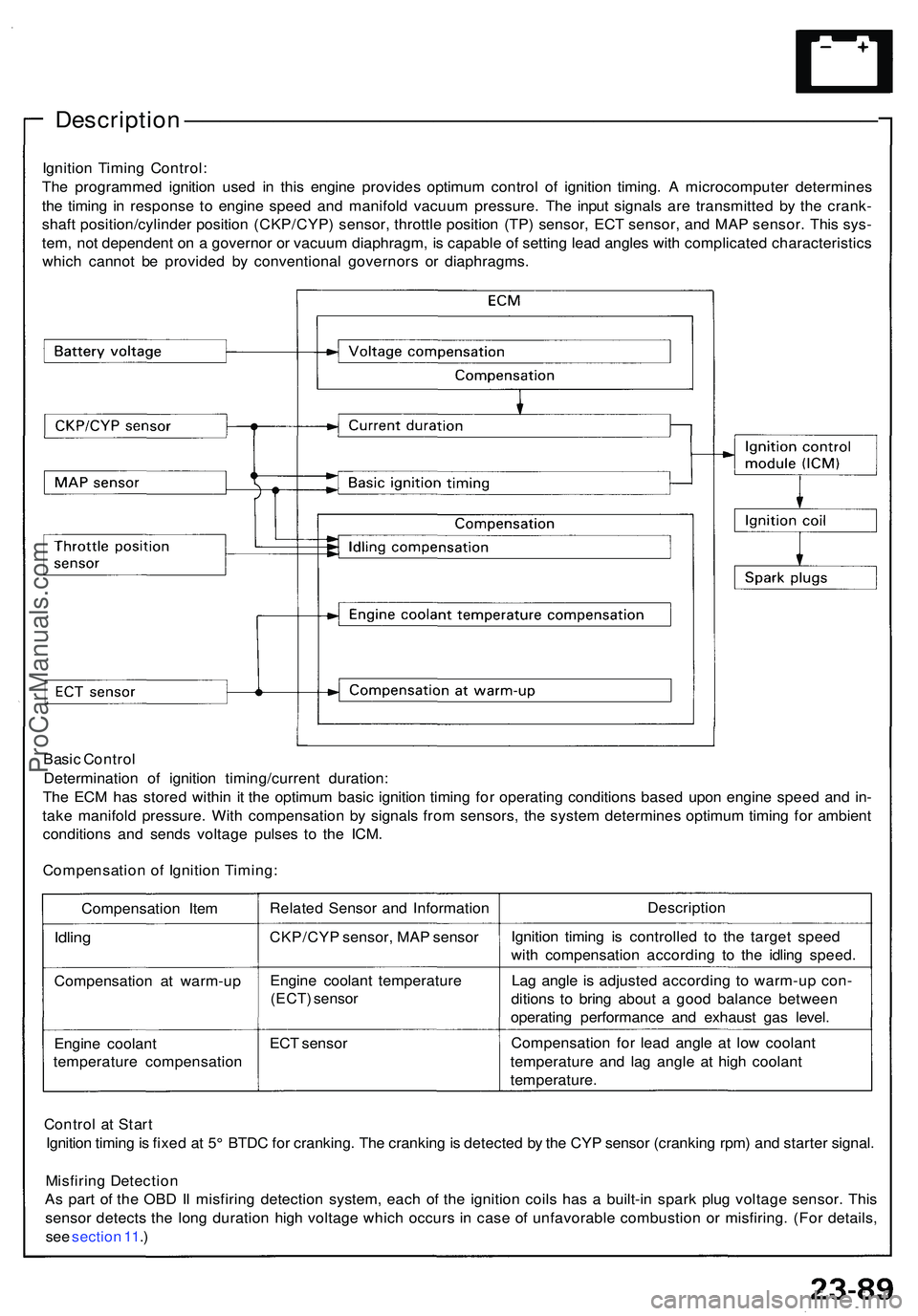
Ignition Timin g Control :
Th e programme d ignitio n use d i n thi s engin e provide s optimu m contro l o f ignitio n timing . A microcompute r determine s
th e timin g i n respons e t o engin e spee d an d manifol d vacuu m pressure . Th e inpu t signal s ar e transmitte d b y th e crank -
shaf t position/cylinde r positio n (CKP/CYP ) sensor , throttl e positio n (TP ) sensor , EC T sensor , an d MA P sensor . Thi s sys -
tem , no t dependen t o n a governo r o r vacuu m diaphragm , i s capabl e o f settin g lea d angle s wit h complicate d characteristic s
whic h canno t b e provide d b y conventiona l governor s o r diaphragms .
Basi c Contro l
Determinatio n of ignitio n timing/curren t duration :
Th e EC M ha s store d withi n i t th e optimu m basi c ignitio n timin g fo r operatin g condition s base d upo n engin e spee d an d in -
tak e manifol d pressure . Wit h compensatio n b y signal s fro m sensors , th e syste m determine s optimu m timin g fo r ambien t
condition s an d send s voltag e pulse s t o th e ICM .
Compensatio n o f Ignitio n Timing :
Compensatio n Ite m
Idlin g
Compensatio n a t warm-u p
Engin e coolan t
temperatur e compensatio nRelate
d Senso r an d Informatio n
CKP/CY P sensor , MA P senso r
Engin e coolan t temperatur e
(ECT) senso r
ECT senso r Descriptio
n
Ignitio n timin g i s controlle d t o th e targe t spee d
wit h compensatio n accordin g t o th e idlin g speed .
La g angl e i s adjuste d accordin g t o warm-u p con -
dition s t o brin g abou t a goo d balanc e betwee n
operatin g performanc e an d exhaus t ga s level .
Compensatio n fo r lea d angl e a t low coolan t
temperatur e an d la g angl e a t hig h coolan t
temperature .
Contro l a t Star t
Ignitio n timin g is fixe d a t 5 ° BTD C fo r cranking . Th e crankin g is detecte d b y th e CY P senso r (crankin g rpm ) an d starte r signal .
Misfirin g Detectio n
A s par t o f th e OB D II misfirin g detectio n system , eac h o f th e ignitio n coil s ha s a built-i n spar k plu g voltag e sensor . Thi s
senso r detect s th e lon g duratio n hig h voltag e whic h occur s i n cas e o f unfavorabl e combustio n o r misfiring . (Fo r details ,
se e sectio n 11 .)
ProCarManuals.com
Page 1266 of 1503
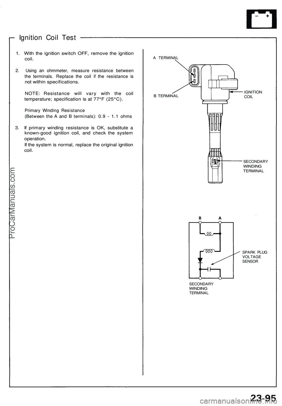
Ignition Coi l Tes t
1. Wit h th e ignitio n switc h OFF , remov e th e ignitio n
coil.
2. Usin g a n ohmmeter , measur e resistanc e betwee n
th e terminals . Replac e th e coi l i f th e resistanc e i s
no t withi n specifications .
NOTE: Resistanc e wil l var y wit h th e coi l
temperature ; specificatio n i s a t 77° F (25°C) .
Primary Windin g Resistanc e
(Betwee n th e A an d B terminals) : 0.9 - 1. 1 ohm s
3. I f primar y windin g resistanc e i s OK , substitut e aknown-goo d ignitio n coil , an d chec k th e syste m
operation .
If th e syste m is normal , replac e th e origina l ignitio n
coil.
A TERMINA L
B TERMINA LIGNITIONCOIL
SECONDAR Y
WINDINGTERMINA L
SPARK PLU G
VOLTAG E
SENSO R
SECONDAR Y
WINDINGTERMINA L
ProCarManuals.com
Page 1284 of 1503
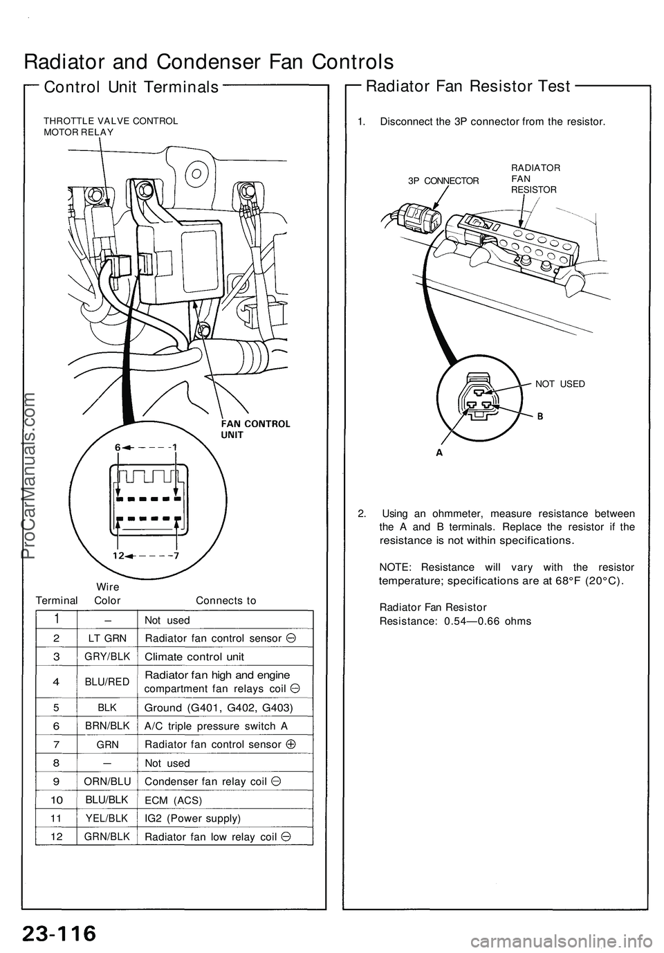
Radiator and Condenser Fan Controls
Control Unit Terminals
THROTTLE VALVE CONTROL
MOTOR RELAY
Wire
Terminal Color
Connects to
1
2
3
4
5
6
7
8
9
10
11
12
-
LT GRN
GRY/BLK
BLU/RED
BLK
BRN/BLK
GRN
—
ORN/BLU
BLU/BLK
YEL/BLK
GRN/BLK
Not used
Radiator fan control sensor
Climate control unit
Radiator fan high and engine
compartment fan relays coil
Ground (G401, G402, G403)
A/C triple pressure switch A
Radiator fan control sensor
Not used
Condenser fan relay coil
ECM
(ACS)
IG2 (Power supply)
Radiator fan low relay coil
1. Disconnect the 3P connector from the resistor.
3P CONNECTOR
RADIATOR
FAN
RESISTOR
NOT USED
2. Using an ohmmeter, measure resistance between
the A and B terminals. Replace the resistor if the
resistance is not within specifications.
NOTE: Resistance will vary with the resistor
temperature; specifications are at 68°F (20°C).
Radiator Fan Resistor
Resistance: 0.54—0.66 ohms
Radiator Fan Resistor TestProCarManuals.com