ACURA RL KA9 1996 Service Repair Manual
Manufacturer: ACURA, Model Year: 1996, Model line: RL KA9, Model: ACURA RL KA9 1996Pages: 1954, PDF Size: 61.44 MB
Page 1171 of 1954
Troubleshooting
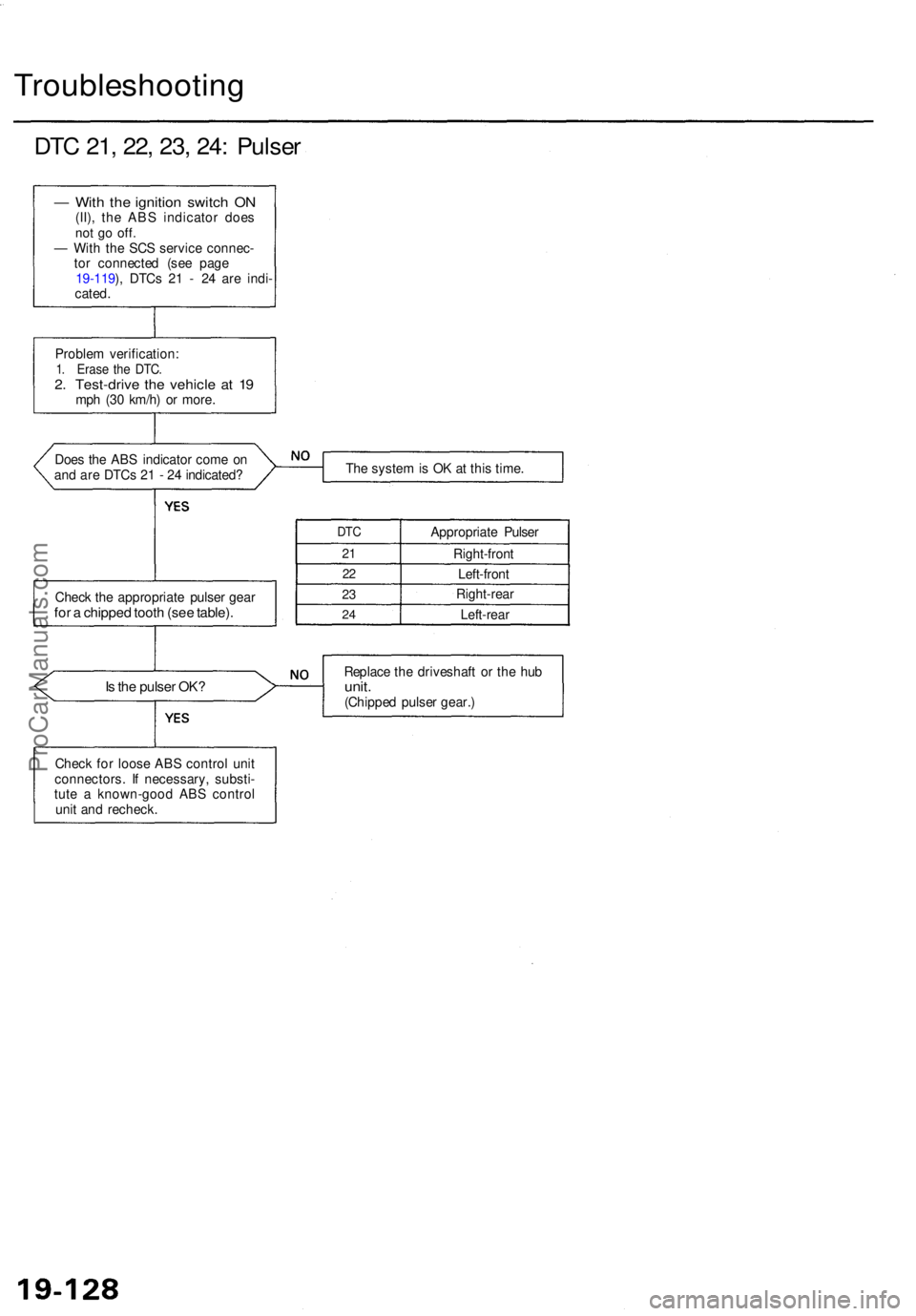
DTC 21 , 22 , 23 , 24 : Pulse r
— Wit h th e ignitio n switc h O N(II) , th e AB S indicato r doe snot g o off .— Wit h th e SC S servic e connec -
to r connecte d (se e pag e
19-119 ), DTC s 2 1 - 2 4 ar e indi -
cated .
Proble m verification :
1. Eras e th e DTC .2. Test-driv e th e vehicl e a t 1 9mp h (3 0 km/h ) o r more .
Doe s th e AB S indicato r com e o n
an d ar e DTC s 2 1 - 2 4 indicated ?
Chec k th e appropriat e pulse r gea r
for a chippe d toot h (se e table) .
The syste m is O K a t thi s time .
DTC
21
22
23
2 4
Appropriat e Pulse r
Right-fron t
Left-fron t
Right-rea r
Left-rea r
Is th e pulse r OK ?Replac e th e driveshaf t o r th e hu bunit .(Chippe d pulse r gear. )
Chec k fo r loos e AB S contro l uni t
connectors . I f necessary , substi -
tut e a known-goo d AB S contro l
uni t an d recheck .
ProCarManuals.com
Page 1172 of 1954
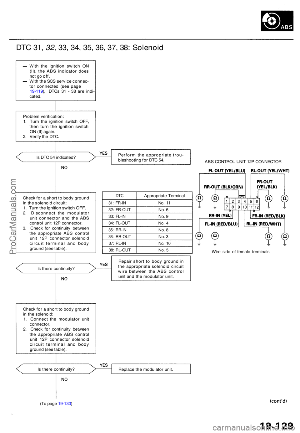
DTC 31 , 32, 33, 34 , 35 , 36 , 37 , 38 : Solenoi d
With th e ignitio n switc h O N
(II) , th e AB S indicato r doe s
not g o off .With th e SC S servic e connec -
to r connecte d (se e pag e
19-119 ), DTC s 3 1 - 3 8 ar e indi -
cated .
Proble m verification :
1 . Tur n th e ignitio n switc h OFF ,
then tur n th e ignitio n switc hON (II ) again .
2 . Verif y th e DTC .
I s DT C 5 4 indicated ?
Chec k fo r a shor t t o bod y groun d
i n th e solenoid :
1 . Connec t th e modulato r uni t
connector .2. Chec k fo r continuit y betwee n
th e appropriat e AB S contro l
uni t 12 P connecto r solenoi d
circuit termina l an d bod ygroun d (se e table) .
I s ther e continuity ?
(T o pag e 19-130 ) Perfor
m th e appropriat e trou -
bleshootin g fo r DT C 54 .
ABS CONTRO L UNI T 12 P CONNECTO R
DTC
31: FR-I N
32: FR-OU T
33: FL-I N
34: FL-OU T
35: RR-I N
36: RR-OU T
37: RL-I N
38: RL-OU T
Appropriat e Termina l
No. 1 1
No . 6
No . 9
No . 4
No . 8
No . 3
No . 1 0
No . 5Wir e sid e o f femal e terminal s
Repai r shor t t o bod y groun d in
th e appropriat e solenoi d circui t
wir e betwee n th e ABS contro l
uni t an d th e modulato r unit .
Replac e th e modulato r unit .
Chec
k fo r a shor t t o bod y groun d
i n th e solenoi d circuit :
1. Tur n th e ignitio n switc h OFF .2. Disconnec t th e modulato r
uni t connecto r an d th e AB S
contro l uni t 12 P connector .
3 . Chec k fo r continuit y betwee n
th e appropriat e AB S contro l
uni t 12 P connecto r solenoi d
circuit termina l an d bod ygroun d (se e table) .
I s ther e continuity ?
ProCarManuals.com
Page 1173 of 1954
Troubleshooting
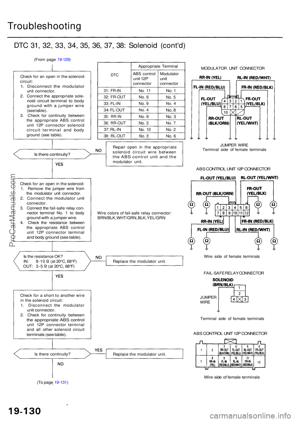
DTC 31 , 32, 33, 34, 35, 36 , 37 , 38 : Solenoi d (cont'd )
(From pag e 19-129 )
Chec k fo r an ope n in th e solenoi d
circuit :
1. Disconnec t th e modulato runit connector .
2 . Connec t th e appropriat e sole -
noid circui t termina l t o bod ygroun d wit h a jumpe r wir e(see table) .
3 . Chec k fo r continuit y betwee n
th e appropriat e AB S contro l
uni t 12 P connecto r solenoi d
circuit termina l an d bod ygroun d (se e table) .
Is ther e continuity ?
Is th e resistanc e OK ?IN: 8-1 0 (a t 20°C , 68°F )OUT: 3- 5 (a t 20°C , 68°F )
Chec k fo r a shor t t o anothe r wir e
i n th e solenoi d circuit :
1 . Disconnec t th e modulato r
unit connector .2. Chec k fo r continuit y betwee nthe appropriat e AB S contro lunit 12 P connecto r termina l
an d al l othe r solenoi d circui t
terminal s (se e table) .
Is ther e continuity ?
(T o pag e 19-131 )
DTC
31: FR-I N
32: FR-OU T
33: FL-I N
34 : FL-OU T
35: RR-I N
36: RR-OU T
37: RL-I N
38: RL-OU T
Appropriat e Termina l
AB S contro l
unit 12 Pconnecto r
No. 1 1
No . 6
No . 9
No . 4
No . 8
No . 3
No . 1 0
No. 5
Modulato runitconnecto r
No. 1
No . 5
No . 4
No . 8
No . 3
No . 7
No . 2
No . 6
Repai r ope n i n th e appropriat e
solenoi d circui t wir e betwee n
the AB S contro l uni t an d th emodulato r unit . JUMPE
R WIR E
Termina l sid e o f femal e terminal s
ABS CONTRO L UNI T 12 P CONNECTO R
Wire color s o f fail-saf e rela y connector :
BRN/BLK , WHT/GRN , BLK , YEL/GR N
Replac e th e modulato r unit . Wir
e sid e o f femal e terminal s
FAIL-SAF E RELA Y CONNECTO R
JUMPE R
WIRE
Termina l sid e o f femal e terminal s
ABS CONTRO L UNI T 12 P CONNECTO R
Replace th e modulato r unit .
Wire sid e o f femal e terminal s
Check fo r a n ope n in th e solenoid :
1 . Remov e th e jumpe r wir e fro m
th e modulato r uni t connector .
2. Connec t th e modulato r uni tconnector .
3 . Connec t th e fail-saf e rela y con -
necto r termina l No . 1 to bod y
groun d wit h a jumpe r wire .4. Chec k th e resistanc e betwee n
th e appropriat e AB S contro l
uni t 12 P connecto r termina l
and bod y groun d (se e table) .
MODULATO R UNI T CONNECTO R
ProCarManuals.com
Page 1174 of 1954
(From pag e 19-130 )
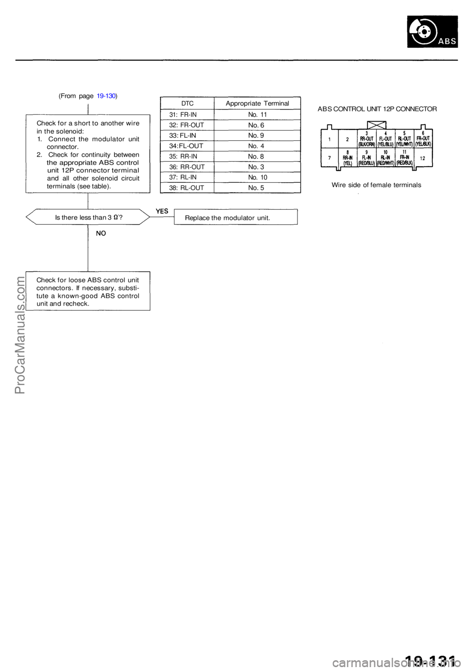
Chec k fo r a shor t t o anothe r wir e
i n th e solenoid :
1 . Connec t th e modulato r uni t
connector .
2 . Chec k fo r continuit y betwee n
the appropriat e AB S contro lunit 12 P connecto r termina land al l othe r solenoi d circui t
terminal s (se e table) .
DTC
31: FR-I N
32: FR-OU T
33: FL-I N
34 : FL-OU T
35: RR-I N
36: RR-OU T
37: RL-I N
38: RL-OU T
Appropriat e Termina l
No. 1 1
No . 6
No . 9
No . 4
No . 8
No . 3
No . 1 0
No . 5
Is ther e les s tha n 3 ? AB
S CONTRO L UNI T 12 P CONNECTO R
Wir e sid e o f femal e terminal s
Replac e th e modulato r unit .
Chec k fo r loos e AB S contro l uni t
connectors . I f necessary , substi -
tut e a known-goo d AB S contro l
uni t an d recheck .
ProCarManuals.com
Page 1175 of 1954
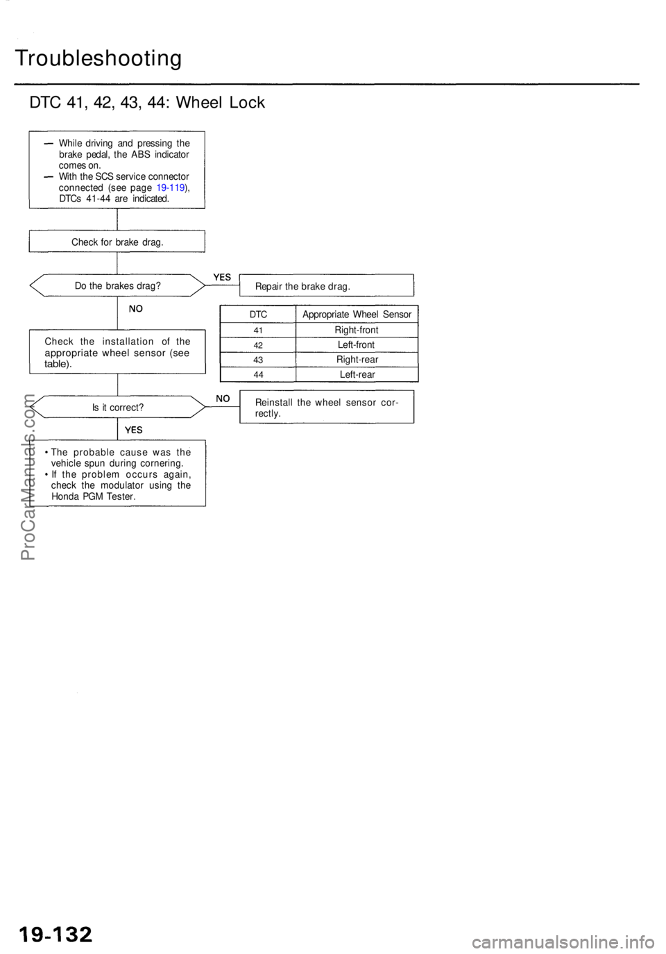
Troubleshooting
DTC 41 , 42 , 43 , 44 : Whee l Loc k
Do th e brake s drag ?
Repair th e brak e drag .
Chec k th e installatio n o f th e
appropriat e whee l senso r (se etable) .
DTC
41
4 2
43
4 4
Appropriat e Whee l Senso r
Right-fron t
Left-fron t
Right-rea r
Left-rear
I s i t correct ? Reinstal
l th e whee l senso r cor -
rectly .
Th e probabl e caus e wa s th e
vehicl e spu n durin g cornering .
I f th e proble m occur s again ,
chec k th e modulato r usin g th e
Hond a PG M Tester .
Whil
e drivin g an d pressin g th e
brak e pedal , th e AB S indicato r
come s on .
Wit h th e SC S servic e connecto r
connecte d (se e pag e 19-119 ),
DTC s 41-4 4 ar e indicated .
Chec k fo r brak e drag .
ProCarManuals.com
Page 1176 of 1954
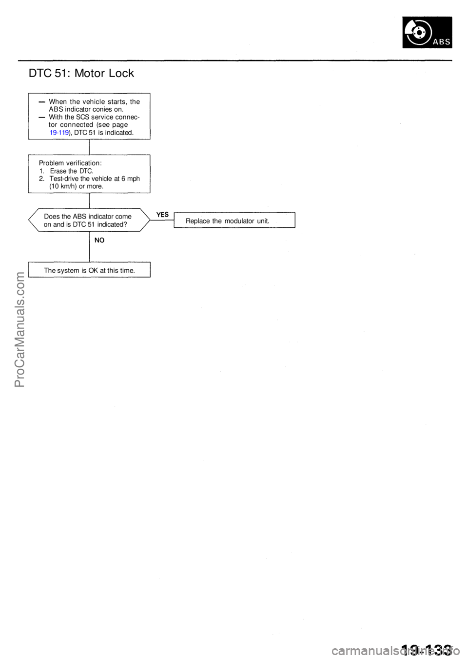
DTC 51 : Moto r Loc k
Whe n th e vehicl e starts , th e
AB S indicato r conie s on .
Wit h th e SC S servic e connec -
to r connecte d (se e pag e
19-119 ), DT C 5 1 is indicated .
Proble m verification :
1. Eras e th e DTC .2. Test-driv e th e vehicl e a t 6 mp h
(1 0 km/h ) o r more .
Doe s th e AB S indicato r com e
o n an d is DT C 5 1 indicated ? Replac
e th e modulato r unit .
Th e syste m is O K a t thi s time .
ProCarManuals.com
Page 1177 of 1954
Troubleshooting
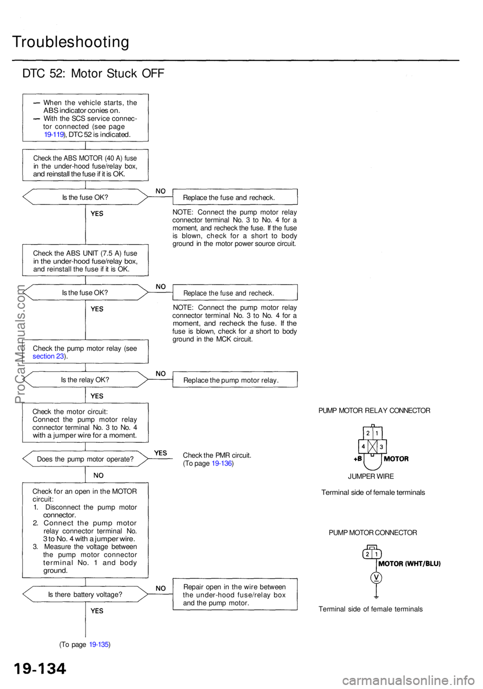
DTC 52 : Moto r Stuc k OF F
Whe n th e vehicl e starts , th eAB S indicato r conie s on .Wit h th e SC S servic e connec -
to r connecte d (se e pag e
19-119 ), DT C 52 is indicated .
Check th e AB S MOTO R (4 0 A ) fus ein th e under-hoo d fuse/rela y box ,and reinstal l th e fus e if i t i s OK .
Is th e fus e OK ?
Chec k th e AB S UNI T (7. 5 A ) fus e
in th e under-hoo d fuse/rela y box ,and reinstal l th e fus e if i t i s OK .
I s th e fus e OK ?
Chec k th e pum p moto r rela y (se e
sectio n 23 ).
I s th e rela y OK ?
Chec k th e moto r circuit :
Connec t th e pum p moto r rela y
connecto r termina l No . 3 to No . 4
wit h a jumpe r wir e fo r a moment .
Does th e pum p moto r operate ?
Chec k fo r a n ope n in th e MOTO R
circuit :
1 . Disconnec t th e pum p moto r
connector .2. Connec t th e pum p moto rrelay connecto r termina l No .3 to No . 4 wit h a jumpe r wire .3. Measur e th e voltag e betwee n
th e pum p moto r connecto r
terminal No . 1 an d bod yground .
Is ther e batter y voltage ?
(T o pag e 19-135 ) Replac
e th e fus e an d recheck .
NOTE : Connec t th e pum p moto r rela y
connecto r termina l No . 3 to No . 4 fo r a
moment , an d rechec k th e fuse . I f th e fus e
i s blown , chec k fo r a shor t t o bod y
groun d i n th e moto r powe r sourc e circuit .
Replac e th e fus e an d recheck .
NOTE: Connec t th e pum p moto r rela y
connecto r termina l No . 3 to No . 4 fo r a
moment , an d rechec k th e fuse . I f th efus e i s blown , chec k fo r a shor t t o bod y
groun d i n th e MC K circuit .
Replac e th e pum p moto r relay .
PUMP MOTO R RELA Y CONNECTO R
Chec k th e PM R circuit .
(T o pag e 19-136 )
Repai r ope n in th e wir e betwee n
th e under-hoo d fuse/rela y bo x
an d th e pum p motor .
Terminal sid e o f femal e terminal s
PUM
P MOTO R CONNECTO R
JUMPE
R WIR E
Termina l sid e o f femal e terminal s
ProCarManuals.com
Page 1178 of 1954
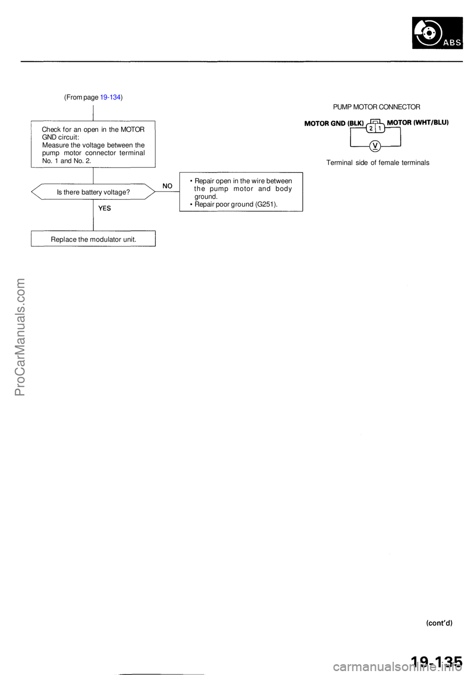
(From pag e 19-134 )
Chec k fo r a n ope n in th e MOTO R
GN D circuit :
Measur e th e voltag e betwee n th e
pum p moto r connecto r termina l
No. 1 an d No . 2 .
Is ther e batter y voltage ? PUM
P MOTO R CONNECTO R
Termina l sid e o f femal e terminal s
Repai r ope n in th e wir e betwee n
th e pum p moto r an d bod yground .Repair poo r groun d (G251) .
Replac e th e modulato r unit .
ProCarManuals.com
Page 1179 of 1954
Troubleshooting
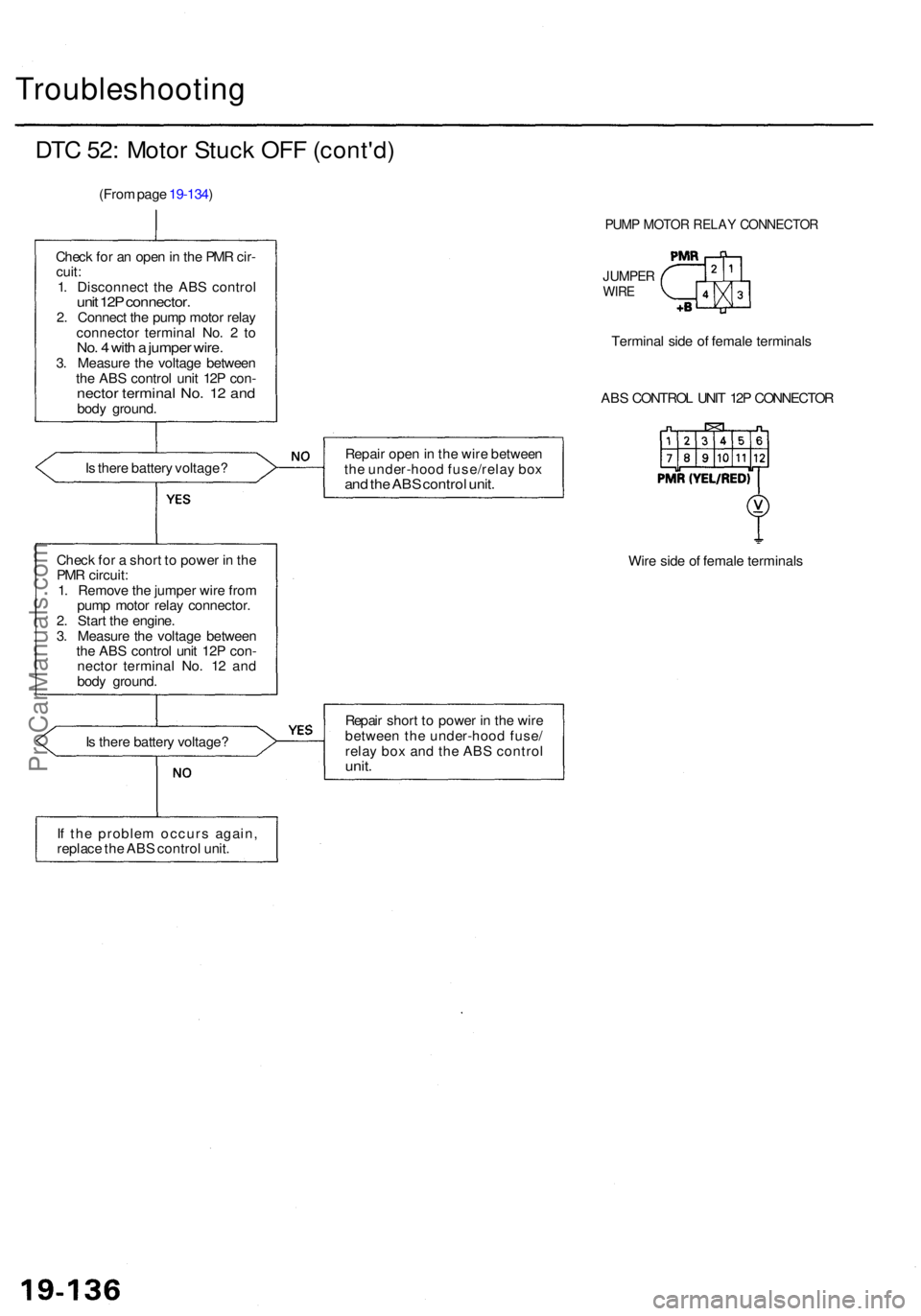
DTC 52 : Moto r Stuc k OF F (cont'd )
(From pag e 19-134 )
Chec k fo r a n ope n in th e PM R cir -
cuit :
1 . Disconnec t th e AB S contro l
unit 12 P connector .2. Connec t th e pum p moto r rela y
connecto r termina l No . 2 to
No . 4 wit h a jumpe r wire .3. Measur e th e voltag e betwee n
th e AB S contro l uni t 12 P con -
necto r termina l No . 1 2 an dbod y ground .
I s ther e batter y voltage ?
Chec k fo r a shor t t o powe r i n th e
PM R circuit :
1 . Remov e th e jumpe r wir e fro m
pum p moto r rela y connector .
2 . Star t th e engine .
3 . Measur e th e voltag e betwee n
th e AB S contro l uni t 12 P con -
necto r termina l No . 1 2 an d
bod y ground . Repai
r ope n in th e wir e betwee n
th e under-hoo d fuse/rela y bo x
and th e AB S contro l unit .
Wire sid e o f femal e terminal s
I s ther e batter y voltage ? Repai
r shor t t o powe r i n th e wir e
betwee n th e under-hoo d fuse /
rela y bo x an d th e AB S contro l
unit.
If th e proble m occur s again ,
replac e th e AB S contro l unit .
PUM P MOTO R RELA Y CONNECTO R
JUMPERWIRE
Termina l sid e o f femal e terminal s
AB S CONTRO L UNI T 12 P CONNECTO R
ProCarManuals.com
Page 1180 of 1954
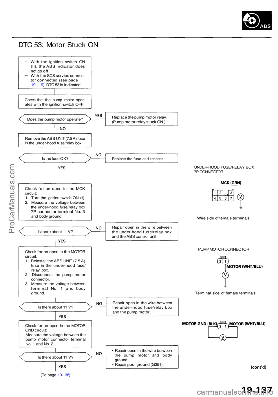
DTC 53 : Moto r Stuc k O N
Wit h th e ignitio n switc h O N
(II) , th e AB S indicato r doe s
not g o off .Wit h th e SC S servic e connec -
to r connecte d (se e pag e
19-119 ), DT C 53 is indicated .
Chec k tha t th e pum p moto r oper -
ate s wit h th e ignitio n switc h OFF .
Doe s th e pum p moto r operate ?
Remov e th e AB S UNI T (7. 5 A ) fus e
i n th e under-hoo d fuse/rela y box .
I s th e fus e OK ?
Chec k fo r a n ope n i n th e MC K
circuit :1. Tur n th e ignitio n switc h O N (II) .
2 . Measur e th e voltag e betwee n
th e under-hoo d fuse/rela y bo x
7P connecto r termina l No . 3an d bod y ground .
I s ther e abou t 1 1 V ?
Chec k fo r a n ope n in th e MOTO R
circuit:1. Reinstal l th e AB S UNI T (7. 5 A )
fus e i n th e under-hoo d fuse /
rela y box .
2 . Disconnec t th e pum p moto r
connector .3. Measur e th e voltag e betwee n
termina l No . 1 an d bod y
ground .
I s ther e abou t 1 1 V ?
Chec k fo r a n ope n in th e MOTO R
GN D circuit :
Measur e th e voltag e betwee n th e
pum p moto r connecto r termina l
No. 1 an d No . 2 .
Is ther e abou t 1 1 V ?
(To pag e 19-138 )
Replac e th e pum p moto r relay .
(Pum p moto r rela y stuc k ON. )
Replac e th e fus e an d recheck .
UNDER-HOO D FUSE/RELA Y BO X7P CONNECTO R
Wire sid e o f femal e terminal s
Repai r ope n in th e wir e betwee n
th e under-hoo d fuse/rela y bo x
an d th e AB S contro l unit .
PUMP MOTO R CONNECTO R
Termina l sid e o f femal e terminal s
Repai r ope n in th e wir e betwee n
th e under-hoo d fuse/rela y bo x
an d th e pum p motor .
Repai r ope n in th e wir e betwee n
th e pum p moto r an d bod y
ground .Repair poo r groun d (G251) .
ProCarManuals.com