fuse box ACURA RL KA9 1996 Service Repair Manual
[x] Cancel search | Manufacturer: ACURA, Model Year: 1996, Model line: RL KA9, Model: ACURA RL KA9 1996Pages: 1954, PDF Size: 61.44 MB
Page 1764 of 1954
Troubleshooting
'00 - 0 1 Model s
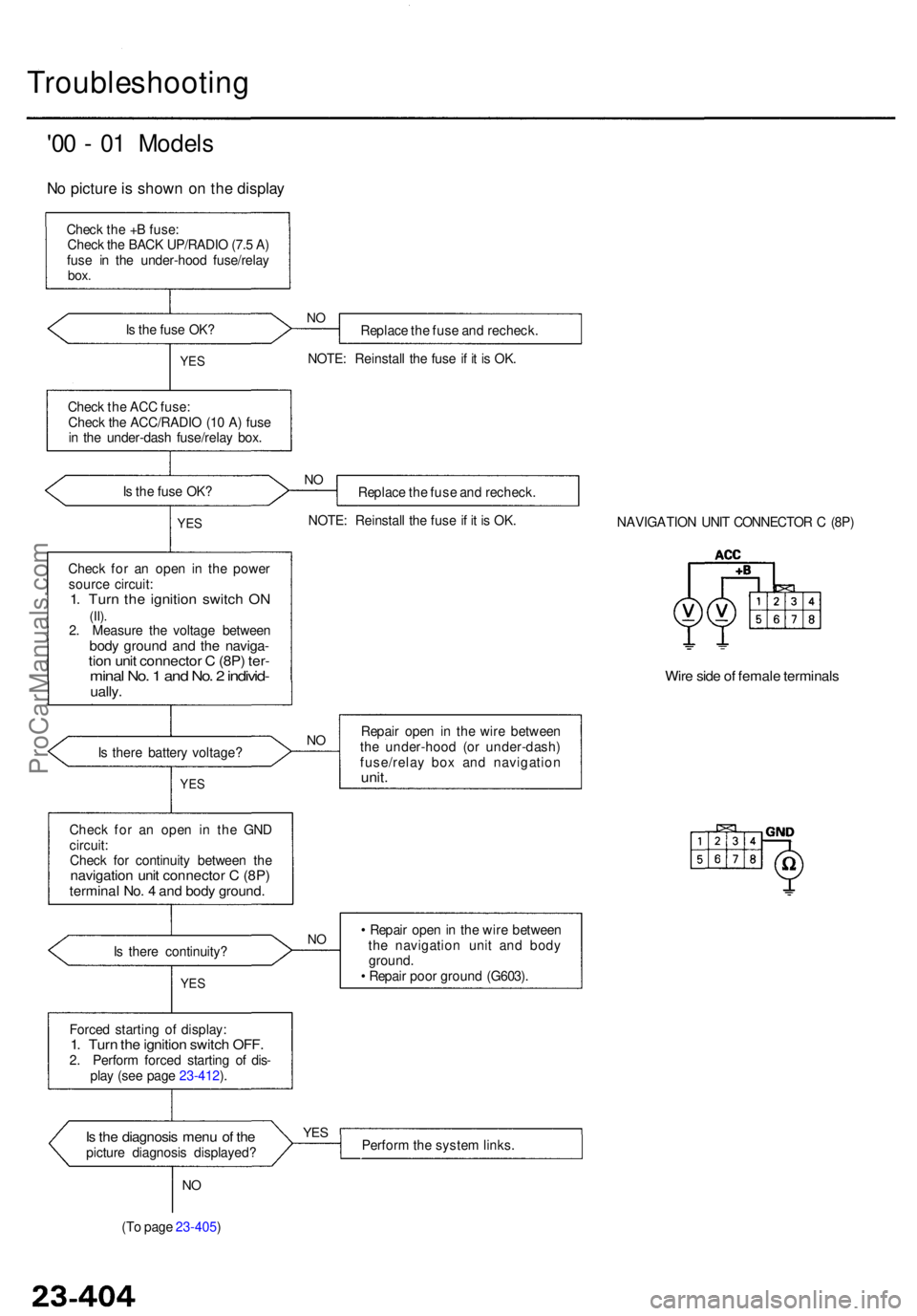
No pictur e is show n o n th e displa y
Check th e + B fuse :
Chec k th e BAC K UP/RADI O (7. 5 A )
fus e i n th e under-hoo d fuse/rela y
box.
Is th e fus e OK ?
Replace th e fus e an d recheck .
NOTE : Reinstal l th e fus e if i t i s OK .NO
YE S
Chec k th e AC C fuse :
Chec k th e ACC/RADI O (1 0 A ) fus e
i n th e under-das h fuse/rela y box .
I s th e fus e OK ?
NOReplac e th e fus e an d recheck .
NOTE : Reinstal l th e fus e if i t i s OK .
YES
Chec k fo r a n ope n i n th e powe r
sourc e circuit :
1. Tur n th e ignitio n switc h O N(II).2. Measur e th e voltag e betwee nbody groun d an d th e naviga -tion uni t connecto r C (8P ) ter -mina l No . 1 an d No . 2 individ -ually.
NAVIGATIO N UNI T CONNECTO R C (8P )
Wire sid e o f femal e terminal s
Is ther e batter y voltage ?NORepai r ope n i n th e wir e betwee n
th e under-hoo d (o r under-dash )
fuse/rela y bo x an d navigatio n
unit.YES
Chec k fo r a n ope n i n th e GN D
circuit :
Chec k fo r continuit y betwee n th e
navigatio n uni t connecto r C (8P )termina l No . 4 an d bod y ground .
Is ther e continuity ?
YES
NO• Repai r ope n in th e wir e betwee n
th e navigatio n uni t an d bod y
ground .
• Repai r poo r groun d (G603) .
Force d startin g o f display :
1. Tur n th e ignitio n switc h OFF .2. Perfor m force d startin g o f dis -
pla y (se e pag e 23-412 ).
Is th e diagnosi s men u o f th epictur e diagnosi s displayed ?
YESPerfor m th e syste m links .
NO
(T o pag e 23-405 )
ProCarManuals.com
Page 1797 of 1954
2. To reinstall the connector, push it into position until
it clicks, then close its lid.
Precautions/Procedures
Inspection After Deployment
After a collision in which the airbags were deployed,
replace the deployed parts (airbag, seat belt tensioner
and side airbag), the SRS unit, the side impact sensor on
the side which deployed, and any related parts, and
inspect the following:
1. Inspect all the SRS wire harnesses. Replace, don't
repair, any damaged harnesses.
2. Inspect the cable reel for heat damage. If there is any
damage, replace the cable reel.
3. After the vehicle is completely repaired, turn the igni-
tion switch on. If the SRS indicator light comes on
for about 6 seconds and then goes off, the SRS sys-
tem is OK. If the indicator light does not function
properly, go to SRS Troubleshooting.
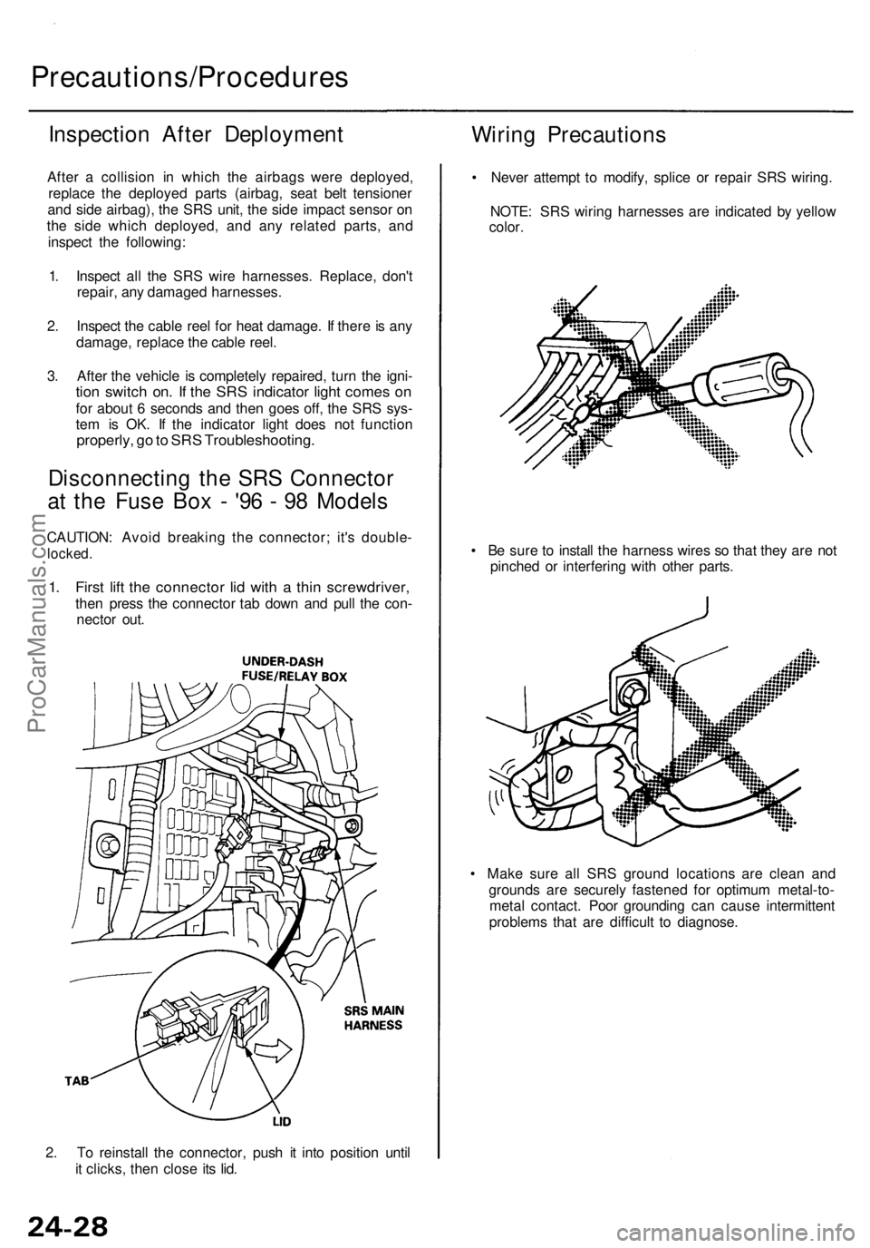
Disconnecting the SRS Connector
at the Fuse Box - '96 - 98 Models
CAUTION: Avoid breaking the connector; it's double-
locked.
1. First lift the connector lid with a thin screwdriver,
then press the connector tab down and pull the con-
nector out.
Wiring Precautions
• Never attempt to modify, splice or repair SRS wiring.
NOTE: SRS wiring harnesses are indicated by yellow
color.
• Be sure to install the harness wires so that they are not
pinched or interfering with other parts.
• Make sure all SRS ground locations are clean and
grounds are securely fastened for optimum metal-to-
metal contact. Poor grounding can cause intermittent
problems that are difficult to diagnose.ProCarManuals.com
Page 1809 of 1954
24-181
24-181
24-181
24-181
24-76
24-81
24-18 1
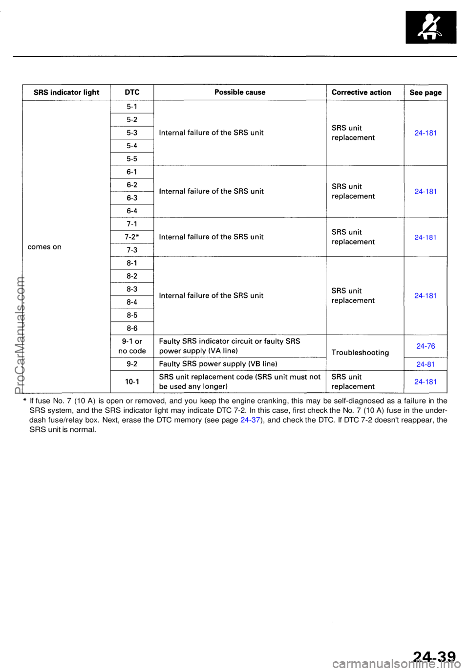
If fus e No . 7 (1 0 A ) i s ope n o r removed , an d yo u kee p th e engin e cranking , thi s ma y b e self-diagnose d a s a failur e in th e
SR S system , an d th e SR S indicato r ligh t ma y indicat e DT C 7-2 . I n thi s case , firs t chec k th e No . 7 (1 0 A ) fus e in th e under -
das h fuse/rela y box . Next , eras e th e DT C memor y (se e pag e 24-37 ), an d chec k th e DTC . I f DT C 7- 2 doesn' t reappear , th e
SR S uni t i s normal .
ProCarManuals.com
Page 1810 of 1954
To UNDER-DASH
FUSE/RELAY BOX
2P CONNECTOR
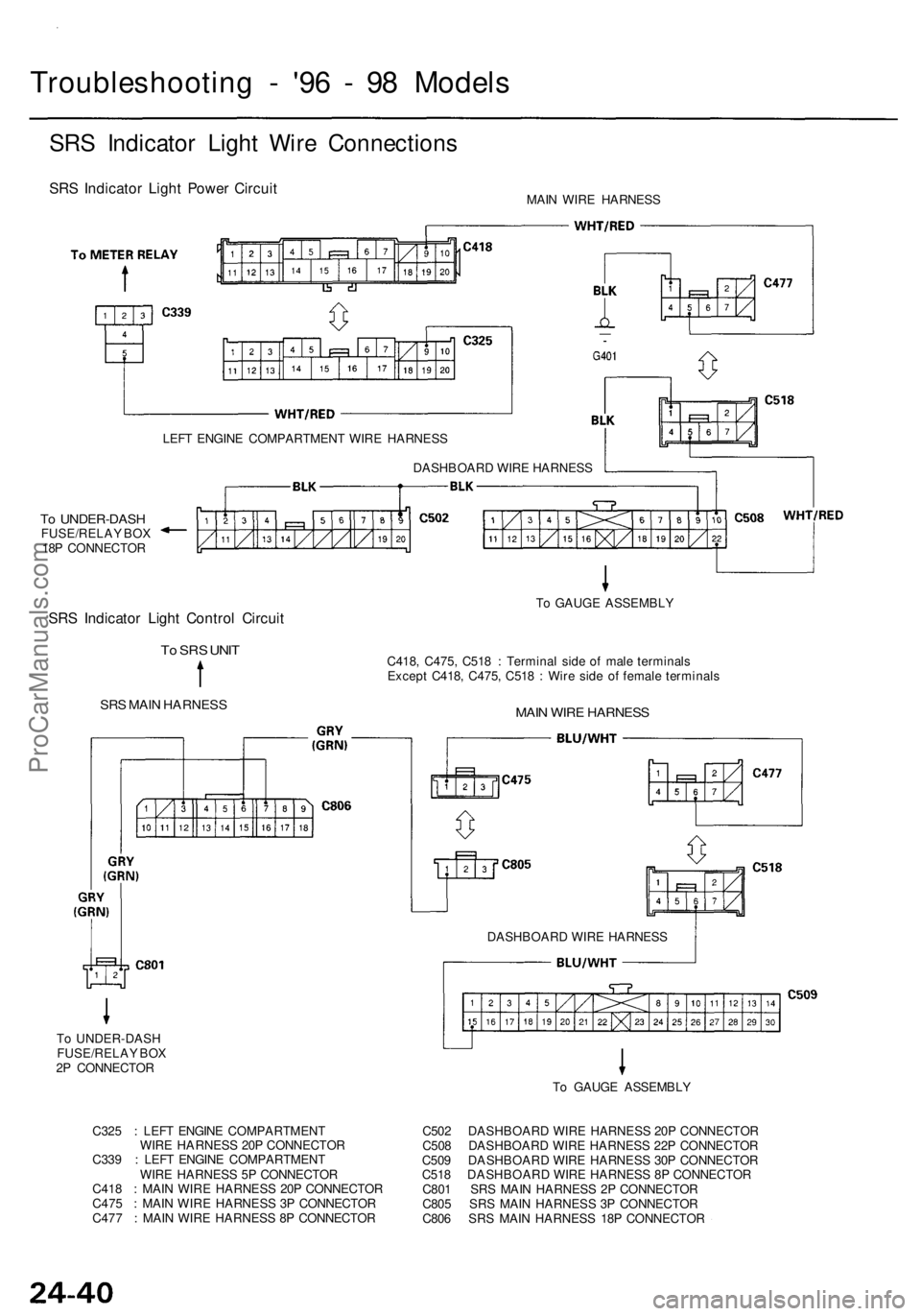
Troubleshooting - '96 - 98 Models
SRS Indicator Light Wire Connections
SRS Indicator Light Power Circuit
MAIN WIRE HARNESS
LEFT ENGINE COMPARTMENT WIRE HARNESS
To UNDER-DASH
FUSE/RELAY BOX
18P CONNECTOR
SRS Indicator Light Control Circuit
To SRS UNIT
SRS MAIN HARNESS
C418, C475, C518 : Terminal side of male terminals
Except C418, C475, C518 : Wire side of female terminals
MAIN WIRE HARNESS
To GAUGE ASSEMBLY
DASHBOARD WIRE HARNESS
DASHBOARD WIRE HARNESS
To GAUGE ASSEMBLY
C325 : LEFT ENGINE COMPARTMENT
WIRE HARNESS 20P CONNECTOR
C339 : LEFT ENGINE COMPARTMENT
WIRE HARNESS 5P CONNECTOR
C418 : MAIN WIRE HARNESS 20P CONNECTOR
C475 : MAIN WIRE HARNESS 3P CONNECTOR
C477 : MAIN WIRE HARNESS 8P CONNECTOR
C502 DASHBOARD WIRE HARNESS 20P CONNECTOR
C508 DASHBOARD WIRE HARNESS 22P CONNECTOR
C509 DASHBOARD WIRE HARNESS 30P CONNECTOR
C518 DASHBOARD WIRE HARNESS 8P CONNECTOR
C801 SRS MAIN HARNESS 2P CONNECTOR
C805 SRS MAIN HARNESS 3P CONNECTOR
C806 SRS MAIN HARNESS 18P CONNECTORProCarManuals.com
Page 1811 of 1954
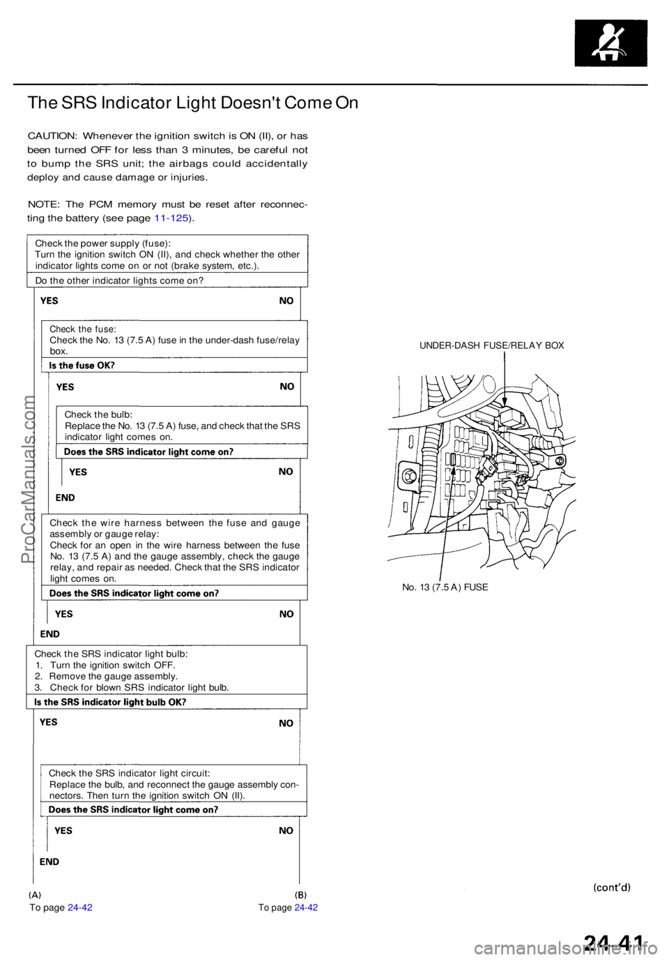
To page 24-42 To page 24-42
The SR S Indicato r Ligh t Doesn' t Com e O n
CAUTION : Wheneve r th e ignitio n switc h is O N (II) , o r ha s
bee n turne d OF F fo r les s tha n 3 minutes , b e carefu l no t
to bum p th e SR S unit ; th e airbag s coul d accidentall y
deploy an d caus e damag e o r injuries .
NOTE: Th e PC M memor y mus t b e rese t afte r reconnec -
ting th e batter y (se e pag e 11-125 ).
Chec k th e powe r suppl y (fuse) :
Tur n th e ignitio n switc h O N (II) , an d chec k whethe r th e othe r
indicato r light s com e o n o r no t (brak e system , etc.) .
D o th e othe r indicato r light s com e on ?
Chec k th e fuse :Chec k th e No . 1 3 (7. 5 A ) fus e in th e under-das h fuse/rela ybox.
Chec k th e bulb :
Replac e th e No . 1 3 (7. 5 A ) fuse , an d chec k tha t th e SR S
indicato r ligh t come s on .
Chec k th e wir e harnes s betwee n th e fus e an d gaug e
assembl y o r gaug e relay :
Chec k fo r a n ope n i n th e wir e harnes s betwee n th e fus e
No . 1 3 (7. 5 A ) an d th e gaug e assembly , chec k th e gaug e
relay , an d repai r a s needed . Chec k tha t th e SR S indicato r
ligh t come s on .
Chec k th e SR S indicato r ligh t bulb :
1 . Tur n th e ignitio n switc h OFF .
2 . Remov e th e gaug e assembly .
3 . Chec k fo r blow n SR S indicato r ligh t bulb .
Chec k th e SR S indicato r ligh t circuit :
Replac e th e bulb , an d reconnec t th e gaug e assembl y con -
nectors . The n tur n th e ignitio n switc h O N (II) .
UNDER-DAS H FUSE/RELA Y BO X
No. 1 3 (7. 5 A ) FUS E
ProCarManuals.com
Page 1863 of 1954
Troubleshooting - '9 9 - 0 1 Model s
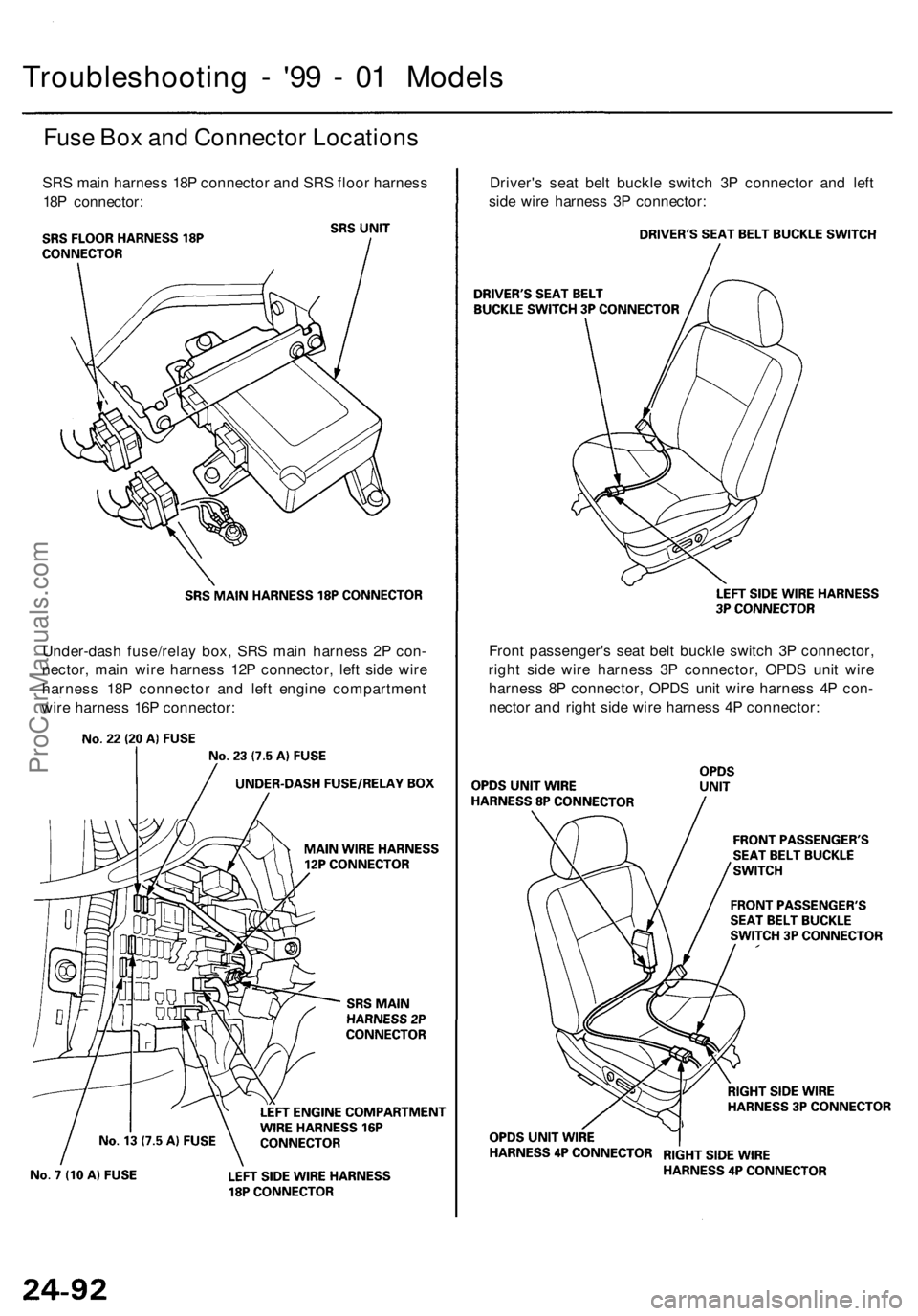
Fuse Bo x an d Connecto r Location s
SRS mai n harnes s 18 P connecto r an d SR S floo r harnes s
18 P connector : Driver'
s sea t bel t buckl e switc h 3 P connecto r an d lef t
sid e wir e harnes s 3 P connector :
Fron t passenger' s sea t bel t buckl e switc h 3 P connector ,
righ t sid e wir e harnes s 3 P connector , OPD S uni t wir e
harnes s 8 P connector , OPD S uni t wir e harnes s 4 P con -
necto r an d righ t sid e wir e harnes s 4 P connector :
Under-das
h fuse/rela y box , SR S mai n harnes s 2 P con -
nector , mai n wir e harnes s 12 P connector , lef t sid e wir e
harnes s 18 P connecto r an d lef t engin e compartmen t
wir e harnes s 16 P connector :
ProCarManuals.com
Page 1920 of 1954
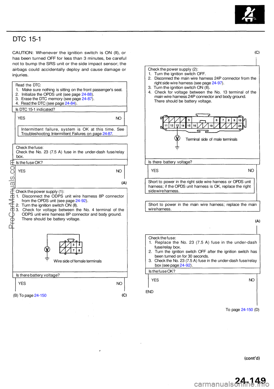
DTC 15- 1
CAUTION : Wheneve r th e ignitio n switc h is O N (II) , o r
ha s bee n turne d OF F fo r les s tha n 3 minutes , b e carefu l
not t o bum p th e SR S uni t o r th e sid e impac t sensor ; th e
airbag s coul d accidentall y deplo y an d caus e damag e o r
injuries .
Read th e DTC :1. Mak e sur e nothin g is sittin g o n th e fron t passenger' s seat .
2 . Initializ e th e OPD S uni t (se e pag e 24-88 ).
3 . Eras e th e DT C memor y (se e pag e 24-87 ).
4 . Rea d th e DT C (se e pag e 24-84 ).
I s DT C 15- 1 indicated ?
YESNO
Intermitten t failure , syste m is O K a t thi s time . Se e
Troubleshootin g Intermitten t Failure s o n pag e 24-87 .
Chec k th e fuse :
Chec k th e No . 2 3 (7. 5 A ) fus e i n th e under-das h fuse/rela y
box.
Is th e fus e OK ?
YESNO
Chec k th e powe r suppl y (1) :
1 . Disconnec t th e ODP S uni t wir e harnes s 8 P connecto r
fro m th e OPD S uni t (se e pag e 24-92 ).
2 . Tur n th e ignitio n switc h O N (II) .3. Chec k fo r voltag e betwee n th e No . 4 termina l o f th e
ODP S uni t wir e harnes s 8 P connecto r an d bod y ground .
Ther e shoul d b e batter y voltage .
Wir e sid e o f femal e terminal s
I s ther e batter y voltage ?
YES
(B) T o pag e 24-15 0
NO
Chec k th e powe r suppl y (2) :
1 . Tur n th e ignitio n switc h OFF .
2 . Disconnec t th e mai n wir e harnes s 24 P connecto r fro m th e
righ t sid e wir e harnes s (se e pag e 24-97 ).
3 . Tur n th e ignitio n switc h O N (II) .4. Chec k fo r voltag e betwee n th e No . 1 3 termina l o f th emai n wir e harnes s 24 P connecto r an d bod y ground .There shoul d b e batter y voltage .
Termina l sid e o f mal e terminal s
I s ther e batter y voltage ?
YESNO
Shor t t o powe r i n th e righ t sid e wir e harnes s o r OPD S uni t
harness ; i f th e OPD S uni t harnes s is OK , replac e th e righ t
sid e wir e harness .
Shor t t o powe r i n th e mai n wir e harness ; replac e th e mai n
wir e harness .
Chec k th e fuse :
1 . Replac e th e No . 2 3 (7. 5 A ) fus e i n th e under-das h
fuse/relay box .2. Tur n th e ignitio n switc h OF F afte r th e ignitio n switc h ha s
bee n turne d o n fo r 3 0 seconds .
3 . Chec k th e No . 2 3 (7. 5 A ) fus e in th e under-das h fuse/rela y
bo x (se e pag e 24-92 ).
I s th e fus e OK ?
YESNO
EN D
To pag e 24-15 0 (D )
ProCarManuals.com
Page 1921 of 1954
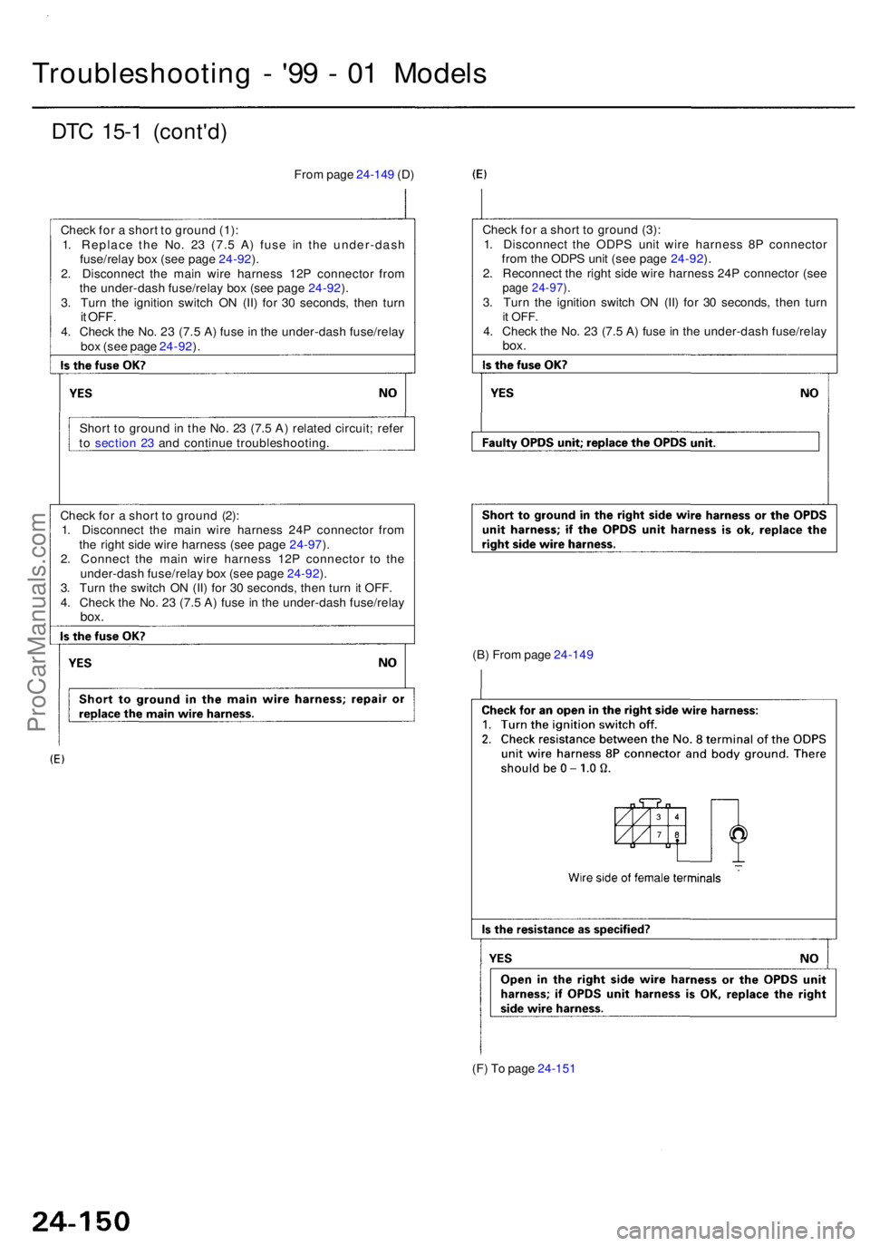
Troubleshooting - '9 9 - 0 1 Model s
DTC 15- 1 (cont'd )
From pag e 24-14 9 (D )
Chec k fo r a shor t t o groun d (1) :
1 . Replac e th e No . 2 3 (7. 5 A ) fus e i n th e under-das h
fuse/rela y bo x (se e pag e 24-92 ).
2 . Disconnec t th e mai n wir e harnes s 12 P connecto r fro m
th e under-das h fuse/rela y bo x (se e pag e 24-92 ).
3 . Tur n th e ignitio n switc h O N (II ) fo r 3 0 seconds , the n tur n
it OFF .4. Chec k th e No . 2 3 (7. 5 A ) fus e in th e under-das h fuse/rela y
bo x (se e pag e 24-92 ).
Shor t t o groun d in th e No . 2 3 (7. 5 A ) relate d circuit ; refe r
t o sectio n 2 3 an d continu e troubleshooting . Chec
k fo r a shor t t o groun d (3) :
1 . Disconnec t th e ODP S uni t wir e harnes s 8 P connecto r
fro m th e ODP S uni t (se e pag e 24-92 ).
2 . Reconnec t th e righ t sid e wir e harnes s 24 P connecto r (se e
page 24-97 ).3 . Tur n th e ignitio n switc h O N (II ) fo r 3 0 seconds , the n tur nit OFF .4. Chec k th e No . 2 3 (7. 5 A ) fus e in th e under-das h fuse/rela ybox.
Chec k fo r a shor t t o groun d (2) :
1 . Disconnec t th e mai n wir e harnes s 24 P connecto r fro m
th e righ t sid e wir e harnes s (se e pag e 24-97 ).
2 . Connec t th e mai n wir e harnes s 12 P connecto r t o th e
under-das h fuse/rela y bo x (se e pag e 24-92 ).
3 . Tur n th e switc h O N (II ) fo r 3 0 seconds , the n tur n i t OFF .
4 . Chec k th e No . 2 3 (7. 5 A ) fus e in th e under-das h fuse/rela y
box.
(B) Fro m pag e 24-14 9
(F ) T o pag e 24-15 1
ProCarManuals.com