engine ACURA RL KA9 1996 Service Repair Manual
[x] Cancel search | Manufacturer: ACURA, Model Year: 1996, Model line: RL KA9, Model: ACURA RL KA9 1996Pages: 1954, PDF Size: 61.44 MB
Page 1198 of 1954
Diagnostic Troubl e Cod e (DTC )
Diagnosti c Troubl e Cod e (DTC ) Indicatio n
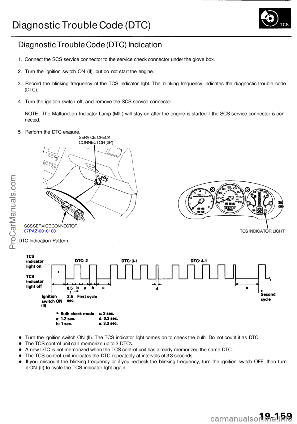
1. Connec t th e SC S servic e connecto r t o th e servic e chec k connecto r unde r th e glov e box .
2 . Tur n th e ignitio n switc h O N (II) , bu t d o no t star t th e engine .
3 . Recor d th e blinkin g frequenc y o f th e TC S indicato r light . Th e blinkin g frequenc y indicate s th e diagnosti c troubl e cod e
(DTC) .
4. Tur n th e ignitio n switc h off , an d remov e th e SC S servic e connector .
NOTE : Th e Malfunctio n Indicato r Lam p (MIL ) wil l sta y o n afte r th e engin e is starte d if th e SC S servic e connecto r i s con -
nected .
5 . Perfor m th e DT C erasure .
SERVIC E CHEC KCONNECTO R (2P )
SC S SERVIC E CONNECTO R
07PAZ-001010 0
DTC Indicatio n Patter n
TCS INDICATO R LIGH T
Turn th e ignitio n switc h O N (II) . Th e TC S indicato r ligh t come s o n to chec k th e bulb . D o no t coun t i t a s DTC .
Th e TC S contro l uni t ca n memoriz e u p to 3 DTCs .
A ne w DT C is no t memorize d whe n th e TC S contro l uni t ha s alread y memorize d th e sam e DTC .
Th e TC S contro l uni t indicate s th e DT C repeatedl y a t interval s o f 3. 3 seconds .
I f yo u miscoun t th e blinkin g frequenc y o r i f yo u rechec k th e blinkin g frequency , tur n th e ignitio n switc h OFF , the n tur n
i t O N (II ) t o cycl e th e TC S indicato r ligh t again .
ProCarManuals.com
Page 1209 of 1954
Troubleshooting
Steering Angl e Senso r (cont'd )
From pag e 19-16 9
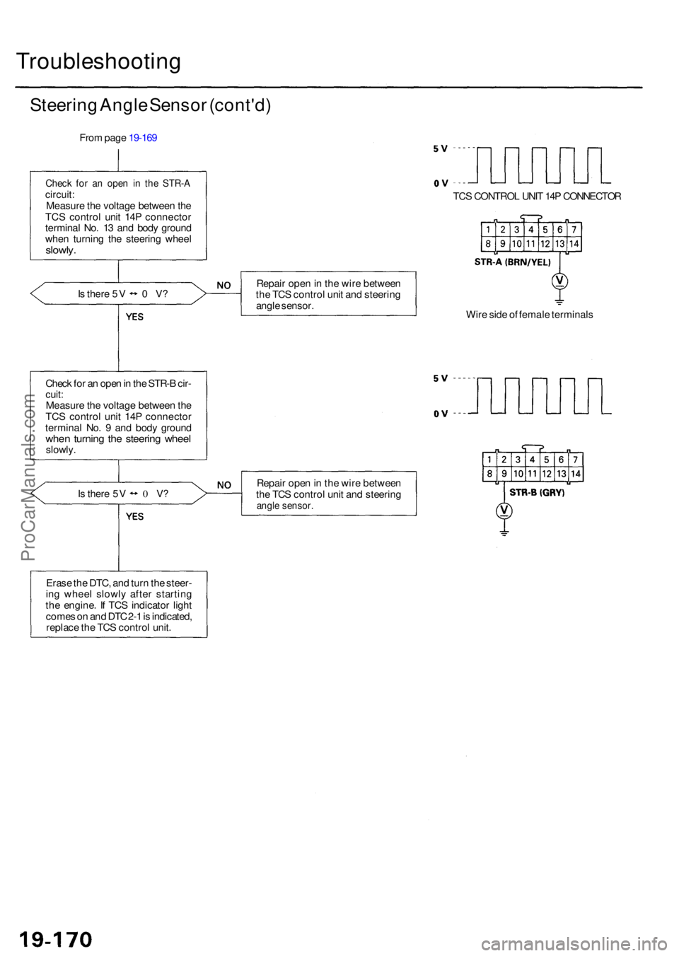
Chec k fo r a n ope n i n th e STR- Acircuit:Measur e th e voltag e betwee n th e
TC S contro l uni t 14 P connecto r
termina l No . 1 3 an d bod y groun d
whe n turnin g th e steerin g whee l
slowly.
Is ther e 5 V 0 V?
Chec k fo r a n ope n in th e STR- B cir -
cuit :Measur e th e voltag e betwee n th e
TC S contro l uni t 14 P connecto r
termina l No . 9 an d bod y groun d
when turnin g th e steerin g whee lslowly .
Is ther e 5 V 0 V? Repai
r ope n in th e wir e betwee n
th e TC S contro l uni t an d steerin g
angl e sensor .
Wire sid e o f femal e terminal s
Repai r ope n in th e wir e betwee n
th e TC S contro l uni t an d steerin gangle sensor .
Erase th e DTC , an d tur n th e steer -
in g whee l slowl y afte r startin g
th e engine . I f TC S indicato r ligh t
come s o n an d DT C 2- 1 is indicated ,
replac e th e TC S contro l unit . TC
S CONTRO L UNI T 14 P CONNECTO R
ProCarManuals.com
Page 1211 of 1954
Troubleshooting
TC-INH Signal (No PGM-FI DTC is indicated)
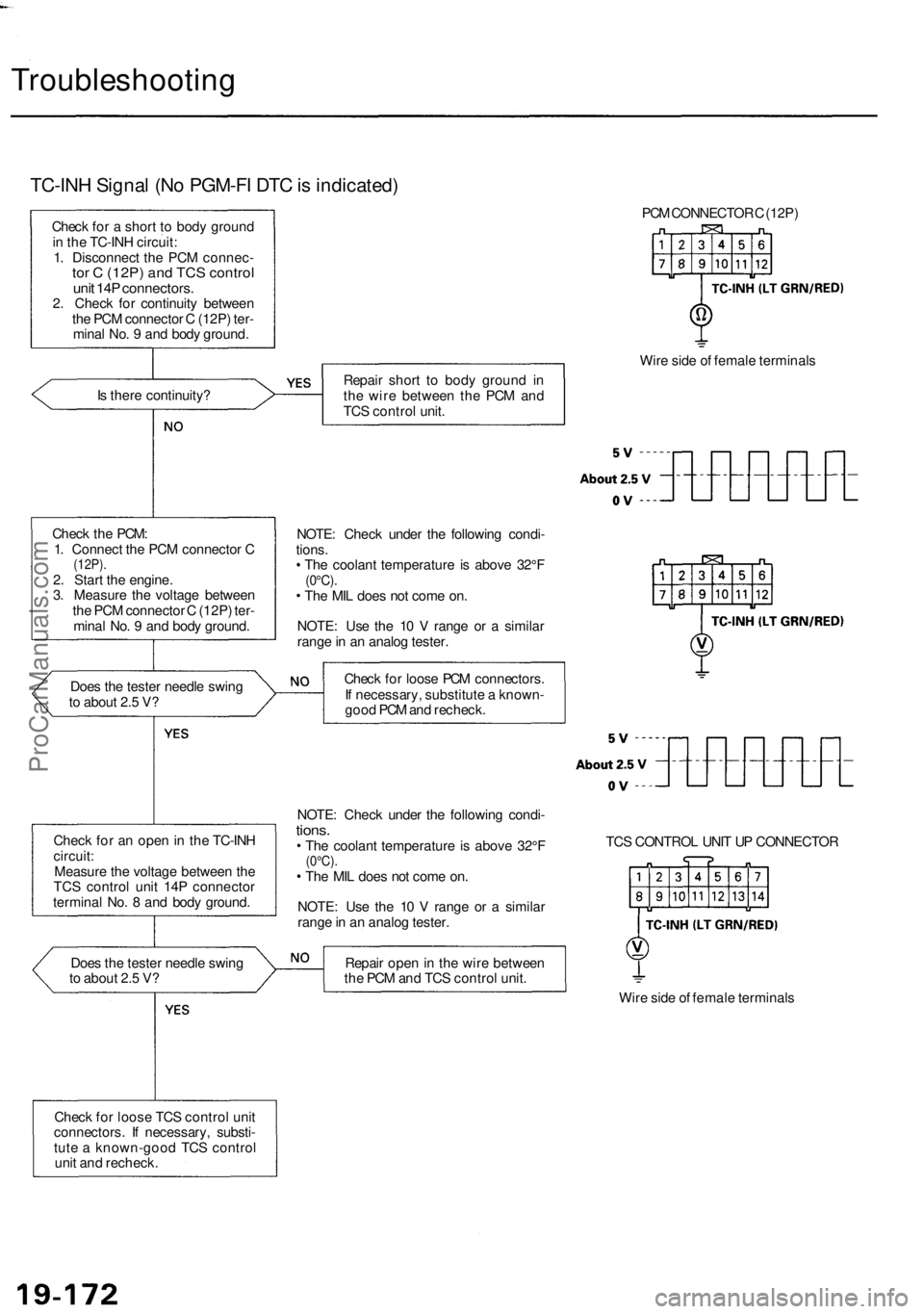
Check for a short to body ground
in the TC-INH circuit:
1. Disconnect the PCM connec-
tor C (12P) and TCS control
unit 14P connectors.
2. Check for continuity between
the PCM connector C (12P) ter-
minal No. 9 and body ground.
Is there continuity?
Check the PCM:
1. Connect the PCM connector C
(12P).
2. Start the engine.
3. Measure the voltage between
the PCM connector C (12P) ter-
minal No. 9 and body ground.
Does the tester needle swing
to about 2.5 V?
Check for an open in the TC-INH
circuit:
Measure the voltage between the
TCS control unit 14P connector
terminal No. 8 and body ground.
Does the tester needle swing
to about 2.5 V?
Check for loose TCS control unit
connectors. If necessary, substi-
tute a known-good TCS control
unit and recheck.
PCM CONNECTOR C (12P)
Repair short to body ground in
the wire between the PCM and
TCS control unit.
Wire side of female terminals
NOTE: Check under the following condi-
tions.
The coolant temperature is above 32°F
(0°C).
The MIL does not come on.
NOTE: Use the 10 V range or a similar
range in an analog tester.
Check for loose PCM connectors.
If necessary, substitute a known-
good PCM and recheck.
NOTE: Check under the following condi-
tions.
The coolant temperature is above 32°F
(0°C).
The MIL does not come on.
NOTE: Use the 10 V range or a similar
range in an analog tester.
TCS CONTROL UNIT UP CONNECTOR
Repair open in the wire between
the PCM and TCS control unit.
Wire side of female terminalsProCarManuals.com
Page 1212 of 1954
PGM-FI DTC : 3 5 (TC-ST B signa l doe s no t matc h TC-F C signal )
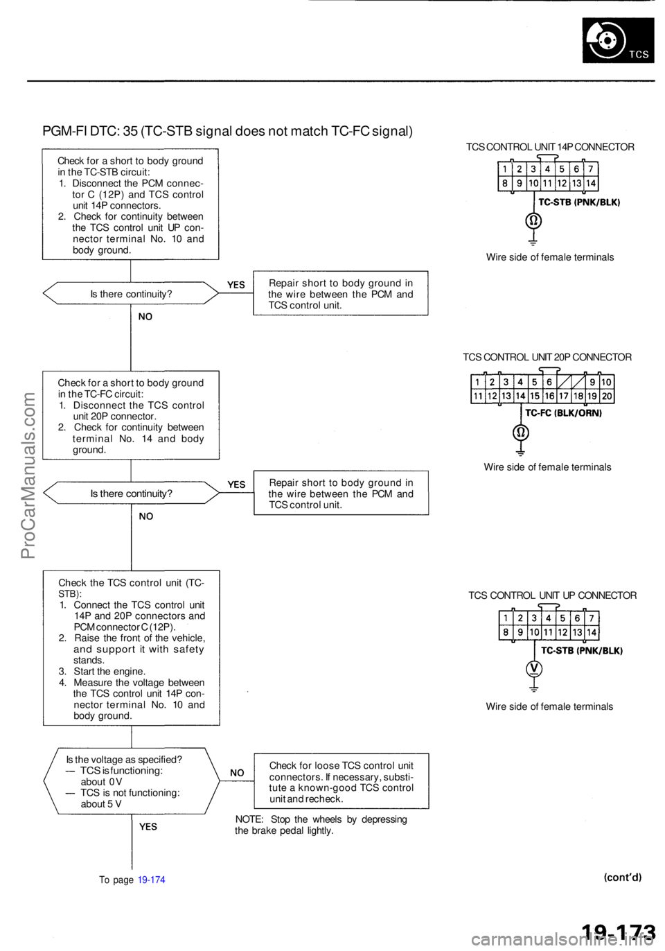
Check fo r a shor t t o bod y groun d
i n th e TC-ST B circuit :
1 . Disconnec t th e PC M connec -
to r C (12P ) an d TC S contro l
uni t 14 P connectors .
2 . Chec k fo r continuit y betwee n
th e TC S contro l uni t U P con -
necto r termina l No . 1 0 an d
bod y ground . TC
S CONTRO L UNI T 14 P CONNECTO R
Wir e sid e o f femal e terminal s
I s ther e continuity ? Repai
r shor t t o bod y groun d in
th e wir e betwee n th e PC M an d
TC S contro l unit .
TCS CONTRO L UNI T 20 P CONNECTO R
Chec k fo r a shor t t o bod y groun d
i n th e TC-F C circuit :
1 . Disconnec t th e TC S contro l
uni t 20 P connector .
2 . Chec k fo r continuit y betwee n
termina l No . 1 4 an d bod y
ground .
Is ther e continuity ?Repair shor t t o bod y groun d in
th e wir e betwee n th e PC M an d
TC S contro l unit . Wir
e sid e o f femal e terminal s
Chec k th e TC S contro l uni t (TC -
STB) :1. Connec t th e TC S contro l uni t
14 P an d 20 P connector s an d
PC M connecto r C (12P) .
2 . Rais e th e fron t o f th e vehicle ,
and suppor t i t wit h safet ystands.
3 . Star t th e engine .
4 . Measur e th e voltag e betwee n
th e TC S contro l uni t 14 P con -
necto r termina l No . 1 0 an d
bod y ground . TC
S CONTRO L UNI T U P CONNECTO R
Wir e sid e o f femal e terminal s
I s th e voltag e a s specified ?
TCS is functioning :about 0 V
TC S is no t functioning :
abou t 5 V Chec
k fo r loos e TC S contro l uni t
connectors . I f necessary , substi -
tut e a known-goo d TC S contro l
uni t an d recheck .
To pag e 19-17 4
NOTE : Sto p th e wheel s b y depressin g
th e brak e peda l lightly .
ProCarManuals.com
Page 1215 of 1954
Troubleshooting
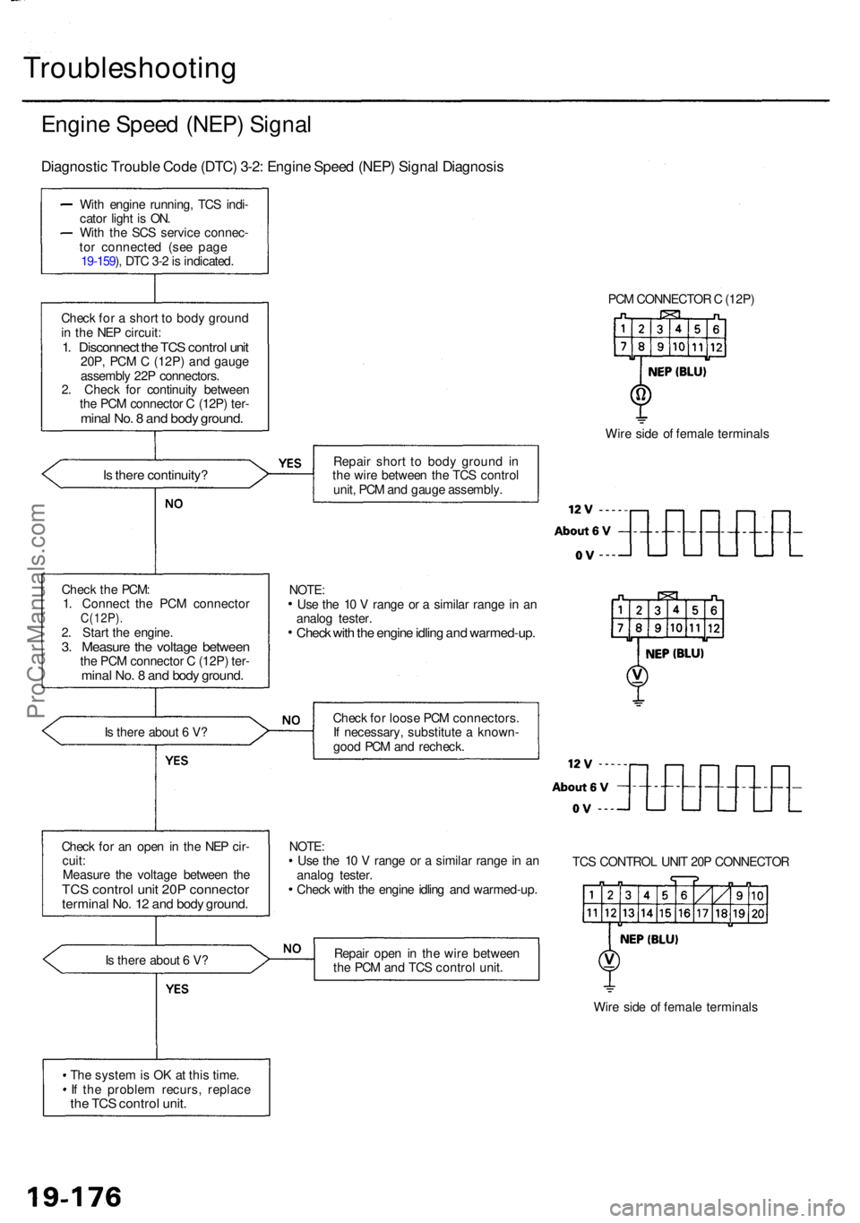
Engine Spee d (NEP ) Signa l
Diagnosti c Troubl e Cod e (DTC ) 3-2 : Engin e Spee d (NEP ) Signa l Diagnosi s
With engin e running , TC S indi -
cato r ligh t i s ON .
Wit h th e SC S servic e connec -
to r connecte d (se e pag e
19-159 ), DT C 3- 2 is indicated .
Chec k fo r a shor t t o bod y groun d
i n th e NE P circuit :
1. Disconnec t th e TC S contro l uni t20P , PC M C (12P ) an d gaug e
assembl y 22 P connectors .
2 . Chec k fo r continuit y betwee n
th e PC M connecto r C (12P ) ter -
mina l No . 8 an d bod y ground .
Is ther e continuity ?
Is ther e abou t 6 V ?
Chec k fo r a n ope n in th e NE P cir -
cuit :
Measur e th e voltag e betwee n th e
TC S contro l uni t 20 P connecto rterminal No . 1 2 an d bod y ground .
Is ther e abou t 6 V ?
Th e syste m is O K a t thi s time .
I f th e proble m recurs , replac e
the TC S contro l unit .
PCM CONNECTO R C (12P )
Wir e sid e o f femal e terminal s
Repai r shor t t o bod y groun d i n
th e wir e betwee n th e TC S contro l
unit , PC M an d gaug e assembly .
Chec k fo r loos e PC M connectors .
I f necessary , substitut e a known -
goo d PC M an d recheck .
NOTE :
Us e th e 1 0 V rang e o r a simila r rang e in a n
analo g tester .
Chec k wit h th e engin e idlin g an d warmed-up .TC
S CONTRO L UNI T 20 P CONNECTO R
Repai r ope n in th e wir e betwee n
th e PC M an d TC S contro l unit .
Wire sid e o f femal e terminal s
Chec
k th e PCM :
1 . Connec t th e PC M connecto r
C(12P).2. Star t th e engine .3. Measur e th e voltag e betwee nthe PC M connecto r C (12P ) ter -mina l No . 8 an d bod y ground .
Use th e 1 0 V rang e o r a simila r rang e in a n
analo g tester .
Check wit h th e engin e idlin g an d warmed-up .
NOTE:
ProCarManuals.com
Page 1223 of 1954
Troubleshooting
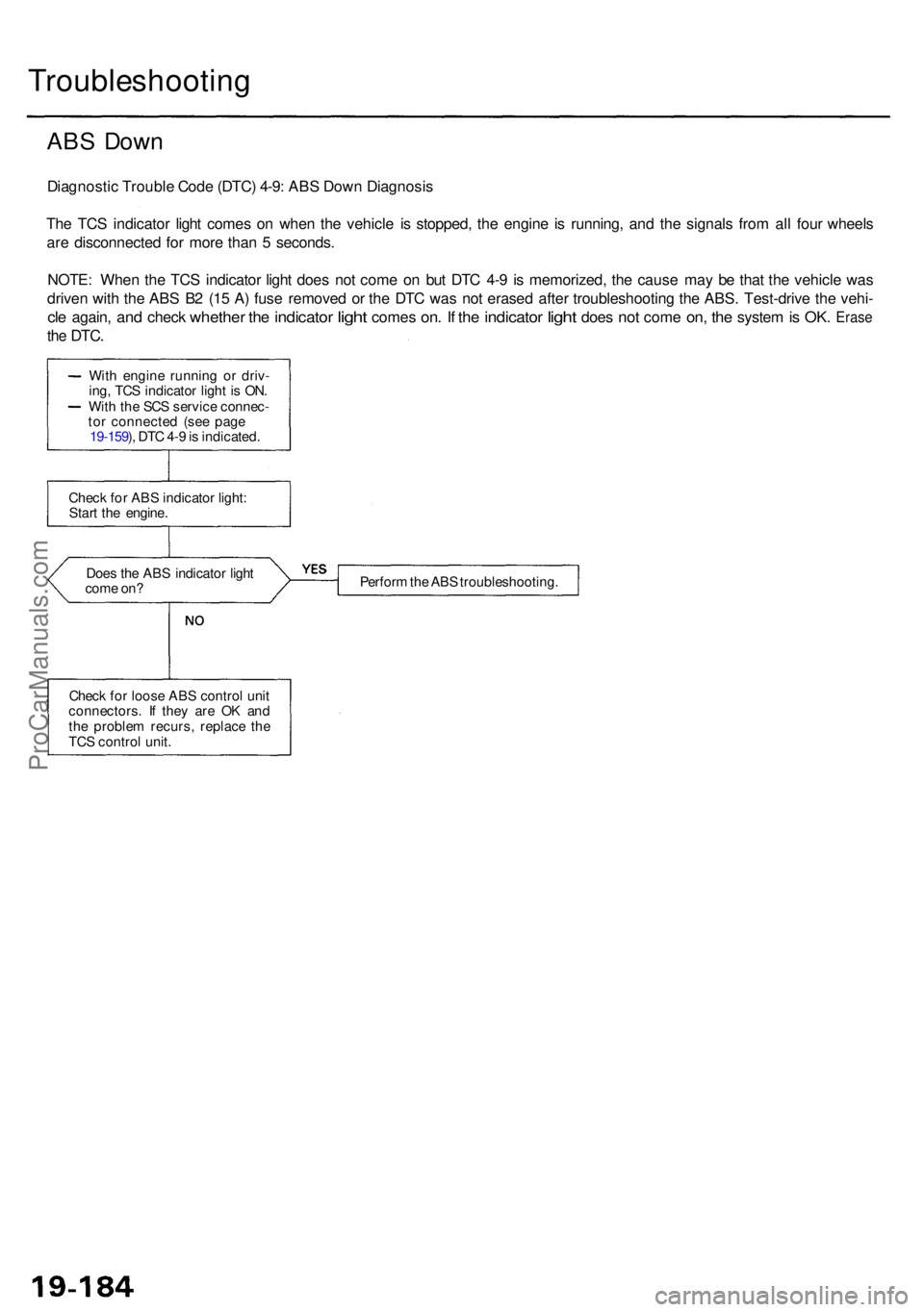
ABS Dow n
Diagnosti c Troubl e Cod e (DTC ) 4-9 : AB S Dow n Diagnosi s
Th e TC S indicato r ligh t come s o n whe n th e vehicl e i s stopped , th e engin e i s running , an d th e signal s fro m al l fou r wheel s
ar e disconnecte d fo r mor e tha n 5 seconds .
NOTE : Whe n th e TC S indicato r ligh t doe s no t com e o n bu t DT C 4- 9 i s memorized , th e caus e ma y b e tha t th e vehicl e wa s
drive n wit h th e AB S B 2 (1 5 A ) fus e remove d o r th e DT C wa s no t erase d afte r troubleshootin g th e ABS . Test-driv e th e vehi -
cle again , and chec k whethe r the indicato r light come s on. I f th e indicato r light doe s not com e on, th e syste m is OK . Eras e
the DTC .
Does th e AB S indicato r ligh t
com e on ? Perfor
m th e AB S troubleshooting .
Chec k fo r loos e AB S contro l uni t
connectors . I f the y ar e O K an d
th e proble m recurs , replac e th e
TC S contro l unit .
Chec
k fo r AB S indicato r light :
Star t th e engine .
Wit
h engin e runnin g o r driv -
ing , TC S indicato r ligh t i s ON .
Wit h th e SC S servic e connec -
to r connecte d (se e pag e
19-159 ), DT C 4- 9 is indicated .
ProCarManuals.com
Page 1225 of 1954
Troubleshooting
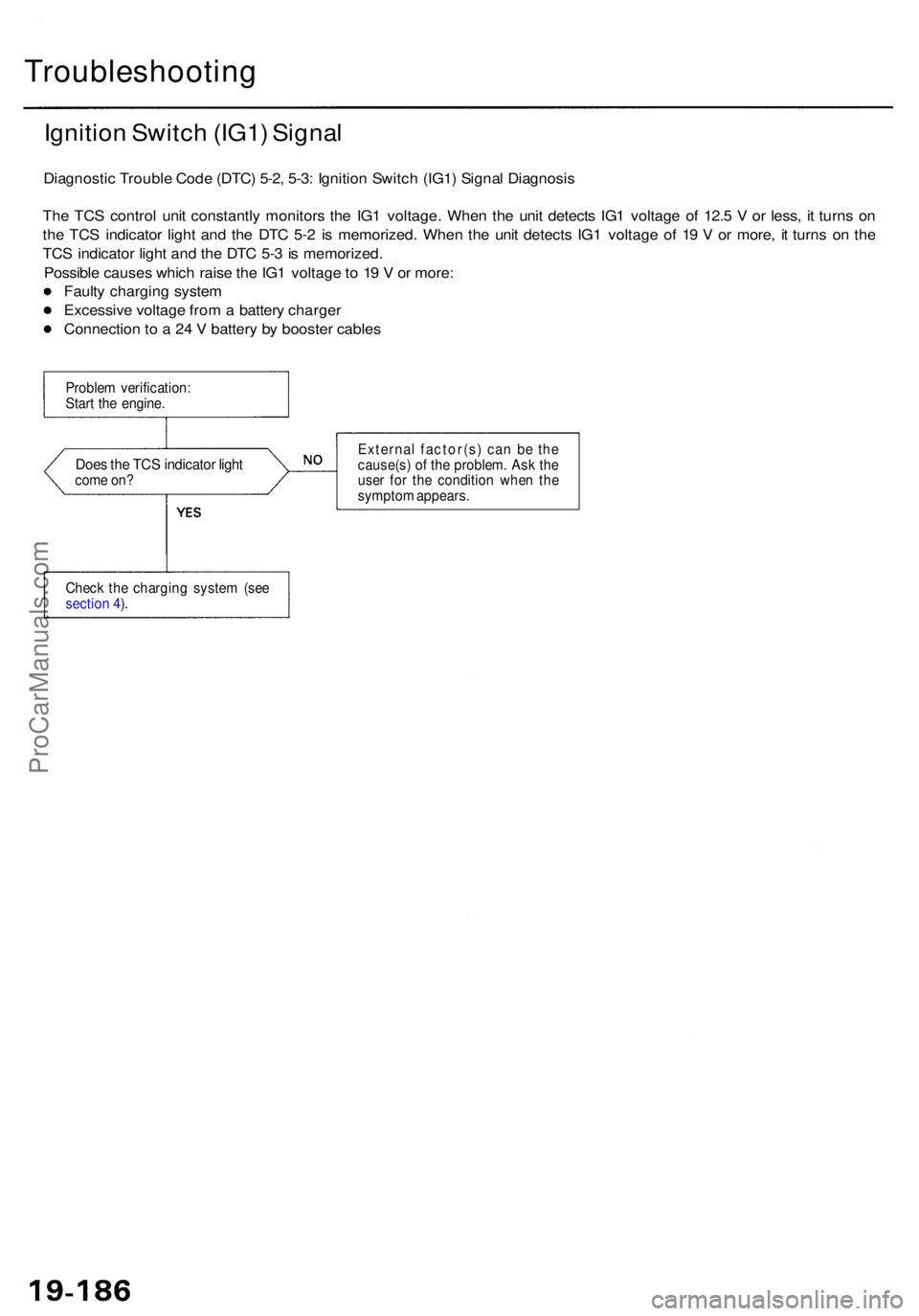
Ignition Switc h (IG1 ) Signa l
Diagnosti c Troubl e Cod e (DTC ) 5-2 , 5-3 : Ignitio n Switc h (IG1 ) Signa l Diagnosi s
Th e TC S contro l uni t constantl y monitor s th e IG 1 voltage . Whe n th e uni t detect s IG 1 voltag e o f 12. 5 V or less , i t turn s o n
th e TC S indicato r ligh t an d th e DT C 5- 2 i s memorized . Whe n th e uni t detect s IG 1 voltag e o f 1 9 V or more , i t turn s o n th e
TC S indicato r ligh t an d th e DT C 5- 3 is memorized .
Possibl e cause s whic h rais e th e IG 1 voltag e to 1 9 V or more :
Fault y chargin g syste m
Excessiv e voltag e fro m a batter y charge r
Connectio n t o a 24 V batter y b y booste r cable s
Proble m verification :
Star t th e engine .
Does th e TC S indicato r ligh tcom e on ? Externa
l factor(s ) ca n b e th e
cause(s ) o f th e problem . As k th e
use r fo r th e conditio n whe n th e
sympto m appears .
Chec k th e chargin g syste m (se e
sectio n 4 ).
ProCarManuals.com
Page 1226 of 1954
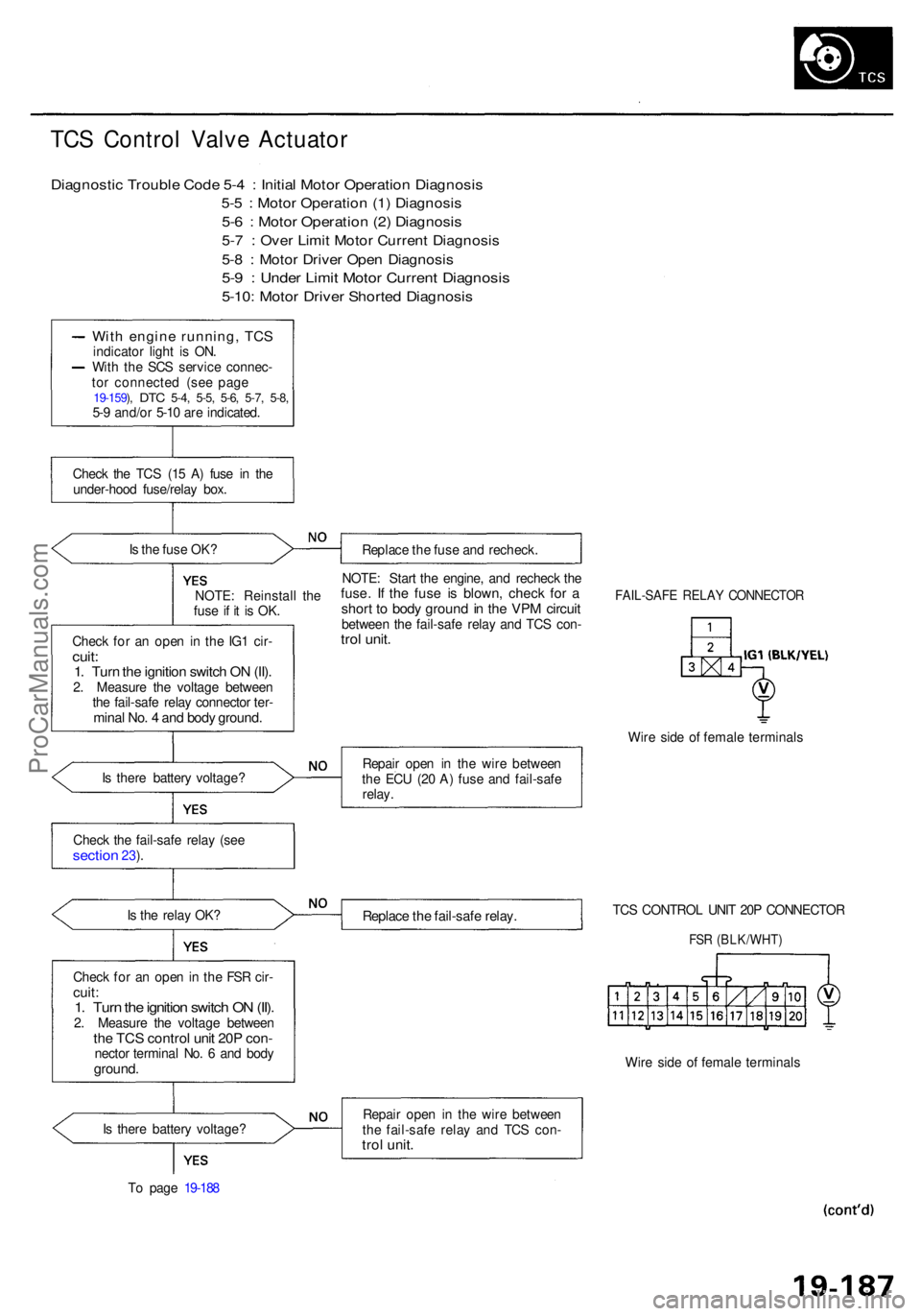
TCS Contro l Valv e Actuato r
Diagnosti c Troubl e Cod e 5- 4 : Initia l Moto r Operatio n Diagnosi s
5-5 : Moto r Operatio n (1 ) Diagnosi s
5-6 : Moto r Operatio n (2 ) Diagnosi s
5-7 : Ove r Limi t Moto r Curren t Diagnosi s
5-8 : Moto r Drive r Ope n Diagnosi s
5-9 : Unde r Limi t Moto r Curren t Diagnosi s
5-10: Moto r Drive r Shorte d Diagnosi s
With engin e running , TC Sindicato r ligh t i s ON .
Wit h th e SC S servic e connec -
to r connecte d (se e pag e
19-159 ), DT C 5-4 , 5-5 , 5-6 , 5-7 , 5-8 ,5-9 and/o r 5-1 0 ar e indicated .
Chec k th e TC S (1 5 A ) fus e i n th e
under-hoo d fuse/rela y box .
I s th e fus e OK ?
Replace th e fus e an d recheck .
NOTE : Reinstal l th e
fus e i f i t i s OK .
Chec k fo r a n ope n i n th e IG 1 cir -
cuit:1. Tur n th e ignitio n switc h O N (II) .2. Measur e th e voltag e betwee n
th e fail-saf e rela y connecto r ter -
mina l No . 4 an d bod y ground .
NOTE: Star t th e engine , an d rechec k th efuse . I f th e fus e i s blown , chec k fo r ashor t t o bod y groun d in th e VP M circui tbetwee n th e fail-saf e rela y an d TC S con -trol unit .
FAIL-SAF E RELA Y CONNECTO R
Wire sid e o f femal e terminal s
I s ther e batter y voltage ? Repai
r ope n i n th e wir e betwee n
th e EC U (2 0 A ) fus e an d fail-saf e
relay .
Chec k th e fail-saf e rela y (se e
sectio n 23).
I s th e rela y OK ?
Replac e th e fail-saf e relay .TCS CONTRO L UNI T 20 P CONNECTO R
FSR (BLK/WHT )
Check fo r a n ope n in th e FS R cir -cuit :1. Tur n th e ignitio n switc h O N (II) .2. Measur e th e voltag e betwee nthe TC S contro l uni t 20 P con -necto r termina l No . 6 an d bod yground .Wire sid e o f femal e terminal s
I s ther e batter y voltage ?
T o pag e 19-18 8 Repai
r ope n i n th e wir e betwee n
th e fail-saf e rela y an d TC S con -
trol unit .
ProCarManuals.com
Page 1230 of 1954
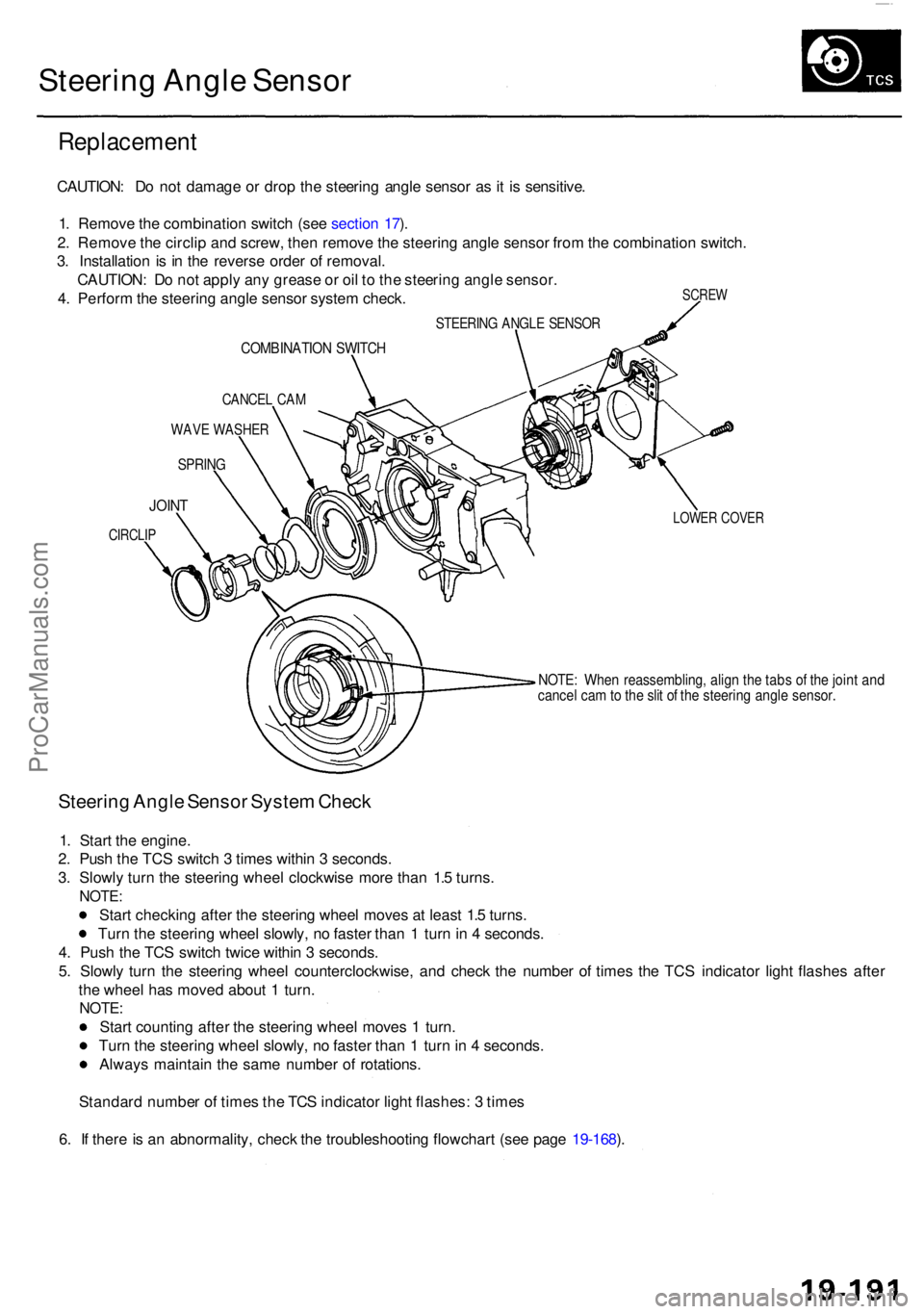
Steering Angl e Senso r
Replacemen t
SCREW
CAUTION : D o no t damag e o r dro p th e steerin g angl e senso r a s it i s sensitive .
1 . Remov e th e combinatio n switc h (se e sectio n 17 ).
2 . Remov e th e circli p an d screw , the n remov e th e steerin g angl e senso r fro m th e combinatio n switch .
3 . Installatio n i s i n th e revers e orde r o f removal .
CAUTION : D o no t appl y an y greas e o r oi l t o th e steerin g angl e sensor .
4 . Perfor m th e steerin g angl e senso r syste m check .
STEERIN G ANGL E SENSO R
COMBINATIO N SWITC H
CANCE L CA M
WAV E WASHE R
SPRING
LOWER COVE RJOINT
CIRCLI P
NOTE: Whe n reassembling , alig n th e tab s o f th e join t an dcance l ca m to th e sli t o f th e steerin g angl e sensor .
Steering Angl e Senso r Syste m Chec k
1. Star t th e engine .
2 . Pus h th e TC S switc h 3 time s withi n 3 seconds .
3 . Slowl y tur n th e steerin g whee l clockwis e mor e tha n 1. 5 turns .
NOTE :
Start checkin g afte r th e steerin g whee l move s a t leas t 1. 5 turns .
Tur n th e steerin g whee l slowly , n o faste r tha n 1 tur n in 4 seconds .
4 . Pus h th e TC S switc h twic e withi n 3 seconds .
5 . Slowl y tur n th e steerin g whee l counterclockwise , an d chec k th e numbe r o f time s th e TC S indicato r ligh t flashe s afte r
th e whee l ha s move d abou t 1 turn .
NOTE :
Start countin g afte r th e steerin g whee l move s 1 turn .
Tur n th e steerin g whee l slowly , n o faste r tha n 1 tur n in 4 seconds .
Alway s maintai n th e sam e numbe r o f rotations .
Standar d numbe r o f time s th e TC S indicato r ligh t flashes : 3 time s
6 . I f ther e is a n abnormality , chec k th e troubleshootin g flowchar t (se e pag e 19-168 ).
ProCarManuals.com
Page 1239 of 1954
Troubleshooting Precaution s
System Indicator s
If th e syste m is OK , th e AB S indicato r goe s of f onc e afte r turnin g th e ignitio n switc h O N (II ) withou t startin g th e engine ,
an d the n com e o n agai n an d g o of f severa l second s late r afte r startin g th e engine . Thi s occur s becaus e th e VS A contro l
uni t i s turne d o n b y th e IG 2 powe r source .
Th e AB S indicato r o r VS A syste m indicato r come s o n whe n th e VS A contro l uni t detect s a proble m in th e system .
Th e AB S indicato r o r VS A syste m indicato r wil l als o com e o n unde r thes e conditions , eve n thoug h th e syste m is oper -
atin g properly :
— Th e vehicl e goe s int o a spi n
— Th e AB S continue s t o operat e fo r a lon g tim e
— Th e vehicl e is subjecte d to a n electrica l signa l disturbanc e
I f ther e is a faul t i n th e PGM-F I system , onl y th e VS A syste m indicato r come s on .
Th e VS A Activatio n Indicato r wil l flas h whe n onl y th e driv e wheel s rotat e o r on e o f th e driv e wheel s is stuck . Whe n thi s
occurs , th e AB S indicato r an d VS A syste m indicato r d o no t com e on .
T o determin e th e actua l caus e o f th e problem , questio n th e custome r abou t th e problem , takin g thes e condition s int o con -
sideration .
Whe n a proble m is detecte d an d th e AB S o r VS A indicato r come s on , ther e ar e case s whe n th e indicato r stay s o n unti l
th e ignitio n switc h i s turne d OFF , an d case s whe n th e indicato r goe s of f automaticall y whe n th e syste m return s t o nor -
mal . Fo r DT C 6 1 an d 62 , th e indicato r goe s of f automaticall y whe n th e syste m return s t o normal . Fo r al l othe r codes ,
th e indicato r stay s o n unti l th e ignitio n switc h is turne d OFF .
Fo r DTC s 12 , 14 , 16 , 18 , 51 , 52 , 53 , 66 , 6 8 an d 84 , th e AB S indicato r goe s of f whe n th e vehicl e is drive n agai n an d th e
syste m is O K afte r th e ignitio n switc h is turne d fro m OF F to O N (II) . However , i f th e DT C is cleared , th e CP U reset s an d
th e indicato r goe s of f righ t afte r th e engin e is starte d if th e syste m is OK .
Th e AB S is no t operationa l whe n th e AB S indicato r i s ON ; th e VS A is no t operationa l whe n th e VS A indicato r i s ON .
Whe n th e VS A indicato r an d MI L ar e bot h ON , troubleshoo t th e PGM-F I syste m first .
Diagnosti c Troubl e Cod e (DTC )
Th e memor y ca n hol d an y numbe r o f DTCs . However , whe n th e sam e DT C is detecte d mor e tha n once , th e mor e recen t
DT C is writte n ove r th e earlie r one . Therefore , whe n th e sam e proble m is detecte d repeatedly , i t i s memorize d a s a sin -
gle DTC .
The DTC s ar e indicate d in ascendin g numbe r order , no t i n th e orde r the y occur .
Th e DTC s ar e memorize d in th e EEPRO M (non-volatil e memory) . Therefore , th e memorize d DTC s canno t b e cancele d
b y disconnectin g th e battery . Perfor m th e specifie d procedure s to clea r th e DTCs .
Self-diagnosi s
Self-diagnosis can be classifie d int o tw o categories :
— Initia l diagnosis : Performe d righ t afte r th e engin e start s an d unti l th e AB S o r VS A indicato r goe s off .
— Regula r diagnosis : Performe d righ t afte r th e initia l diagnosi s unti l th e ignitio n switc h is turne d OFF .
When a proble m is detecte d b y self-diagnosis , th e VS A contro l uni t shift s to fail-saf e mode .
Kickbac k
The pum p moto r operate s whe n th e AB S is functioning , an d th e flui d in th e reservoi r i s force d ou t t o th e maste r cylinder ,
causing kickbac k a t th e brak e pedal .
Pum p Moto r
Th e pum p moto r operate s whe n th e AB S is functioning .
The VS A contro l uni t check s th e pum p moto r operatio n durin g initia l diagnosi s whe n th e vehicl e is started .
You ma y hea r th e moto r operat e a t thi s time , bu t i t i s normal .
Brak e Flui d Replacement/Ai r Bleedin g
Brak e flui d replacemen t an d ai r bleedin g procedure s ar e identica l t o th e procedure s us e o n vehicle s no t equippe d wit h
VSA . T o eas e bleeding , star t wit h th e fron t wheels .
ProCarManuals.com