engine ACURA RL KA9 1996 Service Repair Manual
[x] Cancel search | Manufacturer: ACURA, Model Year: 1996, Model line: RL KA9, Model: ACURA RL KA9 1996Pages: 1954, PDF Size: 61.44 MB
Page 1144 of 1954
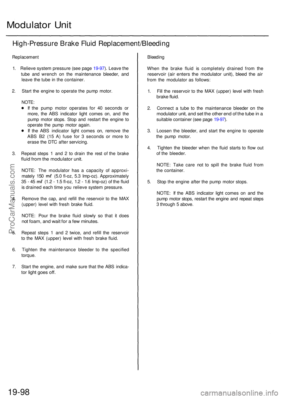
Modulator Uni t
High-Pressur e Brak e Flui d Replacement/Bleedin g
Replacement
1. Reliev e syste m pressur e (se e pag e 19-97 ). Leav e th e
tub e an d wrenc h o n th e maintenanc e bleeder , an d
leav e th e tub e in th e container .
2 . Star t th e engin e t o operat e th e pum p motor .
NOTE:
If th e pum p moto r operate s fo r 4 0 second s o r
more , th e AB S indicato r ligh t come s on , an d th e
pum p moto r stops . Sto p an d restar t th e engin e t o
operat e th e pum p moto r again .
I f th e AB S indicator light come s on , remov e th e
AB S B 2 (1 5 A ) fus e fo r 3 second s o r mor e t o
eras e th e DT C afte r servicing .
3 . Repea t step s 1 an d 2 to drai n th e res t o f th e brak e
fluid fro m th e modulato r unit .
NOTE : Th e modulato r ha s a capacit y o f approxi -
mately 15 0 (5. 0 fl-oz , 5. 3 Imp-oz) . Approximatel y
35 - 4 5 (1. 2 - 1. 5 fl-oz , 1. 2 - 1. 6 Imp-oz ) o f th e flui d
i s draine d eac h tim e yo u reliev e syste m pressure .
4 . Remov e th e cap , an d refil l th e reservoi r t o th e MA X
(upper ) leve l wit h fres h brak e fluid .
NOTE : Pou r th e brak e flui d slowl y s o tha t i t doe s
not foam , an d wai t fo r a fe w minutes .
5. Repea t step s 1 an d 2 twice , an d refil l th e reservoi r
t o th e MA X (upper ) leve l wit h fres h brak e fluid .
6 . Tighte n th e maintenanc e bleede r t o th e specifie d
torque .
7 . Star t th e engine , an d mak e sur e tha t th e AB S indica -
tor ligh t goe s off .
Bleedin g
Whe n th e brak e flui d i s completel y draine d fro m th e
reservoi r (ai r enter s th e modulato r unit) , blee d th e ai r
from th e modulato r a s follows :
1 . Fil l th e reservoi r t o th e MA X (upper ) leve l wit h fres h
brake fluid .
2. Connec t a tub e t o th e maintenanc e bleede r o n th e
modulato r unit , an d se t th e othe r en d o f th e tub e in a
suitabl e containe r (se e pag e 19-97 ).
3 . Loose n th e bleeder , an d star t th e engin e t o operat e
th e pum p motor .
4 . Tighte n th e bleede r whe n th e flui d start s t o flo w ou t
o f th e bleeder .
NOTE : Tak e car e no t t o spil l th e brak e flui d fro m
th e container .
5 . Sto p th e engin e afte r th e pum p moto r stops .
NOTE : I f th e AB S indicato r ligh t come s o n an d th e
pum p moto r stops , restar t th e engin e an d repea t step s
3 throug h 5 above .
19-98ProCarManuals.com
Page 1154 of 1954
Self-diagnosis
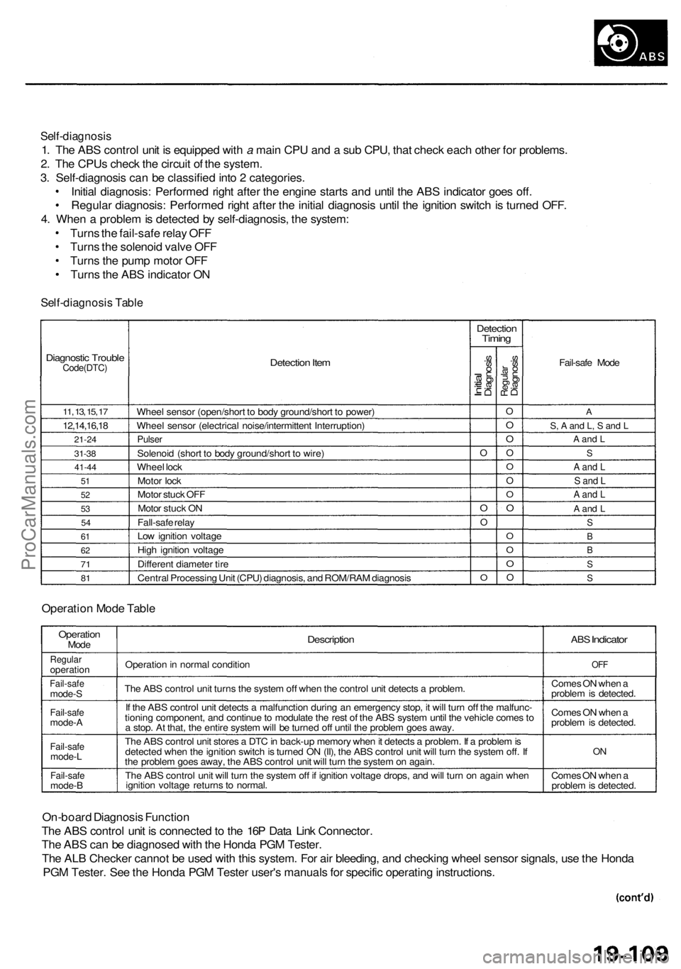
1. The ABS control unit is equipped with a main CPU and a sub CPU, that check each other for problems.
2. The CPUs check the circuit of the system.
3. Self-diagnosis can be classified into 2 categories.
Initial diagnosis: Performed right after the engine starts and until the ABS indicator goes off.
Regular diagnosis: Performed right after the initial diagnosis until the ignition switch is turned OFF.
4. When a problem is detected by self-diagnosis, the system:
Turns the fail-safe relay OFF
Turns the solenoid valve OFF
Turns the pump motor OFF
Turns the ABS indicator ON
Self-diagnosis Table
Diagnostic Trouble
Code(DTC)
11, 13, 15, 17
12,14,16,18
21-24
31-38
41-44
51
52
53
54
61
62
71
81
Detection Item
Wheel sensor (open/short to body ground/short to power)
Wheel sensor (electrical noise/intermittent Interruption)
Pulser
Solenoid (short to body ground/short to wire)
Wheel lock
Motor lock
Motor stuck OFF
Motor stuck ON
Fall-safe relay
Low ignition voltage
High ignition voltage
Different diameter tire
Central Processing Unit (CPU) diagnosis, and ROM/RAM diagnosis
Detection
Timing
Initial
Diagnosis
O
O
O
O
Regular
Diagnosis
O
O
O
O
O
O
O
O
O
O
O
O
Fail-safe Mode
A
S, A and L, S and L
A and L
S
A and L
S and L
A and L
A and L
S
B
B
S
S
Operation Mode Table
Operation
Mode
Regular
operation
Fail-safe
mode-S
Fail-safe
mode-A
Fail-safe
mode-L
Fail-safe
mode-B
Description
Operation in normal condition
The ABS control unit turns the system off when the control unit detects a problem.
If the ABS control unit detects a malfunction during an emergency stop, it will turn off the malfunc-
tioning component, and continue to modulate the rest of the ABS system until the vehicle comes to
a stop. At that, the entire system will be turned off until the problem goes away.
The ABS control unit stores a DTC in back-up memory when it detects a problem. If a problem is
detected when the ignition switch is turned ON (II), the ABS control unit will turn the system off. If
the problem goes away, the ABS control unit will turn the system on again.
The ABS control unit will turn the system off if ignition voltage drops, and will turn on again when
ignition voltage returns to normal.
ABS
Indicator
OFF
Comes ON when a
problem is detected.
Comes ON when a
problem is detected.
ON
Comes ON when a
problem is detected.
On-board Diagnosis Function
The ABS control unit is connected to the 16P Data Link Connector.
The ABS can be diagnosed with the Honda PGM Tester.
The ALB Checker cannot be used with this system. For air bleeding, and checking wheel sensor signals, use the Honda
PGM Tester. See the Honda PGM Tester user's manuals for specific operating instructions.
ProCarManuals.com
Page 1160 of 1954
Troubleshooting Precautions
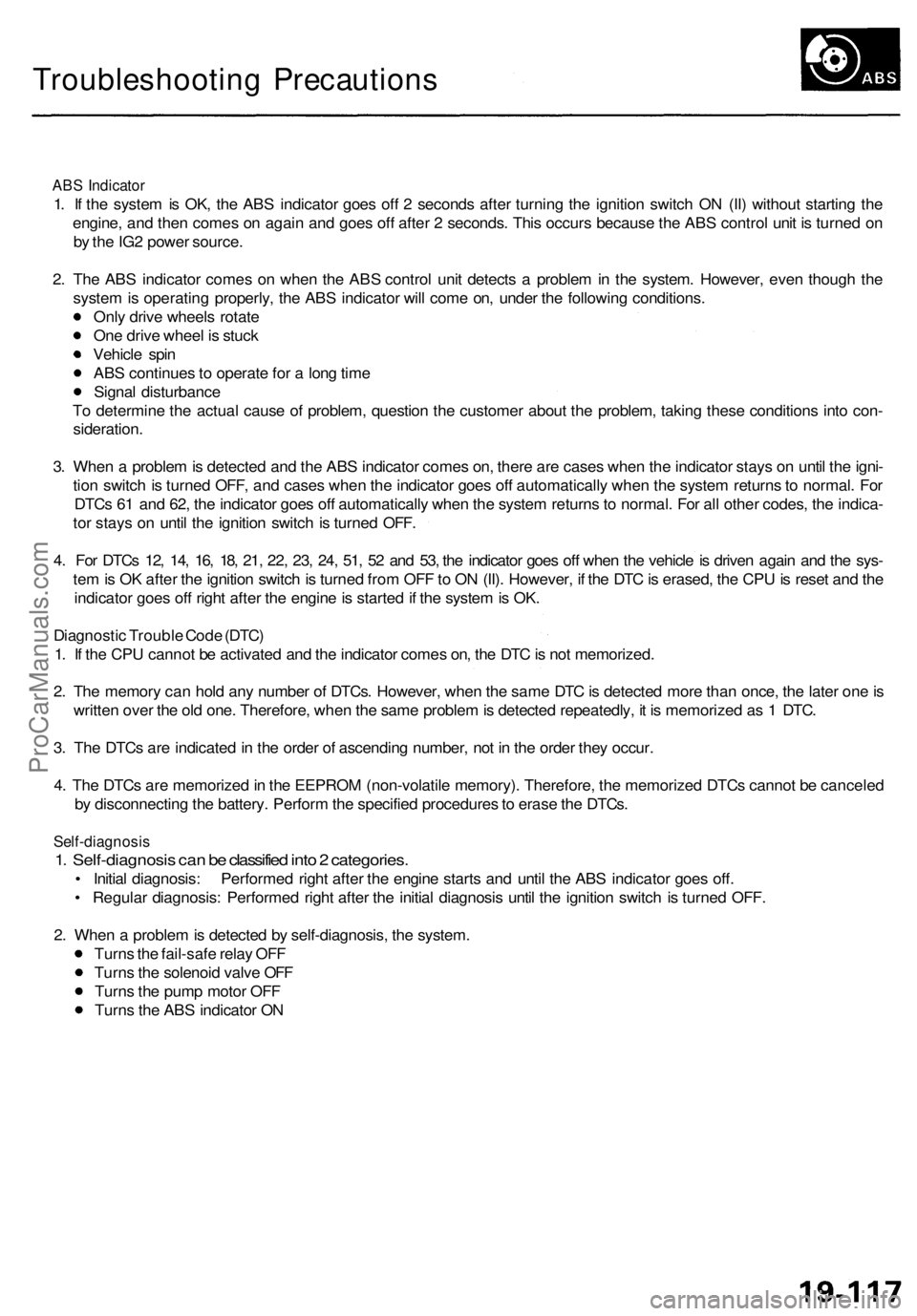
ABS Indicator
1. If the system is OK, the ABS indicator goes off 2 seconds after turning the ignition switch ON (II) without starting the
engine, and then comes on again and goes off after 2 seconds. This occurs because the ABS control unit is turned on
by the IG2 power source.
2. The ABS indicator comes on when the ABS control unit detects a problem in the system. However, even though the
system is operating properly, the ABS indicator will come on, under the following conditions.
Only drive wheels rotate
One drive wheel is stuck
Vehicle spin
ABS continues to operate for a long time
Signal disturbance
To determine the actual cause of problem, question the customer about the problem, taking these conditions into con-
sideration.
3. When a problem is detected and the ABS indicator comes on, there are cases when the indicator stays on until the igni-
tion switch is turned OFF, and cases when the indicator goes off automatically when the system returns to normal. For
DTCs 61 and 62, the indicator goes off automatically when the system returns to normal. For all other codes, the indica-
tor stays on until the ignition switch is turned OFF.
4. For DTCs 12, 14, 16, 18, 21, 22, 23, 24, 51, 52 and 53, the indicator goes off when the vehicle is driven again and the sys-
tem is OK after the ignition switch is turned from OFF to ON (II). However, if the DTC is erased, the CPU is reset and the
indicator goes off right after the engine is started if the system is OK.
Diagnostic Trouble Code (DTC)
1. If the CPU cannot be activated and the indicator comes on, the DTC is not memorized.
2. The memory can hold any number of DTCs. However, when the same DTC is detected more than once, the later one is
written over the old one. Therefore, when the same problem is detected repeatedly, it is memorized as 1 DTC.
3. The DTCs are indicated in the order of ascending number, not in the order they occur.
4. The DTCs are memorized in the EEPROM (non-volatile memory). Therefore, the memorized DTCs cannot be canceled
by disconnecting the battery. Perform the specified procedures to erase the DTCs.
Self-diagnosis
1. Self-diagnosis can be classified into 2 categories.
• Initial diagnosis: Performed right after the engine starts and until the ABS indicator goes off.
• Regular diagnosis: Performed right after the initial diagnosis until the ignition switch is turned OFF.
2. When a problem is detected by self-diagnosis, the system.
Turns the fail-safe relay OFF
Turns the solenoid valve OFF
Turns the pump motor OFF
Turns the ABS indicator ONProCarManuals.com
Page 1169 of 1954
Troubleshooting
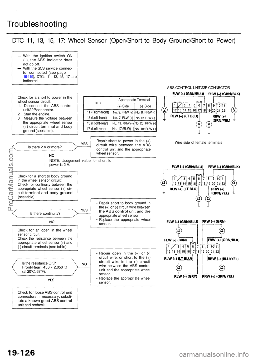
DTC 11 , 13 , 15 , 17 : Whee l Senso r (Open/Shor t t o Bod y Ground/Shor t t o Power )
With th e ignitio n switc h O N
(II) , th e AB S indicato r doe s
not g o off .With th e SC S servic e connec -
to r connecte d (se e pag e
19-119 ), DTC s 11 , 13 , 15 , 1 7 ar e
indicated .
Chec k fo r a shor t t o powe r i n th e
whee l senso r circuit :
1 . Disconnec t th e AB S contro l
unit 22 P connector .2. Star t th e engine .
3 . Measur e th e voltag e betwee n
th e appropriat e whee l senso r
(+) circui t termina l an d bod ygroun d (se e table) .
DTC
11 (Right-front )
13 (Left-front )
15 (Right-rear )
17 (Left-rear )
Appropriat e Termina l
(+) Sid e
No. 9 : FR W (+)
No . 7 : FL W (+ )
No . 19 : RR W (+ )
No . 17:RLW(+ )
(-) Sid e
No. 8 : FR W (-)
No . 6 : FL W (-)
No . 20 : RR W (-)
No . 18 : RL W (-)
Is ther e 2 V or more ?
NOTE : Judgemen t valu e fo r shor t t o
powe r i s 2 V . Repai
r shor t t o powe r i n th e (+ )
circui t wir e betwee n th e AB S
contro l uni t an d th e appropriat e
whee l sensor .
Chec k fo r a shor t t o bod y groun d
i n th e whee l senso r circuit :
Check fo r continuit y betwee n th eappropriat e whee l senso r (+ ) cir -cuit termina l an d bod y groun d(see table) .
I s ther e continuity ?
Chec k fo r a n ope n i n th e whee l
senso r circuit :
Chec k th e resistanc e betwee n th e
appropriat e whee l senso r (+ ) an d
(-) circui t terminal s (se e table) .
Is th e resistanc e OK ?Front/Rear : 45 0 - 2,05 0
(a t 20°C , 68°F) .
Check fo r loos e AB S contro l uni tconnectors , i f necessary , substi -tute a known-goo d AB S contro lunit an d recheck . Repai
r shor t t o bod y groun d in
th e (+ ) o r (- ) circui t wir e betwee n
the AB S contro l uni t an d th eappropriat e whee l sensor .
Replac e th e appropriat e whee l
sensor .
Repair ope n i n the (+) o r (- )
circui t wire , o r shor t t o th e (+ )
circui t wir e i n th e (- ) circui t
wir e betwee n th e AB S contro l
uni t an d th e appropriat e whee l
sensor .
Replac e th e appropriat e whee l
sensor . AB
S CONTRO L UNI T 22 P CONNECTO R
Wir e sid e o f femal e terminal s
ProCarManuals.com
Page 1179 of 1954
Troubleshooting
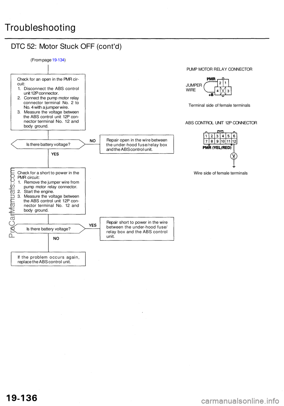
DTC 52 : Moto r Stuc k OF F (cont'd )
(From pag e 19-134 )
Chec k fo r a n ope n in th e PM R cir -
cuit :
1 . Disconnec t th e AB S contro l
unit 12 P connector .2. Connec t th e pum p moto r rela y
connecto r termina l No . 2 to
No . 4 wit h a jumpe r wire .3. Measur e th e voltag e betwee n
th e AB S contro l uni t 12 P con -
necto r termina l No . 1 2 an dbod y ground .
I s ther e batter y voltage ?
Chec k fo r a shor t t o powe r i n th e
PM R circuit :
1 . Remov e th e jumpe r wir e fro m
pum p moto r rela y connector .
2 . Star t th e engine .
3 . Measur e th e voltag e betwee n
th e AB S contro l uni t 12 P con -
necto r termina l No . 1 2 an d
bod y ground . Repai
r ope n in th e wir e betwee n
th e under-hoo d fuse/rela y bo x
and th e AB S contro l unit .
Wire sid e o f femal e terminal s
I s ther e batter y voltage ? Repai
r shor t t o powe r i n th e wir e
betwee n th e under-hoo d fuse /
rela y bo x an d th e AB S contro l
unit.
If th e proble m occur s again ,
replac e th e AB S contro l unit .
PUM P MOTO R RELA Y CONNECTO R
JUMPERWIRE
Termina l sid e o f femal e terminal s
AB S CONTRO L UNI T 12 P CONNECTO R
ProCarManuals.com
Page 1186 of 1954
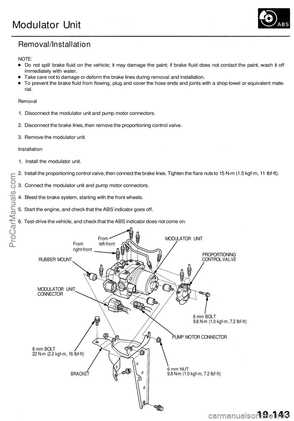
Modulator Unit
Removal/Installation
NOTE:
Do not spill brake fluid on the vehicle; it may damage the paint; if brake fluid does not contact the paint, wash it off
immediately with water.
Take care not to damage or deform the brake lines during removal and installation.
To prevent the brake fluid from flowing, plug and cover the hose ends and joints with a shop towel or equivalent mate-
rial.
Removal
1. Disconnect the modulator unit and pump motor connectors.
2. Disconnect the brake lines, then remove the proportioning control valve.
3. Remove the modulator unit.
Installation
1. Install the modulator unit.
2. Install the proportioning control valve, then connect the brake lines. Tighten the flare nuts to 15 N-m (1.5 kgf-m, 11 Ibf-ft).
3. Connect the modulator unit and pump motor connectors.
4. Bleed the brake system, starting with the front wheels.
5. Start the engine, and check that the ABS indicator goes off.
6. Test-drive the vehicle, and check that the ABS indicator does not come on.
From
From left-front
right-front
MODULATOR UNIT
RUBBER MOUNT
MODULATOR UNIT
CONNECTOR
8 mm BOLT
22 N-m (2.2 kgf-m, 16 Ibf-ft)
BRACKET
PROPORTIONING
CONTROL VALVE
6 mm BOLT
9.8 N-m (1.0 kgf-m, 7.2 Ibf-ft)
PUMP MOTOR CONNECTOR
6 mm NUT
9.8 N-m (1.0 kgf-m, 7.2 Ibf-ft)ProCarManuals.com
Page 1191 of 1954
System Description
Outline
Role of System
The traction control is a variable system designed to enhance traction during acceleration and cornering. It does so by
determining the optimum amount of wheel spin for any given driving situation, then suppressing surplus engine power
accordingly.
Construction and Function
The TCS control unit gets signals about the vehicle's speed, direction, and road conditions from sensors at the wheels and
the steering column. Based on these signals, the control unit will determine the optimum amount of wheel spin. Because
the system is variable, the control unit may determine, depending on the driving conditions, that some wheel spin is bene-
ficial (thus enhancing straight-line acceleration), or that no wheel spin is beneficial (thus enhancing cornering). For any
given driving situation, the control unit will determine the amount of wheel spin best suited to the driver's needs and, if
necessary, will then signal the TCS control valve actuator and Powertrain Control Module (PCM) to reduce engine power.
The system is automatically "ready" whenever the engine is started, but can be manually canceled with the TCS switch.
However, once activated, the system cannot be canceled until it is once again in the ready state.
Components:
Wheel sensors: The TCS "shares" the wheel sensors with the ABS. The wheel sensors transmit wheel speed signals to
the TCS through the ABS control unit.
Steering angle sensor: The steering angle sensor signals the TCS control unit about the amount of steering angle.
TCS control valve sensor: The TCS control valve sensor signals the TCS control unit about the amount of TCS control
valve angle.
TCS control valve actuator: The actuator gets signals from the TCS control unit and closes the TCS control valve
accordingly.
TCS control unit: The TCS control unit detects the driving condition signals from the sensors and, if necessary, signals
the Powertrain Control Module (PCM).ProCarManuals.com
Page 1192 of 1954
Construction and Function
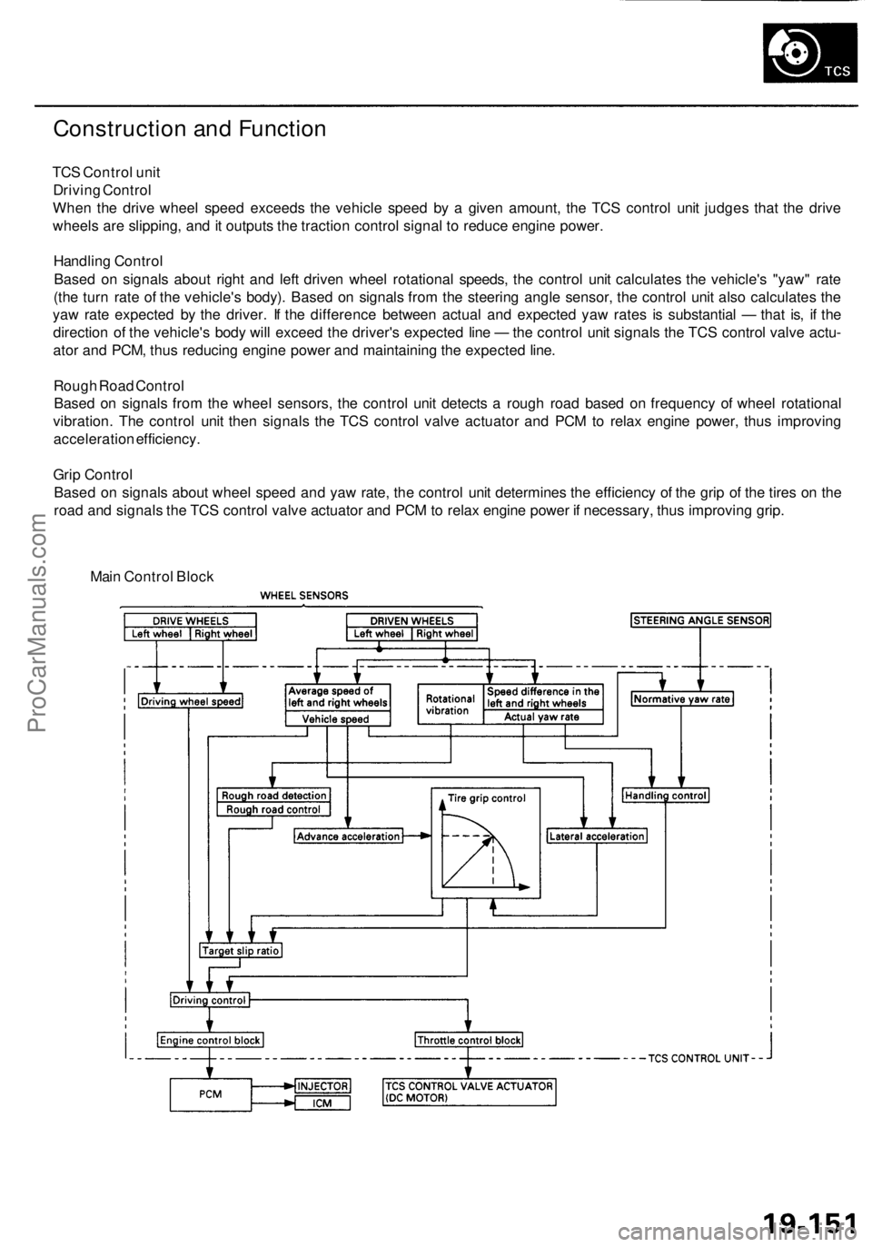
TCS Control unit
Driving Control
When the drive wheel speed exceeds the vehicle speed by a given amount, the TCS control unit judges that the drive
wheels are slipping, and it outputs the traction control signal to reduce engine power.
Handling Control
Based on signals about right and left driven wheel rotational speeds, the control unit calculates the vehicle's "yaw" rate
(the turn rate of the vehicle's body). Based on signals from the steering angle sensor, the control unit also calculates the
yaw rate expected by the driver. If the difference between actual and expected yaw rates is substantial — that is, if the
direction of the vehicle's body will exceed the driver's expected line — the control unit signals the TCS control valve actu-
ator and PCM, thus reducing engine power and maintaining the expected line.
Rough Road Control
Based on signals from the wheel sensors, the control unit detects a rough road based on frequency of wheel rotational
vibration. The control unit then signals the TCS control valve actuator and PCM to relax engine power, thus improving
acceleration efficiency.
Grip Control
Based on signals about wheel speed and yaw rate, the control unit determines the efficiency of the grip of the tires on the
road and signals the TCS control valve actuator and PCM to relax engine power if necessary, thus improving grip.
Main Control BlockProCarManuals.com
Page 1194 of 1954
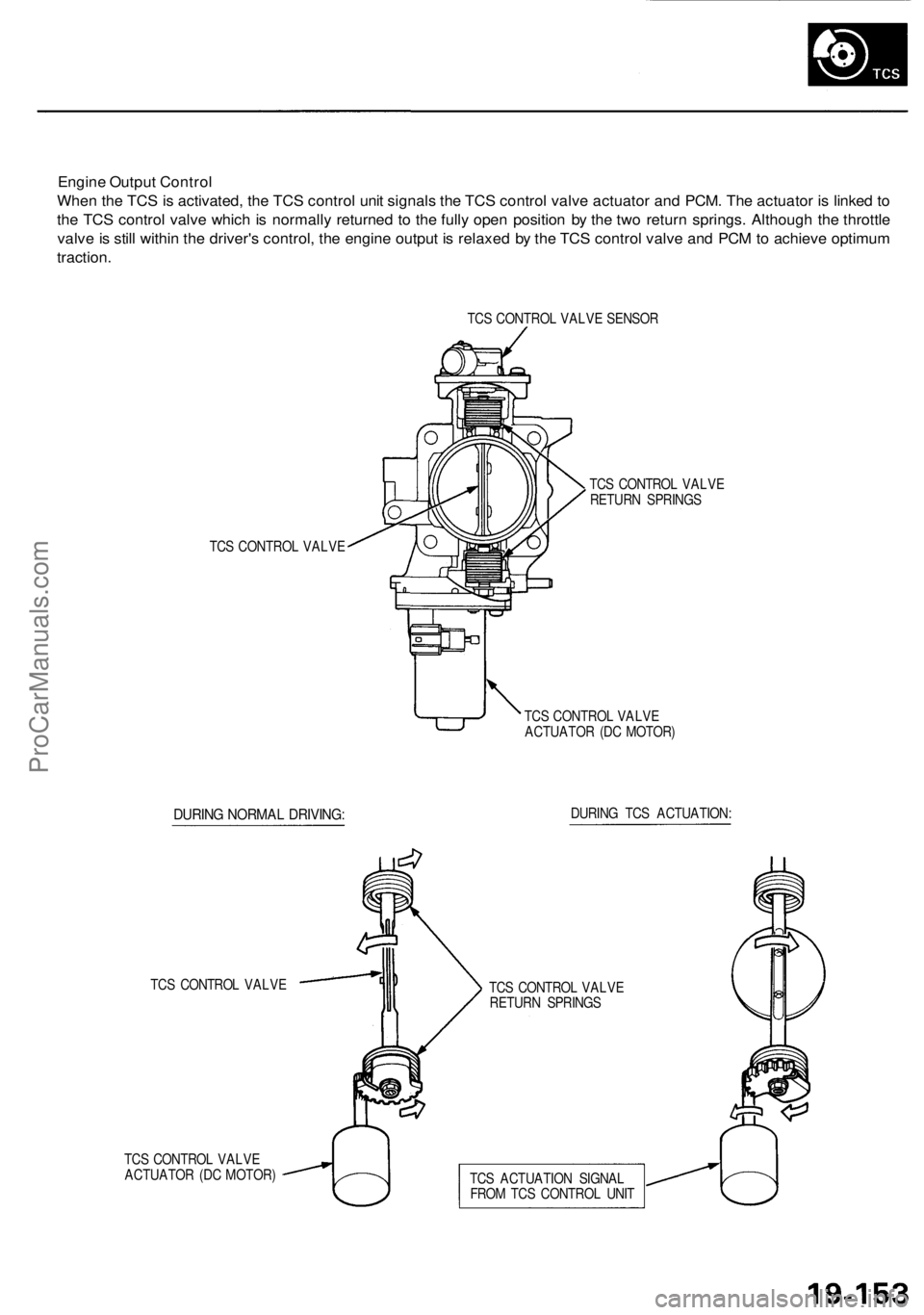
Engine Output Control
When the TCS is activated, the TCS control unit signals the TCS control valve actuator and PCM. The actuator is linked to
the TCS control valve which is normally returned to the fully open position by the two return springs. Although the throttle
valve is still within the driver's control, the engine output is relaxed by the TCS control valve and PCM to achieve optimum
traction.
TCS CONTROL VALVE SENSOR
TCS CONTROL VALVE
TCS CONTROL VALVE
RETURN SPRINGS
TCS CONTROL VALVE
ACTUATOR (DC MOTOR)
DURING NORMAL DRIVING:
DURING TCS ACTUATION:
TCS CONTROL VALVE
TCS CONTROL VALVE
ACTUATOR (DC MOTOR)
TCS CONTROL VALVE
RETURN SPRINGS
TCS ACTUATION SIGNAL
FROM TCS CONTROL UNITProCarManuals.com
Page 1196 of 1954

TCS CONTROL UNIT 20P CONNECTOR
Wire side of female terminals
VB: Battery Voltage
Terminal
number
1
2
4
5
6
9
10
11
12
13
14
15
16
17
20
Wire
color
BLK/YEL
GRN/RED
BLU
PNK/BLU
BLK/WHT
BLK
BRN/WHT
GRN/WHT
BLU
GRN/ORN
BLK/ORN
BRN/BLK
WHT/BLU
BLU/GRY
GRN
BRN
Terminal sign
(Terminal name)
IG1
(Ignition 1)
PARK
(Parking)
SCS
(Service check
signal)
STR-GND
(Steering ground)
AT-SHIFT
(AT shift)
FSR
(Fail-safe relay)
PMG
(Power motor
Ground)
VPM
(Voltage power
motor)
STOP
(Stop)
NEP (Engine
speed pulse)
BARO
(Barometric)
TC-FC
(Traction control
fuel cut)
LG2
(Logic ground 2)
STR-VCC (Steer-
ing power supply)
WARN2
(Warning 2)
SH-MOT
(Shield motor)
MOT +
(Motor +)
MOT-
(Motor -)
Description
Detects ignition switch
IG1 signal
Detects parking brake
switch signal
Detects service check
connector signal
(Diagnostic trouble
code indication)
Ground for the steering
angle sensor
Detects A/T shift posi-
tion signal
Drives fail-safe relay
Power ground for the
TCS control valve
actuator motor
Power source for the
TCS control valve
actuator motor
Detects brake pedal
position switch signal
Detects engine speed
signal
Detects barometric
sensor signal
TCS Fl, Fuel cut
(torque down) signal
Ground for the logic
circuit
Power source for the
steering angle sensor
Drives TCS indicator light
(The indicator light comes
on by the self-bias)
Shield for the TCS con-
trol valve actuator motor
Drives TCS control
valve actuator motor
Drives TCS control
valve actuator motor
Measurement
terminals
1-GND
2
3-GND
4-GND
5-GND
6-GND
9-GND
10-GND
11-GND
12-GND
13-GND
14-GND
15-GND
16-GND
17-GND
19-20
20-19
Voltage
Conditions
(Ignition Switch ON (II))
Depress the parking
brake pedal.
Release the parking
brake pedal.
SCS service connector
connected.
SCS service connector
disconnected.
Shift the transmission
to position, then
start the engine.
Start the engine.
Start the engine.
Brake pedal depressed.
Brake pedal released.
Engine idling
TCS is functioning,
(maximum fuel cut)
TCS is not functioning.
Indicator light ON
Indicator light OFF
TCS is functioning.
TCS is not functioning.
TCS is functioning.
TCS is not functioning.
Output
voltage
VB
Below 0.6 V
VB
0V
5V
Below 0.3V
About 4V
(5V 0V)
VB
1.5V
Below 0.3 V
0V
VB
VB
0V
About 6V
(12V
0V)
About 3 V
About 1.5V
About 4.5 V
(5 V,
PWM)
Below 0.3V
About 5 V
About 2 V
VB
VB
0V
VB
0VProCarManuals.com