engine ACURA RL KA9 1996 Service Repair Manual
[x] Cancel search | Manufacturer: ACURA, Model Year: 1996, Model line: RL KA9, Model: ACURA RL KA9 1996Pages: 1954, PDF Size: 61.44 MB
Page 1510 of 1954
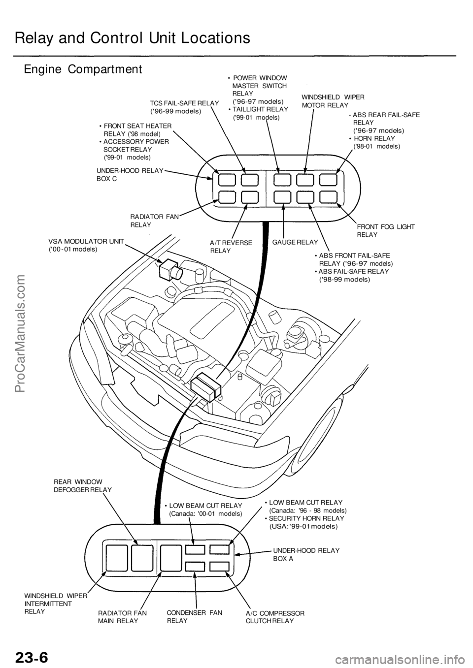
Relay an d Contro l Uni t Location s
Engine Compartmen t
TCS FAIL-SAF E RELA Y('96-99 models )
• FRON T SEA T HEATE R
RELA Y ('9 8 model )
• ACCESSOR Y POWE R
SOCKE T RELA Y
('9 9-0 1 models )
UNDER-HOO D RELA Y
BOX C
RADIATO R FA NRELA Y
VSA MODULATO R UNI T('00 - 01 models )
• POWE R WINDO W
MASTE R SWITC H
RELAY('96-9 7 models )• TAILLIGH T RELA Y
('9 9-0 1 models )WINDSHIEL
D WIPE R
MOTO R RELA Y
- AB S REA R FAIL-SAF E
RELAY('96-9 7 models )• HOR N RELA Y
('9 8-0 1 models )
FRON T FO G LIGH T
RELA Y
• AB S FRON T FAIL-SAF E
RELA Y ('96-9 7 models )
• AB S FAIL-SAF E RELA Y
('98-99 models )
GAUGE RELA Y
A/ T REVERS ERELAY
REAR WINDO W
DEFOGGE R RELA Y
WINDSHIEL D WIPE R
INTERMITTEN TRELAYRADIATO R FA N
MAI N RELA Y CONDENSE
R FA NRELA YA/C COMPRESSO R
CLUTC H RELA Y
•
LO W BEA M CU T RELA Y
(Canada : '9 6 - 9 8 models )
• SECURIT Y HOR N RELA Y
(USA: '99-0 1 models )
• LO W BEA M CU T RELA Y
(Canada : '0 0-0 1 models )
UNDER-HOO D RELA Y
BOX A
ProCarManuals.com
Page 1593 of 1954
Description
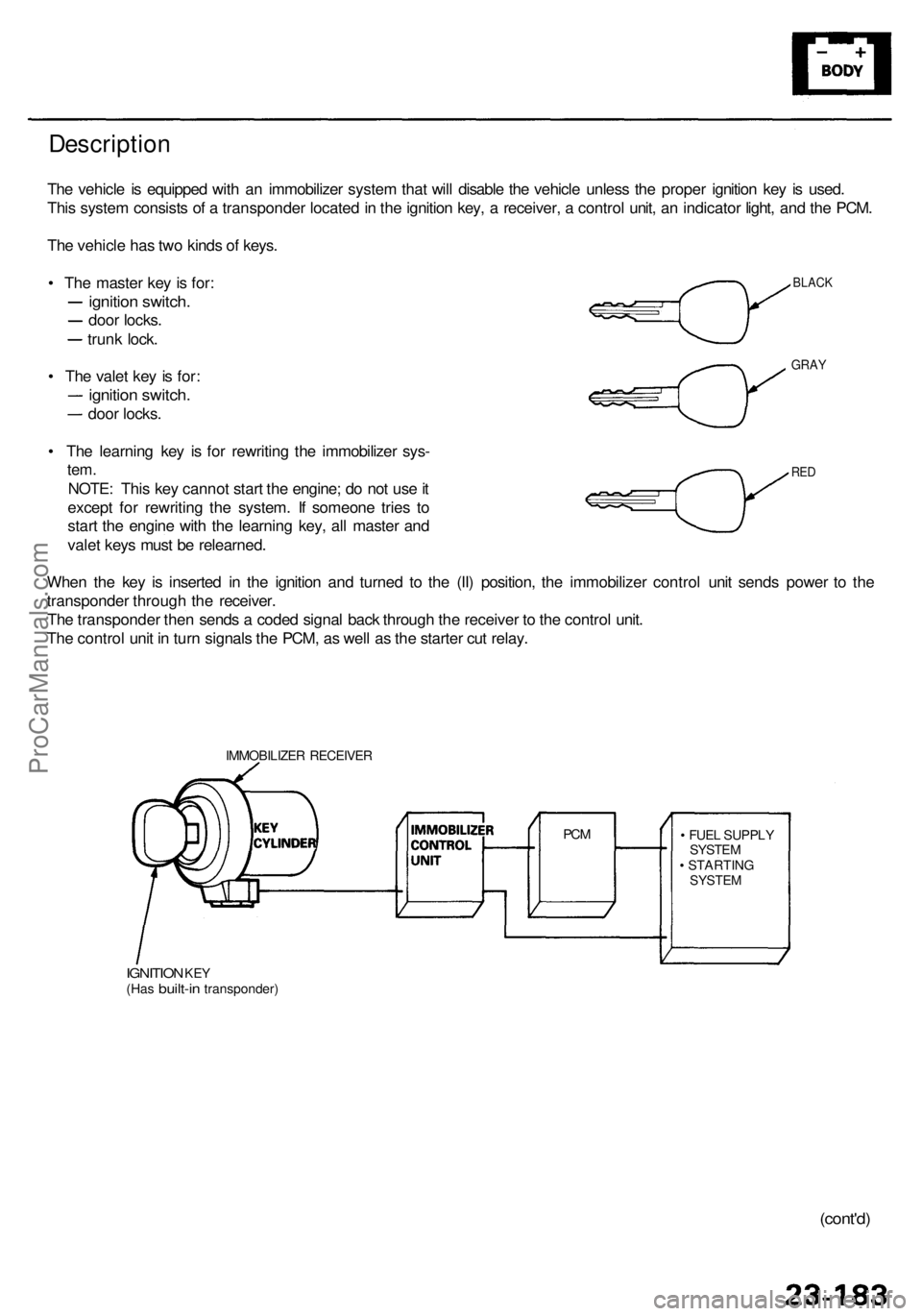
The vehicl e is equippe d wit h a n immobilize r syste m tha t wil l disabl e th e vehicl e unles s th e prope r ignitio n ke y i s used .
Thi s syste m consist s o f a transponde r locate d in th e ignitio n key , a receiver , a contro l unit , a n indicato r light , an d th e PCM .
Th e vehicl e ha s tw o kind s o f keys .
• Th e maste r ke y i s for :
ignitio n switch .
door locks .
trunk lock .
• Th e vale t ke y i s for :
ignitio n switch .
door locks .
• Th e learnin g ke y i s fo r rewritin g th e immobilize r sys -
tem.
NOTE : Thi s ke y canno t star t th e engine ; d o no t us e it
excep t fo r rewritin g th e system . I f someon e trie s t o
star t th e engin e wit h th e learnin g key , al l maste r an d
vale t key s mus t b e relearned .
Whe n th e ke y i s inserte d i n th e ignitio n an d turne d t o th e (II ) position , th e immobilize r contro l uni t send s powe r t o th e
transponde r throug h th e receiver .
Th e transponde r the n send s a code d signa l bac k throug h th e receive r t o th e contro l unit .
Th e contro l uni t i n tur n signal s th e PCM , a s wel l a s th e starte r cu t relay .
IMMOBILIZE R RECEIVE R
IGNITION KEY(Ha s built-i n transponder ) •
FUE L SUPPL Y
SYSTE M
• STARTIN G
SYSTEM
PCM
BLAC K
GRAY
RED
(cont'd )
ProCarManuals.com
Page 1595 of 1954
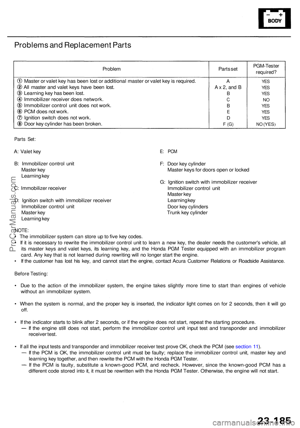
Problems an d Replacemen t Part s
Proble m
Master o r vale t ke y ha s bee n los t o r additiona l maste r o r vale t ke y is required .
Al l maste r an d vale t key s hav e bee n lost .
Learnin g ke y ha s bee n lost .
Immobilize r receive r doe s network .
Immobilize r contro l uni t doe s no t work .
PC M doe s no t work .
Ignitio n switc h doe s no t work .
Doo r ke y cylinde r ha s bee n broken . Part
s se t
PGM-Teste r
required?
YES
YES
YE S
NO
YE S
YE S
YES
NO (YES )
A
A x 2 , an d B
B
C
B
E
D
F (G )
Part s Set :
A: Vale t ke y
B : Immobilize r contro l uni t
Maste r ke y
Learnin g ke y
C : Immobilize r receive r
D : Ignitio n switc h wit h immobilize r receive r
Immobilize r contro l uni t
Maste r ke y
Learnin g ke yE: PC M
F: Doo r ke y cylinde r
Maste r key s fo r door s ope n o r locke d
G : Ignitio n switc h wit h immobilize r receive r
Immobilize r contro l uni t
Maste r ke y
Learnin g ke y
Doo r ke y cylinder s
Trun k ke y cylinde r
NOTE:
• Th e immobilize r syste m ca n stor e u p to fiv e ke y codes .
• I f i t i s necessar y t o rewrit e th e immobilize r contro l uni t t o lear n a ne w key , th e deale r need s th e customer' s vehicle , al l
it s maste r key s an d vale t keys , it s learnin g key , an d th e Hond a PG M Teste r equippe d wit h a n immobilize r progra m
card . An y ke y tha t i s no t learne d durin g rewritin g wil l n o longe r star t th e engine .
• I f th e custome r ha s los t hi s key , an d canno t star t th e engine , contac t Acur a Custome r Relation s o r Roadsid e Assistance .
Before Testing :
• Du e t o th e actio n o f th e immobilize r system , th e engin e take s slightl y mor e tim e t o star t tha n engine s o f vehicl e
withou t a n immobilize r system .
• Whe n th e syste m is normal , an d th e prope r ke y i s inserted , th e indicato r ligh t come s o n fo r 2 seconds , the n i t wil l g o
off .
• I f th e indicato r start s t o blin k afte r 2 seconds , o r i f th e engin e doe s no t start , repea t th e startin g procedure .
If th e engin e stil l doe s no t start , perfor m th e immobilize r contro l uni t inpu t tes t an d transponde r an d immobilize r
receive r test .
• I f al l th e inpu t test s an d transponde r an d immobilize r receive r tes t prov e OK , chec k th e PC M (se e sectio n 11 ).
I f th e PC M is OK , th e immobilize r contro l uni t mus t b e faulty ; replac e th e immobilize r contro l unit , maste r ke y an d
learnin g ke y together , an d the n rewrit e th e PC M wit h th e Hond a PG M Tester .
If th e PC M is faulty , substitut e a known-goo d PCM , an d recheck . However , sinc e th e known-goo d PC M ha s a
differen t cod e store d int o it , i t mus t b e rewritte n wit h th e Hond a PG M Tester . Otherwise , th e engin e wil l no t start .
ProCarManuals.com
Page 1810 of 1954
To UNDER-DASH
FUSE/RELAY BOX
2P CONNECTOR
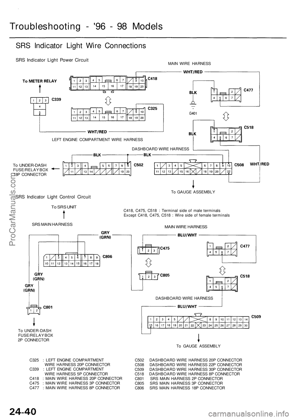
Troubleshooting - '96 - 98 Models
SRS Indicator Light Wire Connections
SRS Indicator Light Power Circuit
MAIN WIRE HARNESS
LEFT ENGINE COMPARTMENT WIRE HARNESS
To UNDER-DASH
FUSE/RELAY BOX
18P CONNECTOR
SRS Indicator Light Control Circuit
To SRS UNIT
SRS MAIN HARNESS
C418, C475, C518 : Terminal side of male terminals
Except C418, C475, C518 : Wire side of female terminals
MAIN WIRE HARNESS
To GAUGE ASSEMBLY
DASHBOARD WIRE HARNESS
DASHBOARD WIRE HARNESS
To GAUGE ASSEMBLY
C325 : LEFT ENGINE COMPARTMENT
WIRE HARNESS 20P CONNECTOR
C339 : LEFT ENGINE COMPARTMENT
WIRE HARNESS 5P CONNECTOR
C418 : MAIN WIRE HARNESS 20P CONNECTOR
C475 : MAIN WIRE HARNESS 3P CONNECTOR
C477 : MAIN WIRE HARNESS 8P CONNECTOR
C502 DASHBOARD WIRE HARNESS 20P CONNECTOR
C508 DASHBOARD WIRE HARNESS 22P CONNECTOR
C509 DASHBOARD WIRE HARNESS 30P CONNECTOR
C518 DASHBOARD WIRE HARNESS 8P CONNECTOR
C801 SRS MAIN HARNESS 2P CONNECTOR
C805 SRS MAIN HARNESS 3P CONNECTOR
C806 SRS MAIN HARNESS 18P CONNECTORProCarManuals.com
Page 1858 of 1954
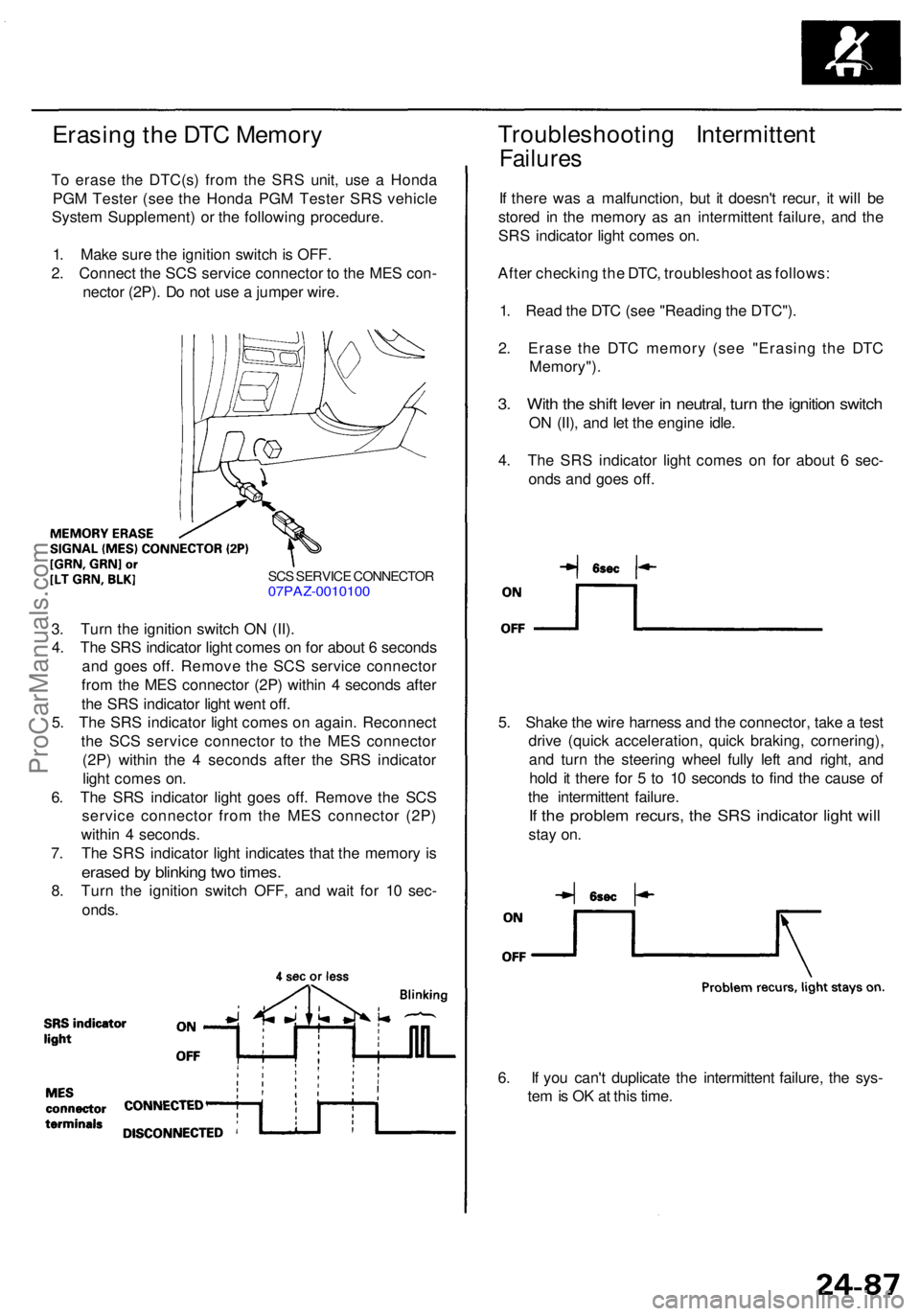
Erasing th e DT C Memor y
To eras e th e DTC(s ) fro m th e SR S unit , us e a Hond a
PG M Teste r (se e th e Hond a PG M Teste r SR S vehicl e
Syste m Supplement ) o r th e followin g procedure .
1 . Mak e sur e th e ignitio n switc h is OFF .
2 . Connec t th e SC S servic e connecto r t o th e ME S con -
necto r (2P) . D o no t us e a jumpe r wire .
Troubleshootin g Intermitten t
Failures
If ther e wa s a malfunction , bu t i t doesn' t recur , i t wil l b e
store d i n th e memor y a s a n intermitten t failure , an d th e
SR S indicato r ligh t come s on .
Afte r checkin g th e DTC , troubleshoo t a s follows :
1 . Rea d th e DT C (se e "Readin g th e DTC") .
2 . Eras e th e DT C memor y (se e "Erasin g th e DT C
Memory") .
3. Wit h th e shif t leve r i n neutral , tur n th e ignitio n switc h
ON (II) , an d le t th e engine idle.
4 . Th e SR S indicato r ligh t come s o n fo r abou t 6 sec -
ond s an d goe s off .
SCS SERVIC E CONNECTO R07PAZ-001010 0
3. Tur n th e ignitio n switc h O N (II) .
4 . Th e SR S indicato r ligh t come s o n fo r abou t 6 second s
an d goe s off . Remov e th e SC S servic e connecto r
fro m th e ME S connecto r (2P ) withi n 4 second s afte r
th e SR S indicato r ligh t wen t off .
5 . Th e SR S indicato r ligh t come s o n again . Reconnec t
th e SC S servic e connecto r t o th e ME S connecto r
(2P ) withi n th e 4 second s afte r th e SR S indicato r
ligh t come s on .
6 . Th e SR S indicato r ligh t goe s off . Remov e th e SC S
servic e connecto r fro m th e ME S connecto r (2P )
withi n 4 seconds .
7 . Th e SR S indicato r ligh t indicate s tha t th e memor y i s
erase d b y blinkin g tw o times .
8. Tur n th e ignitio n switc h OFF , an d wai t fo r 1 0 sec -
onds . 5
. Shak e th e wir e harnes s an d th e connector , tak e a tes t
driv e (quic k acceleration , quic k braking , cornering) ,
an d tur n th e steerin g whee l full y lef t an d right , an d
hol d i t ther e fo r 5 to 1 0 second s t o fin d th e caus e o f
th e intermitten t failure .
If th e proble m recurs , th e SR S indicato r ligh t wil l
stay on .
6 . I f yo u can' t duplicat e th e intermitten t failure , th e sys -
te m is O K a t thi s time .
ProCarManuals.com
Page 1859 of 1954
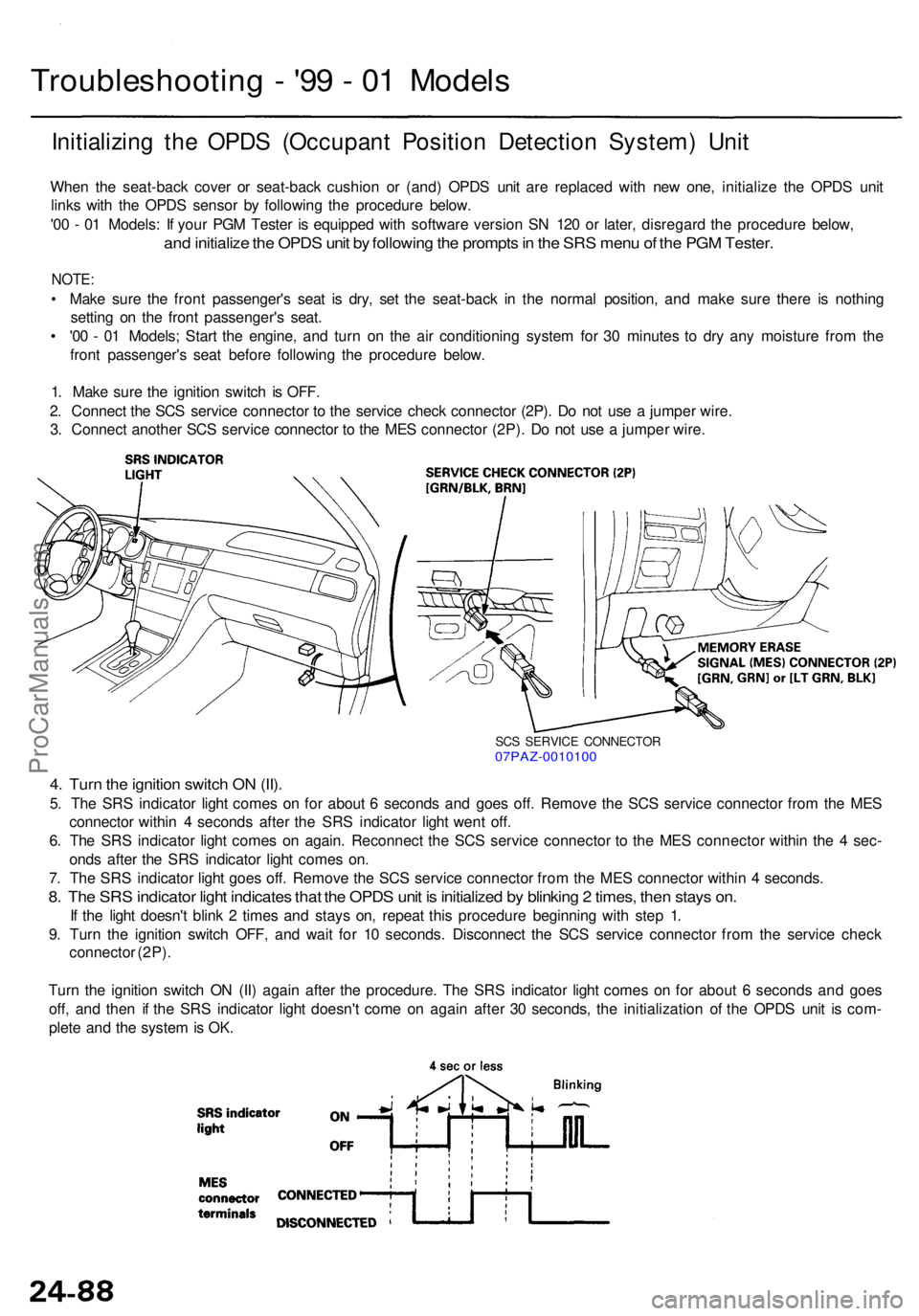
Troubleshooting - '9 9 - 0 1 Model s
Initializin g th e OPD S (Occupan t Positio n Detectio n System ) Uni t
Whe n th e seat-bac k cove r o r seat-bac k cushio n o r (and ) OPD S uni t ar e replace d wit h ne w one , initializ e th e OPD S uni t
link s wit h th e OPD S senso r b y followin g th e procedur e below .
'0 0 - 0 1 Models : I f you r PG M Teste r i s equippe d wit h softwar e versio n S N 12 0 o r later , disregar d th e procedur e below ,
and initializ e th e OPD S uni t b y followin g th e prompt s in th e SR S men u o f th e PG M Tester .
NOTE:
• Mak e sur e th e fron t passenger' s sea t i s dry , se t th e seat-bac k i n th e norma l position , an d mak e sur e ther e i s nothin g
settin g o n th e fron t passenger' s seat .
• '0 0 - 0 1 Models ; Star t th e engine , an d tur n o n th e ai r conditionin g syste m fo r 3 0 minute s t o dr y an y moistur e fro m th e
fron t passenger' s sea t befor e followin g th e procedur e below .
1 . Mak e sur e th e ignitio n switc h i s OFF .
2 . Connec t th e SC S servic e connecto r t o th e servic e chec k connecto r (2P) . D o no t us e a jumpe r wire .
3 . Connec t anothe r SC S servic e connecto r t o th e ME S connecto r (2P) . D o no t us e a jumpe r wire .
SCS SERVIC E CONNECTO R07PAZ-001010 0
4. Tur n th e ignitio n switc h O N (II) .
5. Th e SR S indicato r ligh t come s o n fo r abou t 6 second s an d goe s off . Remov e th e SC S servic e connecto r fro m th e ME S
connecto r withi n 4 second s afte r th e SR S indicato r ligh t wen t off .
6 . Th e SR S indicato r ligh t come s o n again . Reconnec t th e SC S servic e connecto r t o th e ME S connecto r withi n th e 4 sec -
ond s afte r th e SR S indicato r ligh t come s on .
7 . Th e SR S indicato r ligh t goe s off . Remov e th e SC S servic e connecto r fro m th e ME S connecto r withi n 4 seconds .
8. Th e SR S indicato r ligh t indicate s tha t th e OPD S uni t i s initialize d b y blinkin g 2 times , the n stay s on .
If th e ligh t doesn' t blin k 2 time s an d stay s on , repea t thi s procedur e beginnin g wit h ste p 1 .
9 . Tur n th e ignitio n switc h OFF , an d wai t fo r 1 0 seconds . Disconnec t th e SC S servic e connecto r fro m th e servic e chec k
connecto r (2P) .
Tur n th e ignitio n switc h O N (II ) agai n afte r th e procedure . Th e SR S indicato r ligh t come s o n fo r abou t 6 second s an d goe s
off , an d the n i f th e SR S indicato r ligh t doesn' t com e o n agai n afte r 3 0 seconds , th e initializatio n o f th e OPD S uni t i s com -
plet e an d th e syste m is OK .
ProCarManuals.com
Page 1864 of 1954
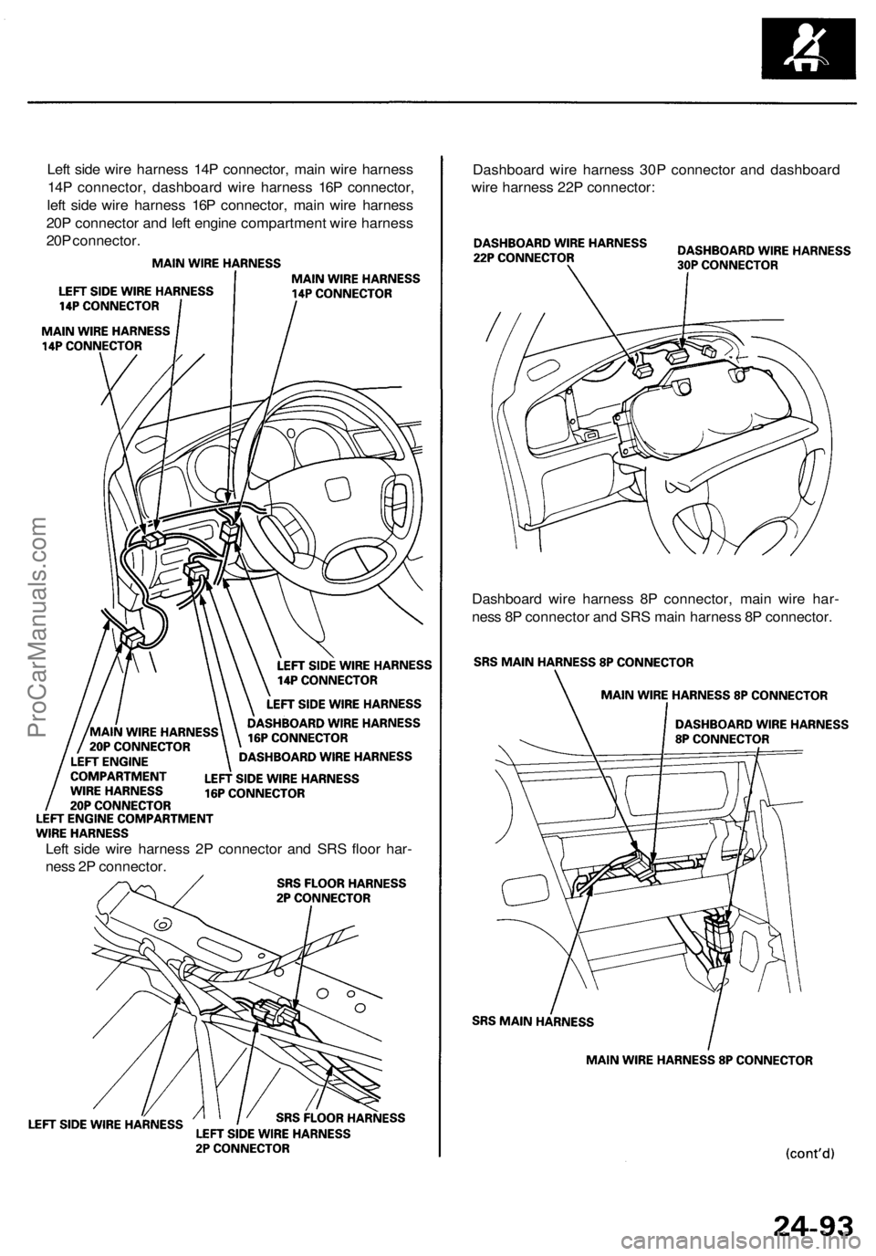
Left side wire harness 14P connector, main wire harness
14P connector, dashboard wire harness 16P connector,
left side wire harness 16P connector, main wire harness
20P connector and left engine compartment wire harness
20P connector.
Dashboard wire harness 30P connector and dashboard
wire harness 22P connector:
Dashboard wire harness 8P connector, main wire har-
ness 8P connector and SRS main harness 8P connector.
Left side wire harness 2P connector and SRS floor har-
ness 2P connector.ProCarManuals.com