buttons ACURA RL KA9 1996 Service Owner's Manual
[x] Cancel search | Manufacturer: ACURA, Model Year: 1996, Model line: RL KA9, Model: ACURA RL KA9 1996Pages: 1954, PDF Size: 61.44 MB
Page 632 of 1954
Fuel Suppl y Syste m
System Descriptio n
The fue l suppl y syste m consist s o f a fue l tank , in-tan k
high-pressur e fue l pump , PGM-F I mai n relay , fue l filter ,
fue l pressur e regulator , fue l pressur e regulato r contro l
solenoi d valve , injectors , an d fue l deliver y an d retur n
lines . Thi s syste m deliver s pressure-regulate d fue l t o th e
injector s an d cut s th e fue l deliver y whe n th e engin e i s
no t running .
Fuel Pressur e
Relieving
Befor e disconnectin g fue l pipe s o r hoses , releas e pres -
sur e fro m th e syste m b y loosenin g th e servic e bol t o n
top o f th e fue l filter .
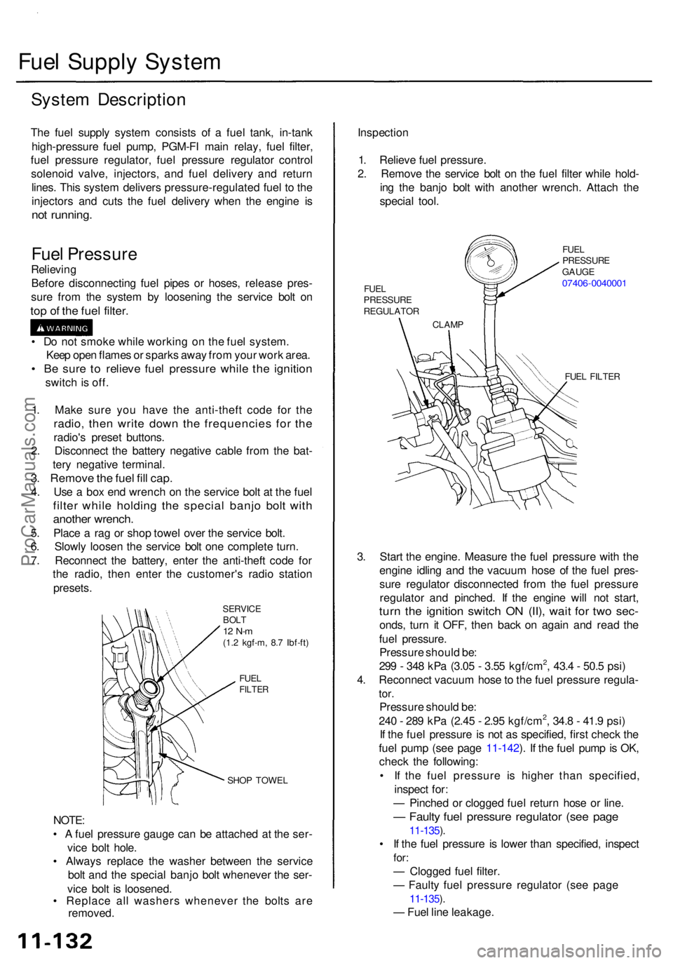
SERVIC E
BOL T
12 N- m(1.2 kgf-m , 8. 7 Ibf-ft )
FUE L
FILTE R
SHOP TOWE L
NOTE:
• A fue l pressur e gaug e can be attache d a t th e ser -
vic e bol t hole .
• Alway s replac e th e washe r betwee n th e servic e
bol t an d th e specia l banj o bol t wheneve r th e ser -
vic e bol t i s loosened .
• Replac e al l washer s wheneve r th e bolt s ar e
removed . Inspectio
n
1 . Reliev e fue l pressure .
2 . Remov e th e servic e bol t o n th e fue l filte r whil e hold -
in g th e banj o bol t wit h anothe r wrench . Attac h th e
specia l tool .
FUEL FILTE R
3. Star t th e engine . Measur e th e fue l pressur e wit h th e
engin e idlin g an d th e vacuu m hos e o f th e fue l pres -
sur e regulato r disconnecte d fro m th e fue l pressur e
regulato r an d pinched . I f th e engin e wil l no t start ,
turn th e ignitio n switc h O N (II) , wai t fo r tw o sec -
onds , tur n i t OFF , the n bac k o n agai n an d rea d th e
fue l pressure .
Pressur e shoul d be :
29 9 - 34 8 kP a (3.0 5 - 3.5 5 kgf/cm
2, 43. 4 - 50. 5 psi )
4 . Reconnec t vacuu m hos e to th e fue l pressur e regula -
tor.
Pressur e shoul d be :
24 0 - 28 9 kP a (2.4 5 - 2.9 5 kgf/cm2, 34. 8 - 41. 9 psi )
I f th e fue l pressur e i s no t a s specified , firs t chec k th e
fue l pum p (se e pag e 11-142 ). I f th e fue l pum p is OK ,
chec k th e following :
• I f th e fue l pressur e i s highe r tha n specified ,
inspec t for :
— Pinche d o r clogge d fue l retur n hos e o r line .
— Fault y fue l pressur e regulato r (se e pag e
11-135 ).
• I f th e fue l pressur e i s lowe r tha n specified , inspec t
for:
— Clogge d fue l filter .
— Fault y fue l pressur e regulato r (se e pag e
11-135 ).
— Fue l lin e leakage .
1
. Mak e sur e yo u hav e th e anti-thef t cod e fo r th e
radio , the n writ e dow n th e frequencie s fo r th e
radio' s prese t buttons .
2 . Disconnec t th e batter y negativ e cabl e fro m th e bat -
ter y negativ e terminal .
3. Remov e th e fue l fil l cap .
4. Us e a bo x en d wrenc h o n th e servic e bol t a t th e fue l
filte r whil e holdin g th e specia l banj o bol t wit h
anothe r wrench .
5. Plac e a ra g o r sho p towe l ove r th e servic e bolt .
6 . Slowl y loose n th e servic e bol t on e complet e turn .
7 . Reconnec t th e battery , ente r th e anti-thef t cod e fo r
th e radio , the n ente r th e customer' s radi o statio n
presets .
•
D o no t smok e whil e workin g o n th e fue l system .
Kee p ope n flame s o r spark s awa y fro m you r wor k area .
• B e sur e t o reliev e fue l pressur e whil e th e ignitio n
switch is off .
CLAM P
FUE
L
PRESSUR E
REGULATO R FUE
L
PRESSUR E
GAUG E
07406-004000 1
ProCarManuals.com
Page 762 of 1954
PCM Rese t Procedur e
1 . Mak e sur e yo u hav e th e anti-thef t cod e fo r th e radio , the n writ e dow n th e frequencie s fo r th e radio' s prese t buttons .
2 . Tur n th e ignitio n switc h OFF .
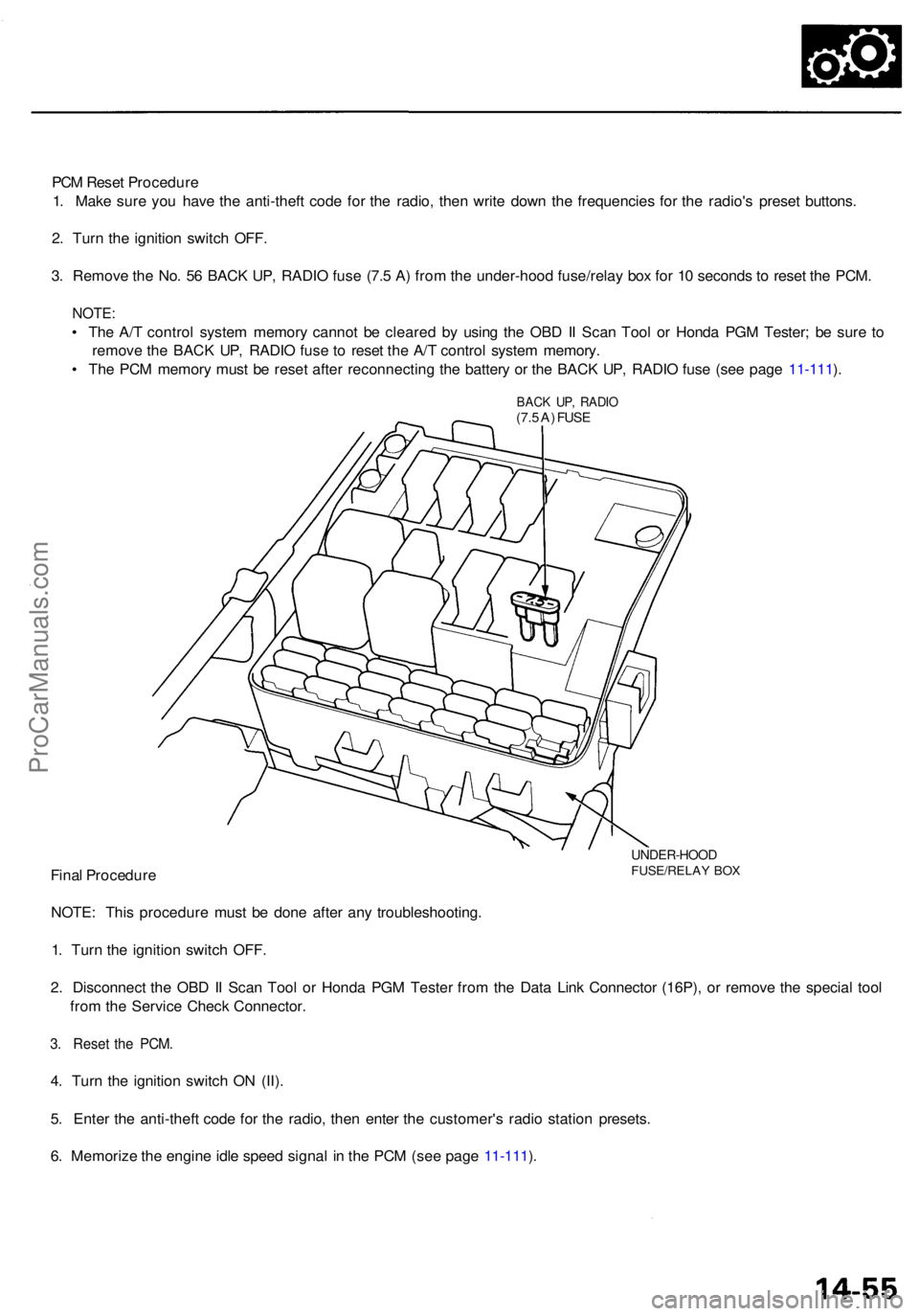
3 . Remov e th e No . 5 6 BAC K UP , RADI O fus e (7. 5 A ) fro m th e under-hoo d fuse/rela y bo x fo r 1 0 second s t o rese t th e PCM .
NOTE :
• Th e A/ T contro l syste m memor y canno t b e cleare d b y usin g th e OB D II Sca n Too l o r Hond a PG M Tester ; b e sur e t o
remov e th e BAC K UP , RADI O fus e t o rese t th e A/ T contro l syste m memory .
• Th e PC M memor y mus t b e rese t afte r reconnectin g th e batter y o r th e BAC K UP , RADI O fus e (se e pag e 11-111 ).
BAC K UP , RADI O(7.5 A ) FUS E
UNDER-HOO DFUSE/RELAY BO XFina l Procedur e
NOTE : Thi s procedur e mus t b e don e afte r an y troubleshooting .
1 . Tur n th e ignitio n switc h OFF .
2 . Disconnec t th e OB D II Sca n Too l o r Hond a PG M Teste r fro m th e Dat a Lin k Connecto r (16P) , o r remov e th e specia l too l
fro m th e Servic e Chec k Connector .
3. Rese t th e PCM .
4. Tur n th e ignitio n switc h O N (II) .
5 . Ente r th e anti-thef t cod e fo r th e radio , the n ente r th e customer' s radi o statio n presets .
6 . Memoriz e th e engin e idl e spee d signa l i n th e PC M (se e pag e 11-111 ).
ProCarManuals.com
Page 823 of 1954
Transmission
Removal
Make sur e lift s ar e place d properl y an d
hois t bracket s ar e attache d t o th e correc t positio n o n
th e engin e (se e sectio n 1 ).
CAUTION : Us e fende r cover s t o avoi d damagin g paint -
ed surfaces .
NOTE: Th e PC M memor y mus t b e rese t afte r reconnectin g
th e batter y o r th e BAC K UP , RADI O fus e (se e pag e 11-125 ).
1 . Befor e yo u disconnec t power , mak e sur e yo u hav e
th e anti-thef t cod e fo r th e radio , the n writ e dow n
the frequencie s fo r th e radio' s prese t buttons .
2. Disconnec t th e batter y negativ e (- ) termina l fro m
th e battery , the n remov e th e positiv e (+ ) terminal .
3. Shif t th e transmissio n int o th e position .
4 . Remov e th e stru t brace .
5 . Remov e th e contro l box .
CAUTION : D o no t remov e th e vacuu m tube s fro m
th e contro l box .
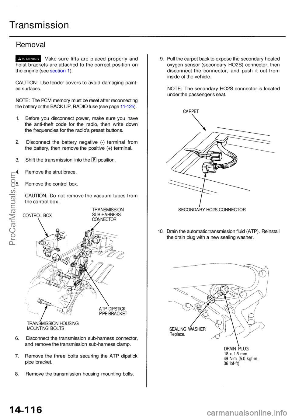
CONTRO L BO X
TRANSMISSIO NSUB-HARNESS
CONNECTO R
AT P DIPSTIC K
PIP E BRACKE T
9. Pul l th e carpe t bac k to expos e th e secondar y heate d
oxyge n senso r (secondar y HO2S ) connector, then
disconnec t th e connector , an d pus h i t ou t fro m
insid e o f th e vehicle .
NOTE : Th e secondar y HO2 S connecto r i s locate d
unde r th e passenger' s seat .
CARPE T
SECONDARY HO2S CONNECTOR
10. Drai n th e automati c transmissio n flui d (ATP) . Reinstal l
th e drai n plu g wit h a ne w sealin g washer .
SEALIN G WASHE R
Replace .
DRAIN PLU G
18 x 1. 5 m m49 N- m (5. 0 kgf-m ,
3 6 Ibf-ft )
6. Disconnec t th e transmissio n sub-harnes s connector ,
an d remov e th e transmissio n sub-harnes s clamp .
7 . Remov e th e thre e bolt s securin g th e AT P dipstic k
pip e bracket .
8 . Remov e th e transmissio n housin g mountin g bolts .
TRANSMISSIO N HOUSIN GMOUNTIN G BOLT S
ProCarManuals.com
Page 1366 of 1954
Climate contro l uni t an d audi o uni t ('9 6 - 9 8 models) :
SR S component s ar e locate d in thi s area . Revie w th e SR S
componen t locations , precautions , an d procedure s i n th e
Restraint s ( sectio n 24 ) befor e performin g repair s o r ser -
vice .
1. Remov e th e consol e pane l (se e pag e 20-48 ).
2 . Remov e th e cente r ai r vent .
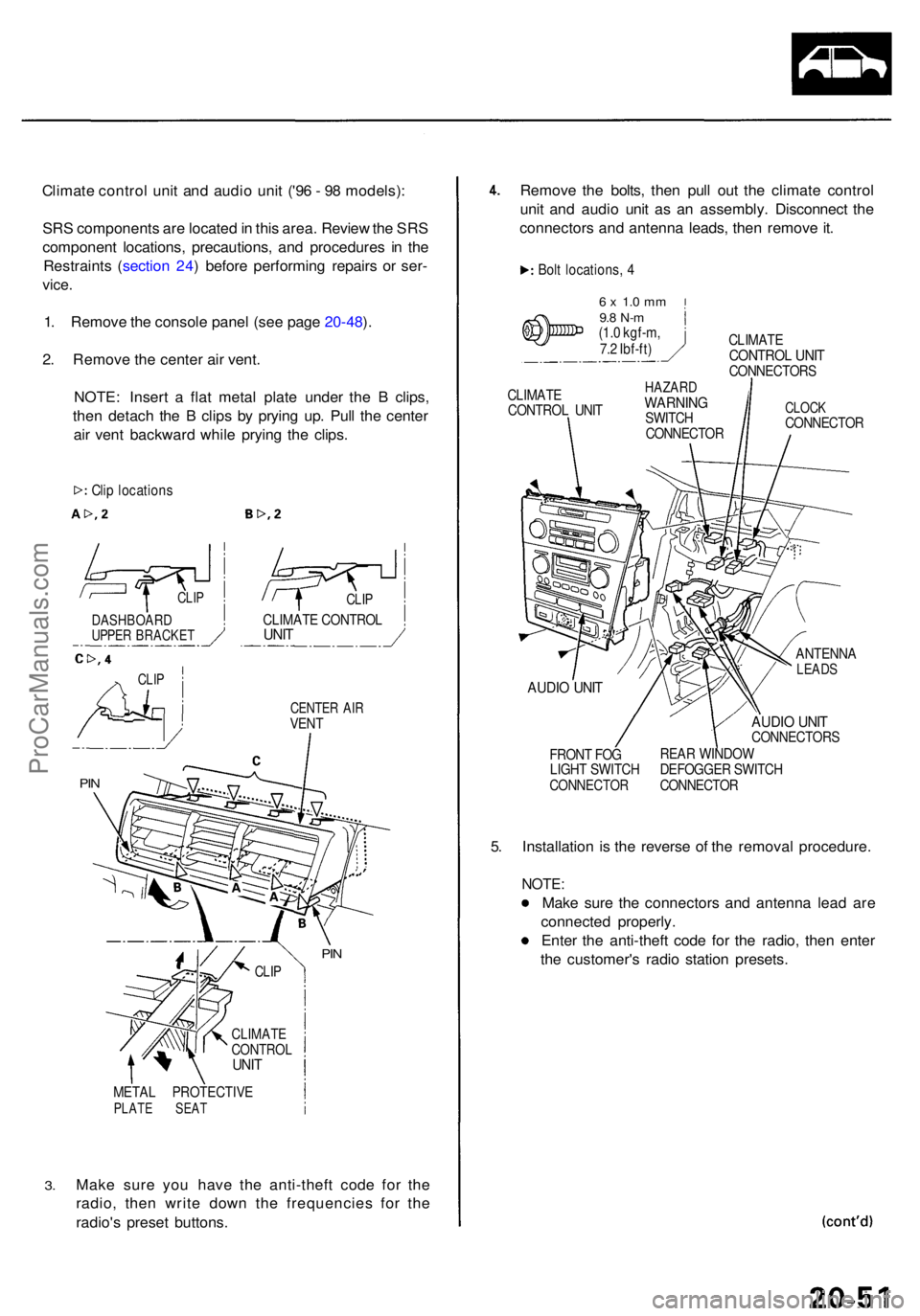
NOTE : Inser t a fla t meta l plat e unde r th e B clips ,
the n detac h th e B clip s b y pryin g up . Pul l th e cente r
ai r ven t backwar d whil e pryin g th e clips .
CENTE R AI RVEN T
3.
META L PROTECTIV EPLATE SEA T
Make sur e yo u hav e th e anti-thef t cod e fo r th e
radio , the n writ e dow n th e frequencie s fo r th e
radio' s prese t buttons. Remov
e th e bolts , the n pul l ou t th e climat e contro l
uni t an d audi o uni t a s a n assembly . Disconnec t th e
connector s an d antenn a leads , the n remov e it .
Bol t locations , 4
6 x 1. 0 m m9.8 N- m(1.0 kgf-m ,
7. 2 Ibf-ft ) CLIMAT
E
CONTRO L UNI TCONNECTOR S
CLIMAT E
CONTRO L UNI THAZAR DWARNIN GSWITCH
CONNECTO RCLOCKCONNECTO R
AUDIO UNI T
FRON T FO G
LIGH T SWITC H
CONNECTO R
ANTENNALEADS
AUDIO UNI TCONNECTOR S
REA R WINDO W
DEFOGGE R SWITC H
CONNECTO R
5. Installatio n i s th e revers e o f th e remova l procedure .
NOTE:
Make sur e th e connector s an d antenn a lea d ar e
connecte d properly .
Ente r th e anti-thef t cod e fo r th e radio , the n ente r
th e customer' s radi o statio n presets .
Clip location s
CLIPCLIP
CLIMAT E CONTRO LUNITDASHBOAR DUPPER BRACKE T
CLIP
PIN
PIN
CLI P
CLIMAT ECONTRO LUNIT
ProCarManuals.com
Page 1367 of 1954
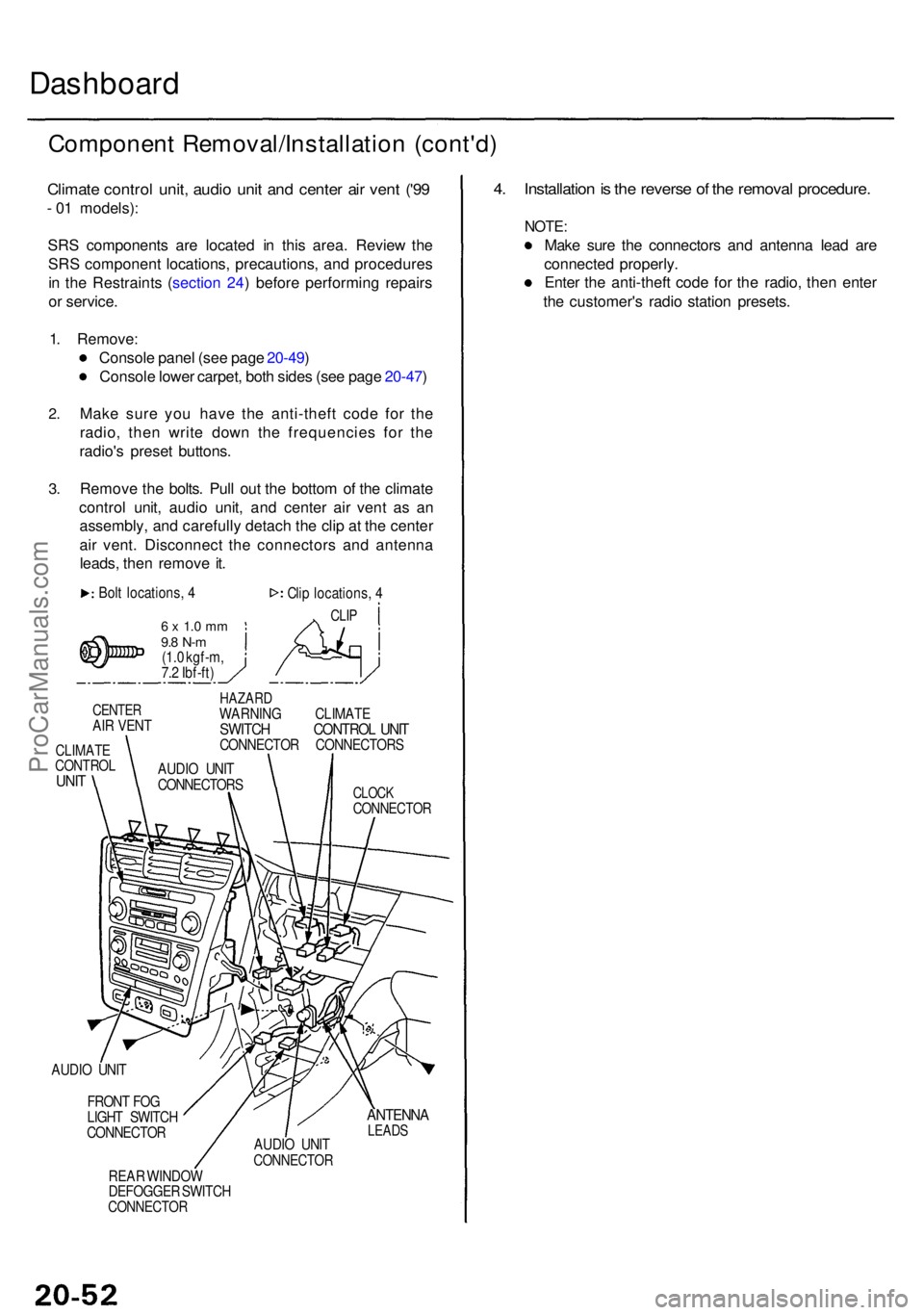
Dashboard
Componen t Removal/Installatio n (cont'd )
Climate contro l unit , audi o uni t an d cente r ai r ven t ('9 9
- 0 1 models) :
SR S component s ar e locate d i n thi s area . Revie w th e
SR S componen t locations , precautions , an d procedure s
i n th e Restraint s ( sectio n 24 ) befor e performin g repair s
o r service .
1 . Remove :
Consol e pane l (se e pag e 20-49 )
Consol e lowe r carpet , bot h side s (se e pag e 20-47 )
2.
3.
Mak e sur e yo u hav e th e anti-thef t cod e fo r th e
radio , the n writ e dow n th e frequencie s fo r th e
radio' s prese t buttons .
Remov e th e bolts . Pul l ou t th e botto m o f th e climat e
contro l unit , audi o unit , an d cente r ai r ven t a s a n
assembly , an d carefull y detac h th e cli p a t th e cente r
ai r vent . Disconnec t th e connector s an d antenn a
leads , the n remov e it .
Bol t locations , 4
6 x 1. 0 m m9.8 N- m(1.0 kgf-m ,
7. 2 Ibf-ft ) Cli
p locations , 4
CLI P
CENTE RAIR VEN T
CLIMAT ECONTRO LUNIT
HAZAR DWARNIN G CLIMAT ESWITCH CONTRO L UNI TCONNECTO R CONNECTOR S
CLOCKCONNECTO R
AUDIO UNI T
FRON T FO G
LIGH T SWITC H
CONNECTO R
REA R WINDO W
DEFOGGE R SWITC H
CONNECTO R
ANTENNALEADSAUDIO UNI TCONNECTO R
4. Installatio n is th e revers e o f th e remova l procedure .
NOTE:
Make sur e th e connector s an d antenn a lea d ar e
connecte d properly .
Ente r th e anti-thef t cod e fo r th e radio , the n ente r
th e customer' s radi o statio n presets .
AUDIO UNI T
CONNECTOR S
ProCarManuals.com
Page 1370 of 1954
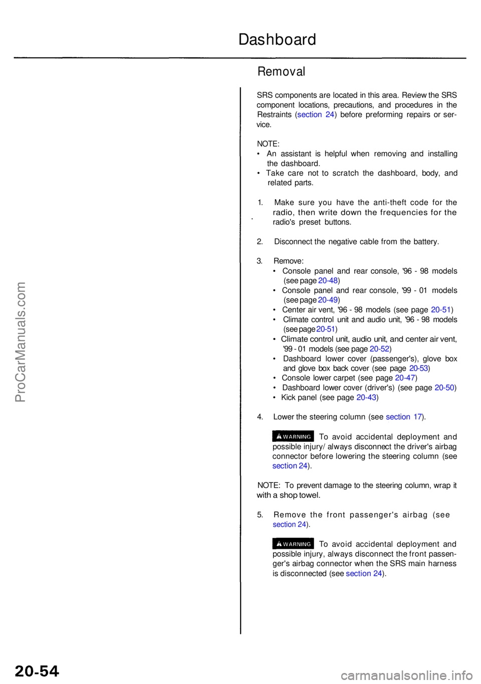
Removal
SRS component s ar e locate d in thi s area . Revie w th e SR S
componen t locations , precautions , an d procedure s i n th e
Restraint s ( sectio n 24 ) befor e preformin g repair s o r ser -
vice .
NOTE :
• A n assistan t i s helpfu l whe n removin g an d installin g
th e dashboard .
• Tak e car e no t t o scratc h th e dashboard , body , an d
relate d parts .
1 . Mak e sur e yo u hav e th e anti-thef t cod e fo r th e
radio , the n writ e dow n th e frequencie s fo r th e
radio' s prese t buttons .
2 . Disconnec t th e negativ e cabl e fro m th e battery .
3 . Remove :
• Consol e pane l an d rea r console , '9 6 - 9 8 model s
(se e pag e 20-48 )
• Consol e pane l an d rea r console , '9 9 - 0 1 model s
(se e pag e 20-49 )
• Cente r ai r vent , '9 6 - 9 8 model s (se e pag e 20-51 )
• Climat e contro l uni t an d audi o unit , '9 6 - 9 8 model s
(se e pag e 20-51 )
• Climat e contro l unit , audi o unit , an d cente r ai r vent ,
'99 - 0 1 model s (se e pag e 20-52 )
• Dashboar d lowe r cove r (passenger's) , glov e bo x
an d glov e bo x bac k cove r (se e pag e 20-53 )
• Consol e lowe r carpe t (se e pag e 20-47 )
• Dashboar d lowe r cove r (driver's ) (se e pag e 20-50 )
• Kic k pane l (se e pag e 20-43 )
4 . Lowe r th e steerin g colum n (se e sectio n 17 ).
T o avoi d accidenta l deploymen t an d
possibl e injury / alway s disconnec t th e driver' s airba g
connecto r befor e lowerin g th e steerin g colum n (se e
sectio n 24 ).
NOTE : T o preven t damag e to th e steerin g column , wra p it
wit h a sho p towel .
5. Remove the front passenger's airbag (see
section 24 ).
T o avoi d accidenta l deploymen t an d
possibl e injury , alway s disconnec t th e fron t passen -
ger' s airba g connecto r whe n th e SR S mai n harnes s
i s disconnecte d (se e sectio n 24 ).
Dashboar d
ProCarManuals.com
Page 1373 of 1954
Front Sea t
Remova l
SRS component s ar e locate d i n thi s area . Revie w th e
SR S componen t locations , precautions , an d procedure s
i n th e Restraint s ( sectio n 24 ) befor e performin g repair s
o r service .
CAUTION : Whe n pryin g wit h a flat-ti p screwdriver , wra p
i t wit h protectiv e tap e t o preven t damage .
NOTE : Tak e car e no t t o scratc h th e sea t cover s an d body .
1 . Mak e sur e yo u hav e th e anti-thef t cod e fo r th e
radio , the n writ e dow n th e frequencie s fo r th e pre -
set buttons .
2. Disconnec t th e negativ e batter y cable , an d wai t a t
leas t 3 minute s befor e beginnin g work .
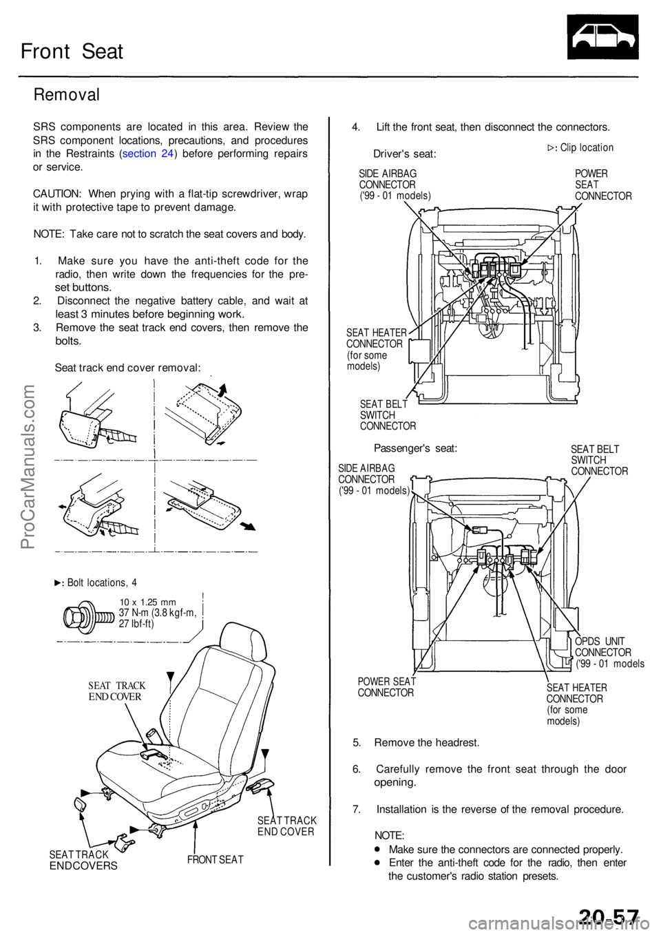
3. Remov e th e sea t trac k en d covers , the n remov e th e
bolts .
Seat trac k en d cove r removal :
Bolt locations , 4
1 0 x 1.2 5 mm37 N- m (3. 8 kgf-m ,
2 7 Ibf-ft )
SEA T TRAC K
END COVE R
SEAT TRAC K
EN D COVE R
SEA T TRAC K
END COVER S FRON T SEA T
4. Lif t th e fron t seat , the n disconnec t th e connectors .
Driver' s seat :
SIDE AIRBA G
CONNECTO R
('9 9 - 0 1 models )
SEAT HEATE RCONNECTO R(for som e
models )
SEAT BEL TSWITC HCONNECTO R
Passenger's seat :
SIDE AIRBA GCONNECTO R('99 - 0 1 models ) Cli
p locatio n
POWERSEATCONNECTO R
SEA T BEL T
SWITC H
CONNECTO R
POWER SEA TCONNECTO R
5. Remov e th e headrest .
6 . Carefull y remov e th e fron t sea t throug h th e doo r
opening .
7. Installatio n i s th e revers e o f th e remova l procedure .
NOTE:
Make sur e th e connector s ar e connecte d properly .
Ente r th e anti-thef t cod e fo r th e radio , the n ente r
th e customer' s radi o statio n presets .
SEAT HEATE RCONNECTO R
(fo r som e
models )
OPD
S UNI T
CONNECTO R
('9 9 - 0 1 model s
ProCarManuals.com
Page 1471 of 1954
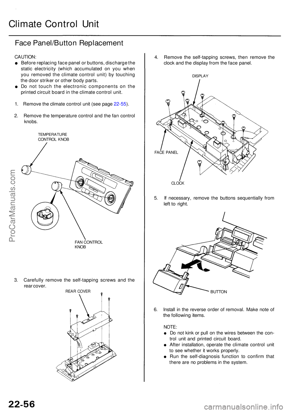
Climate Contro l Uni t
Face Panel/Butto n Replacemen t
CAUTION:
Before replacin g fac e pane l o r buttons , discharg e th e
stati c electricit y (whic h accumulate d o n yo u whe n
yo u remove d th e climat e contro l unit ) b y touchin g
th e doo r strike r o r othe r bod y parts .
D o no t touc h th e electroni c component s o n th e
printe d circui t boar d in th e climat e contro l unit .
1 . Remov e th e climat e contro l uni t (se e pag e 22-55 ).
2 . Remov e th e temperatur e contro l an d th e fa n contro l
knobs.
TEMPERATUR ECONTROL KNO B
FAN CONTRO LKNOB
3. Carefull y remov e th e self-tappin g screw s an d th e
rea r cover .
REAR COVE R
4. Remov e th e self-tappin g screws , the n remov e th e
cloc k an d th e displa y fro m th e fac e panel .
DISPLA Y
CLOCK
5. I f necessary , remov e th e button s sequentiall y fro m
left t o right .
BUTTO N
6. Instal l i n th e revers e orde r o f removal . Mak e not e o f
the followin g items .
NOTE :
Do no t kin k o r pul l o n th e wire s betwee n th e con -
tro l uni t an d printe d circui t board .
Afte r installation , operat e th e climat e contro l uni t
t o se e whethe r i t work s properly .
Ru n th e self-diagnosi s functio n t o confir m tha t
ther e ar e n o problem s in th e system .
FACE PANE L
ProCarManuals.com
Page 1484 of 1954
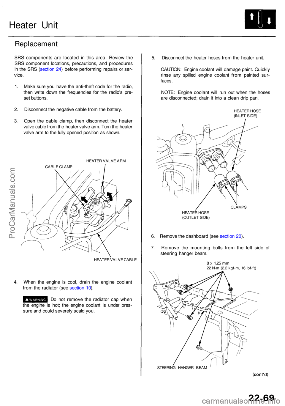
Heater Uni t
Replacemen t
SRS component s ar e locate d i n thi s area . Revie w th e
SR S componen t locations , precautions , an d procedure s
i n th e SR S (sectio n 24 ) befor e performin g repair s o r ser -
vice.
1. Mak e sur e yo u hav e th e anti-thef t cod e fo r th e radio ,
the n writ e dow n th e frequencie s fo r th e radio' s pre -
set buttons .
2. Disconnec t th e negativ e cabl e fro m th e battery .
3 . Ope n th e cabl e clamp , the n disconnec t th e heate r
valv e cabl e fro m th e heate r valv e arm . Tur n th e heate r
valv e ar m to th e full y opene d positio n a s shown .
HEATE R VALV E AR M
CABL E CLAM P
HEATER VALV E CABL E
4. Whe n th e engin e i s cool , drai n th e engin e coolan t
fro m th e radiato r (se e sectio n 10 ).
D o no t remov e th e radiato r ca p whe n
th e engin e i s hot ; th e engin e coolan t i s unde r pres -
sur e an d coul d severel y scal d you . 5
. Disconnec t th e heate r hose s fro m th e heate r unit .
CAUTION : Engin e coolan t wil l damag e paint . Quickl y
rins e an y spille d engin e coolan t fro m painte d sur -
faces .
NOTE : Engin e coolan t wil l ru n ou t whe n th e hose s
ar e disconnected ; drai n it int o a clea n dri p pan .
HEATE R HOS E(INLE T SIDE )
CLAMP S
HEATE R HOS E
(OUTLE T SIDE )
6. Remov e th e dashboar d (se e sectio n 20 ).
7 . Remov e th e mountin g bolt s fro m th e lef t sid e o f
steerin g hange r beam .
8 x 1.2 5 mm22 N- m (2. 2 kgf-m , 1 6 Ibf-ft )
STEERIN G HANGE R BEA M
ProCarManuals.com
Page 1494 of 1954
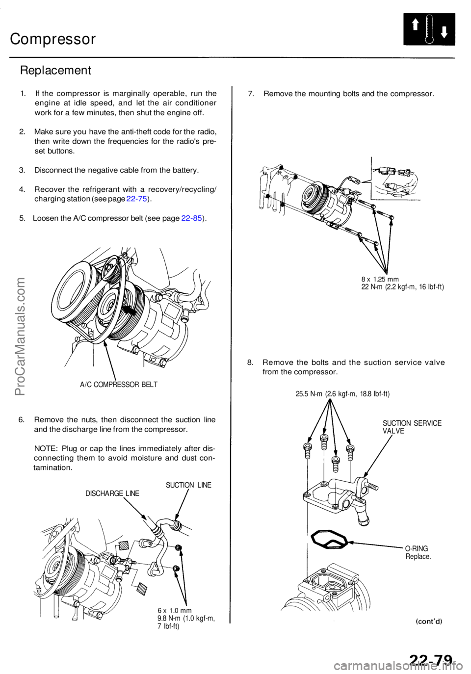
Compressor
Replacemen t
1. I f th e compresso r i s marginall y operable , ru n th e
engin e a t idl e speed , an d le t th e ai r conditione r
wor k fo r a fe w minutes , the n shu t th e engine off.
2 . Mak e sur e yo u hav e th e anti-thef t cod e fo r th e radio ,
the n writ e dow n th e frequencie s fo r th e radio' s pre -
se t buttons .
3 . Disconnec t th e negativ e cabl e fro m th e battery .
4 . Recove r th e refrigeran t wit h a recovery/recycling /
chargin g statio n (se e pag e 22-75 ).
5 . Loose n th e A/ C compresso r bel t (se e pag e 22-85 ).
A/ C COMPRESSO R BEL T
6. Remov e th e nuts , the n disconnec t th e suctio n lin e
an d th e discharg e lin e fro m th e compressor .
NOTE : Plu g o r ca p th e line s immediatel y afte r dis -
connectin g the m to avoi d moistur e an d dus t con -
tamination .
SUCTION LIN E
DISCHARG E LIN E
6 x 1. 0 m m9.8 N- m (1. 0 kgf-m ,
7 Ibf-ft )
7. Remov e th e mountin g bolt s an d th e compressor .
8 x 1.2 5 mm22 N- m (2. 2 kgf-m , 1 6 Ibf-ft )
8. Remov e th e bolt s an d th e suctio n servic e valv e
fro m th e compressor .
25.5 N- m (2. 6 kgf-m , 18. 8 Ibf-ft )
SUCTIO N SERVIC E
VALV E
O-RIN G
Replace .
ProCarManuals.com