steering ACURA RL KA9 1996 Service Service Manual
[x] Cancel search | Manufacturer: ACURA, Model Year: 1996, Model line: RL KA9, Model: ACURA RL KA9 1996Pages: 1954, PDF Size: 61.44 MB
Page 1230 of 1954
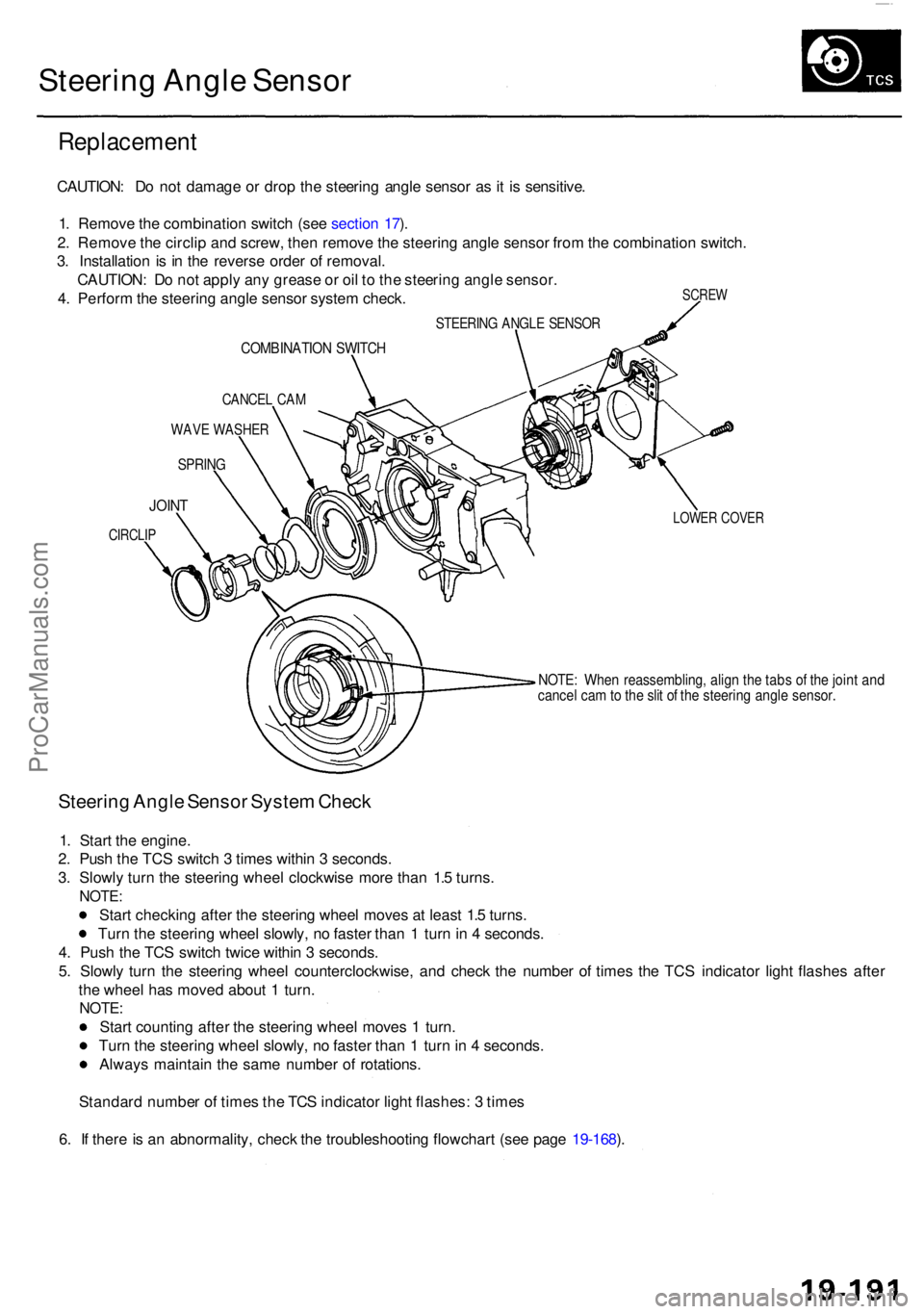
Steering Angl e Senso r
Replacemen t
SCREW
CAUTION : D o no t damag e o r dro p th e steerin g angl e senso r a s it i s sensitive .
1 . Remov e th e combinatio n switc h (se e sectio n 17 ).
2 . Remov e th e circli p an d screw , the n remov e th e steerin g angl e senso r fro m th e combinatio n switch .
3 . Installatio n i s i n th e revers e orde r o f removal .
CAUTION : D o no t appl y an y greas e o r oi l t o th e steerin g angl e sensor .
4 . Perfor m th e steerin g angl e senso r syste m check .
STEERIN G ANGL E SENSO R
COMBINATIO N SWITC H
CANCE L CA M
WAV E WASHE R
SPRING
LOWER COVE RJOINT
CIRCLI P
NOTE: Whe n reassembling , alig n th e tab s o f th e join t an dcance l ca m to th e sli t o f th e steerin g angl e sensor .
Steering Angl e Senso r Syste m Chec k
1. Star t th e engine .
2 . Pus h th e TC S switc h 3 time s withi n 3 seconds .
3 . Slowl y tur n th e steerin g whee l clockwis e mor e tha n 1. 5 turns .
NOTE :
Start checkin g afte r th e steerin g whee l move s a t leas t 1. 5 turns .
Tur n th e steerin g whee l slowly , n o faste r tha n 1 tur n in 4 seconds .
4 . Pus h th e TC S switc h twic e withi n 3 seconds .
5 . Slowl y tur n th e steerin g whee l counterclockwise , an d chec k th e numbe r o f time s th e TC S indicato r ligh t flashe s afte r
th e whee l ha s move d abou t 1 turn .
NOTE :
Start countin g afte r th e steerin g whee l move s 1 turn .
Tur n th e steerin g whee l slowly , n o faste r tha n 1 tur n in 4 seconds .
Alway s maintai n th e sam e numbe r o f rotations .
Standar d numbe r o f time s th e TC S indicato r ligh t flashes : 3 time s
6 . I f ther e is a n abnormality , chec k th e troubleshootin g flowchar t (se e pag e 19-168 ).
ProCarManuals.com
Page 1234 of 1954

Component Locations
SERVICE CHECK CONNECTOR (2P)
RIGHT-REAR WHEEL SENSOR
VSA CONVERTER UNIT
VSA MODULATOR
CONTROL UNIT
TCS CONTROL
VALVE SENSOR
RIGHT-FRONT
WHEEL SENSOR
PRECHARGE
PUMP MOTOR
STEERING
ANGLE SENSOR
YAW RATE/LATERAL
ACCELERATION SENSOR
TCS CONTROL VALVE
ACTUATOR
UNDER-HOOD
RELAY BOX C
UNDER-HOOD
FUSE/RELAY BOX
VSA OFF SWITCH
UNDER-DASH FUSE/RELAY BOX
LEFT-FRONT WHEEL SENSOR
LEFT-REAR
WHEEL SENSOR
GAUGE ASSEMBLY
ABS INDICATOR
VSA SYSTEM INDICATOR
UNDER-HOOD FUSE/RELAY BOX
STOP/HORN
(20 A) FUSE
BRAKE SYSTEM INDICATOR
VSA ACTIVATION INDICATOR
UNDER-DASH FUSE/RELAY BOX
TCS
(15 A) FUSE
VSA
(20 A) FUSE
METER
(15 A) FUSE
ECU
(20 A) FUSE
METER
(7.5 A) FUSE
BATTERY
(120 A) FUSE
VSA MOTOR (40 A) FUSE
IG SW (50 A) FUSE
UNDER-HOOD RELAY BOX C
FAIL-SAFE RELAY
GAUGE RELAY
PCM
R/C MIRROR
(7.5 A) FUSEProCarManuals.com
Page 1263 of 1954
Troubleshooting
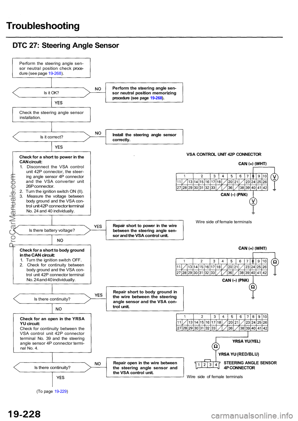
DTC 27: Steering Angle Sensor
Perform the steering angle sen-
sor neutral position check proce-
dure (see page 19-268).
Is it OK?
Check the steering angle sensor
installation.
Is it correct?
Check for a short to power in the CAN circuit:
1. Disconnect the VSA control unit 42P connector, the steer-
ing angle sensor 4P connector
and the VSA converter unit
26P connector.2. Turn the ignition switch ON (II).
3. Measure the voltage between body ground and the VSA con-
trol unit 42P connector terminalNo. 24 and 40 individually.
Is there battery voltage?
Is there continuity?
Check for an open in the YRSA
YU circuit:
Check for continuity between the
VSA control unit 42P connector
terminal No. 39 and the steering angle sensor 4P connector termi-
nal No. 4.
Is there continuity?
(To page 19-229)
Perform the steering angle sen-
sor neutral position memorizing
procedure (see page 19-268).
Install the steering angle sensorcorrectly.
VSA CONTROL UNIT 42P CONNECTOR
Repair short to power in the wire
between the steering angle sen-
sor and the VSA control unit.
Wire side of female terminals
Repair short to body ground in
the wire between the steeringangle sensor and the VSA con-trol unit.
Repair open in the wire between
the steering angle sensor and the VSA control unit.STEERING ANGLE SENSOR4P CONNECTOR
Wire side of female terminals
Check for a short to body ground
in the CAN circuit:1. Turn the ignition switch OFF.
2. Check for continuity between body ground and the VSA con-
trol unit 42P connector terminal
No. 24 and 40 individually.
(RED/BLU)
ProCarManuals.com
Page 1264 of 1954
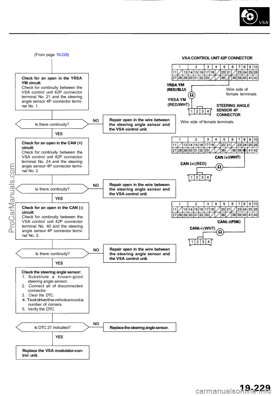
(From page 19-228)
Check for an open in the YRSAYM circuit:
Check for continuity between the
VSA control unit 42P connector
terminal No. 21 and the steering angle sensor 4P connector termi-
nal No. 1.
Is there continuity?
Check for an open in the CAN (+)
circuit:
Check for continuity between the
VSA control unit 42P connector
terminal No. 24 and the steering angle sensor 4P connector termi-
nal No. 2.
Is there continuity?
Check for an open in the CAN (-)
circuit: Check for continuity between the
VSA control unit 42P connector
terminal No. 40 and the steering angle sensor 4P connector termi-
nal No. 3.
Is there continuity?
Check the steering angle sensor: 1. S u b s t i t u t e a k n o w n - g o o d steering angle sensor.
2. Connect all of disconnected connector.
3. Clear the DTC.4. Test drive the vehicle around anumber of corners.
5. Verify the DTC.
Is DTC 27 indicated? VSA CONTROL UNIT 42P CONNECTOR
Repair open in the wire between
the steering angle sensor and
the VSA control unit. Wire side of
female terminals
STEERING ANGLESENSOR 4PCONNECTOR
Wire side of female terminals
Replace the steering angle sensor.
Repair open in the wire between
the steering angle sensor and
the VSA control unit.
Repair open in the wire between
the steering angle sensor and
the VSA control unit.
Replace the VSA modulator-con-
trol unit.
YRSA YM
(RED/WHT)
(RED)
(WHT)
ProCarManuals.com
Page 1286 of 1954
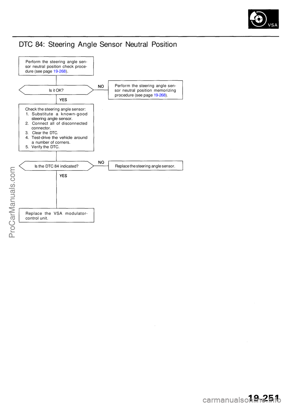
DTC 84 : Steerin g Angl e Senso r Neutra l Positio n
Perform th e steerin g angl e sen -
so r neutra l positio n chec k proce -
dur e (se e pag e 19-268 ).
Is it OK ?Perfor m th e steerin g angl e sen -
so r neutra l positio n memorizin g
procedur e (se e pag e 19-268 ).
Chec k th e steerin g angl e sensor :
1. Substitut e a known-goo dsteering angl e sensor .2. Connec t al l o f disconnecte d
connector .
3. Clea r th e DTC .4. Test-driv e th e vehicl e aroun da numbe r o f corners .
5 . Verif y th e DTC .
I s th e DT C 8 4 indicated ? Replac
e th e steerin g angl e sensor .
Replac e th e VS A modulator -
contro l unit .
ProCarManuals.com
Page 1292 of 1954
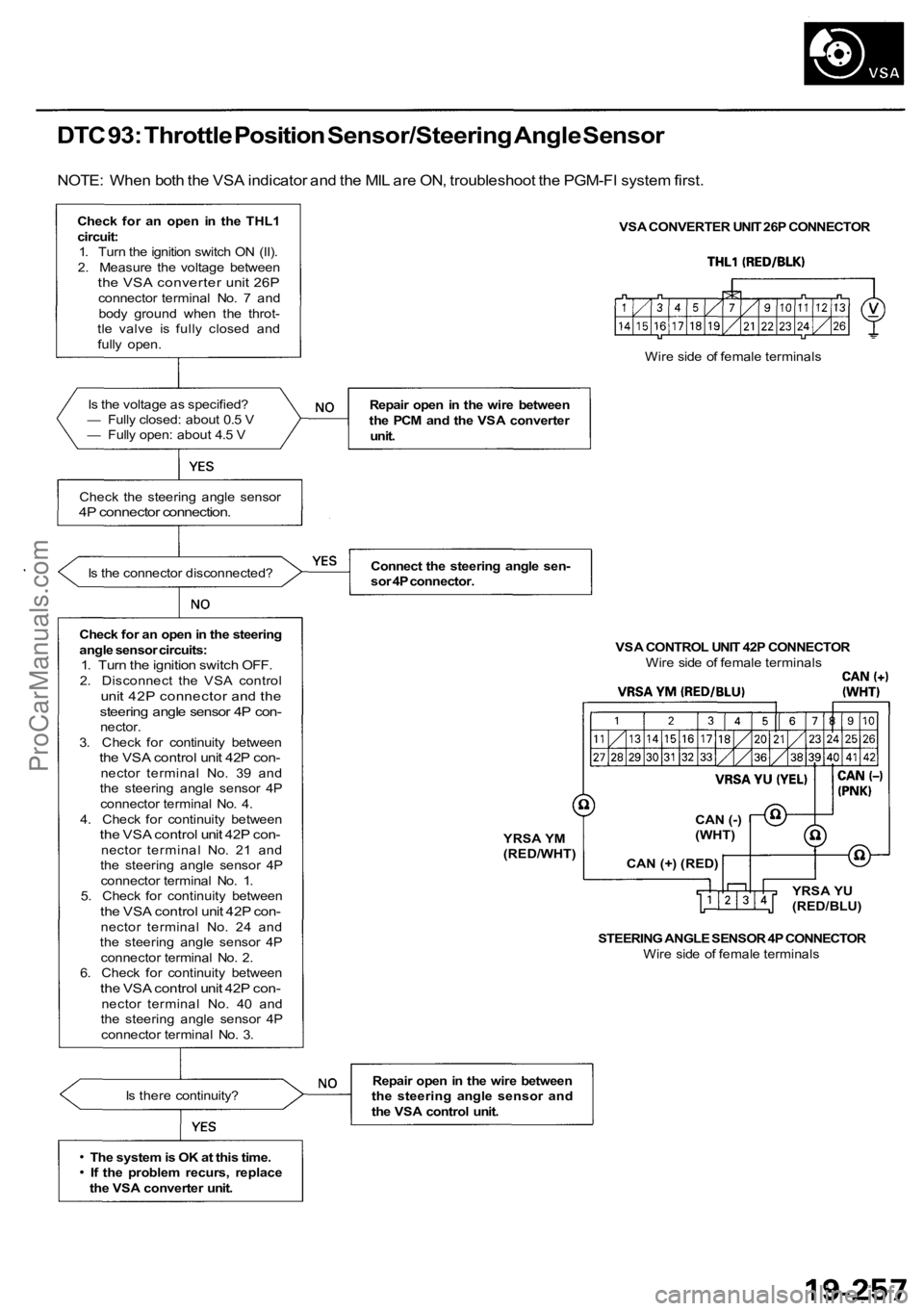
DTC 93: Throttle Position Sensor/Steering Angle Sensor
NOTE: When both the VSA indicator and the MIL are ON, troubleshoot the PGM-FI system first.
Check for an open in the THL1circuit:1. Turn the ignition switch ON (II).
2. Measure the voltage between
the VSA converter unit 26Pconnector terminal No. 7 and body ground when the throt-
tle valve is fully closed and
fully open.
Is the voltage as specified?
— Fully closed: about 0.5 V
— Fully open: about 4.5 V
Check the steering angle sensor
4P connector connection.
Is the connector disconnected?
Check for an open in the steering
angle sensor circuits:
1. Turn the ignition switch OFF.2. Disconnect the VSA controlunit 42P connector and thesteering angle sensor 4P con-nector.
3. Check for continuity between
the VSA control unit 42P con-nector terminal No. 39 and
the steering angle sensor 4P
connector terminal No. 4.
4. Check for continuity between
the VSA control unit 42P con-nector t e r m i n a l No. 21 and
the steering angle sensor 4P
connector terminal No. 1.
5. Check for continuity between
the VSA control unit 42P con-nector terminal No. 24 and
the steering angle sensor 4P
connector terminal No. 2.
6. Check for continuity between
the VSA control unit 42P con-nector terminal No. 40 and
the steering angle sensor 4P
connector terminal No. 3.
Is there continuity?
The system is OK at this time. If the problem recurs, replace
the VSA converter unit. VSA CONVERTER UNIT 26P CONNECTOR
Repair open in the wire between
the PCM and the VSA converter unit.
Connect the steering angle sen-
sor 4P connector. VSA CONTROL UNIT 42P CONNECTORWire side of female terminals
STEERING ANGLE SENSOR 4P CONNECTOR Wire side of female terminals
Repair open in the wire between
the steering angle sensor and
the VSA control unit. Wire side of female terminals
YRSA YM
(RED/WHT) CAN (-)
(WHT)
CAN (+) (RED) YRSA YU
(RED/BLU)
ProCarManuals.com
Page 1302 of 1954
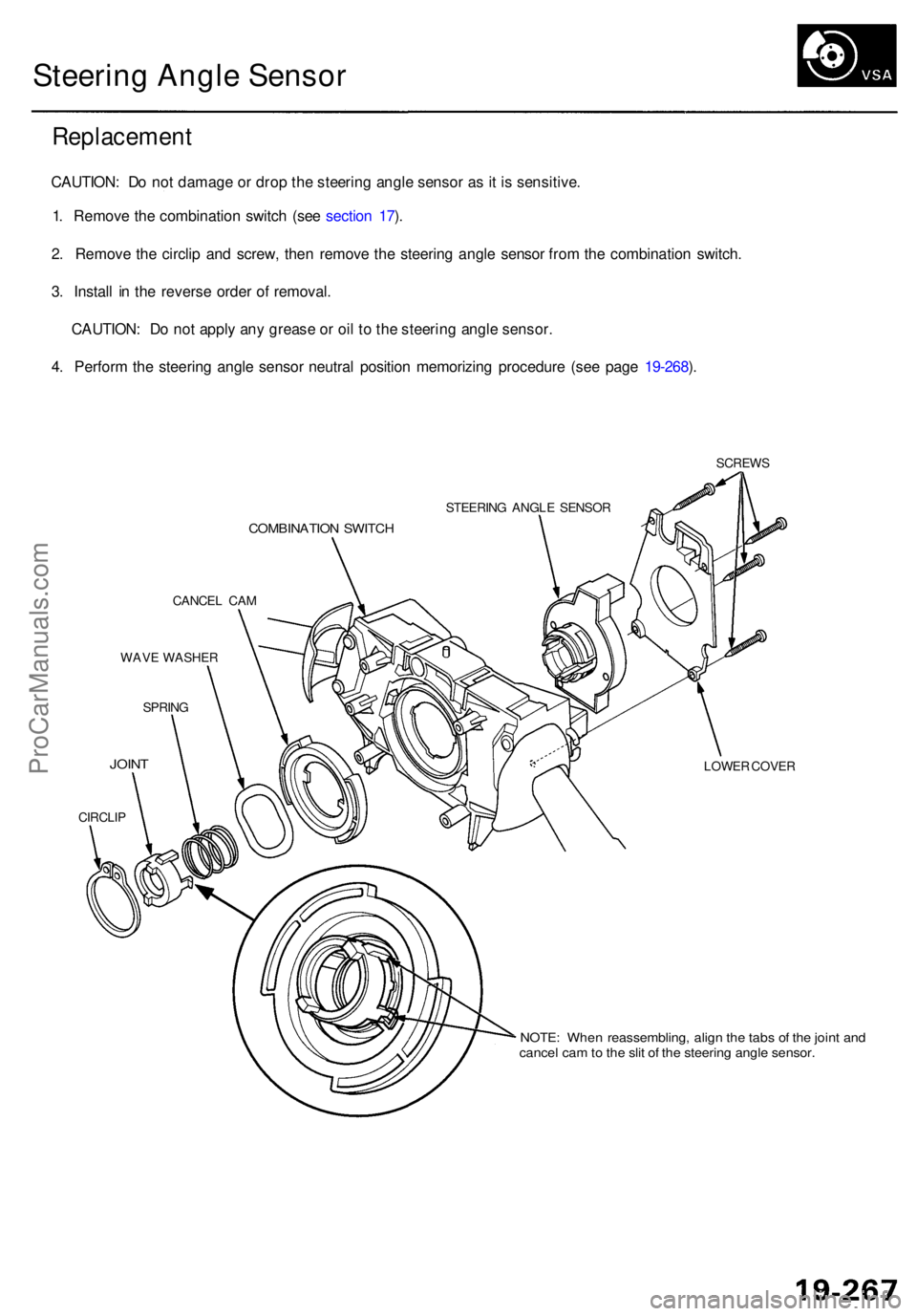
Steering Angl e Senso r
Replacemen t
CAUTION: D o no t damag e o r dro p th e steerin g angl e senso r a s it i s sensitive .
1 . Remov e th e combinatio n switc h (se e sectio n 17 ).
2 . Remov e th e circli p an d screw , the n remov e th e steerin g angl e senso r fro m th e combinatio n switch .
3 . Instal l i n th e revers e orde r o f removal .
CAUTION : D o no t appl y an y greas e o r oi l t o th e steerin g angl e sensor .
4 . Perfor m th e steerin g angl e senso r neutra l positio n memorizin g procedur e (se e pag e 19-268 ).
SCREW S
STEERIN G ANGL E SENSO R
COMBINATIO N SWITC H
CANCEL CA M
WAV E WASHE R
SPRIN G
JOINTLOWE R COVE R
CIRCLI P
NOTE: Whe n reassembling , align the tab s o f th e join t an dcance l ca m to th e sli t o f th e steerin g angl e sensor .
ProCarManuals.com
Page 1303 of 1954
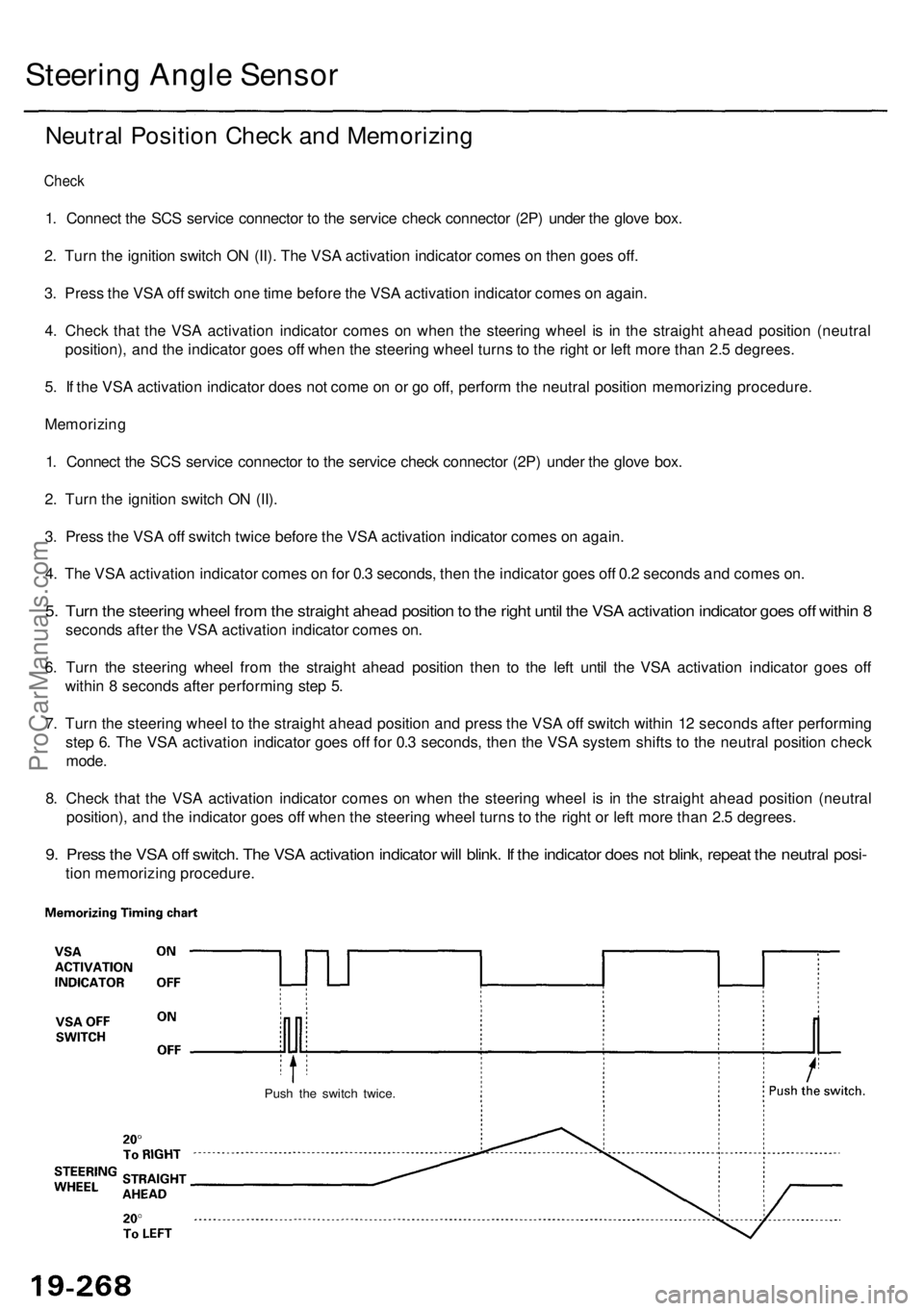
Steering Angl e Senso r
Neutral Positio n Chec k an d Memorizin g
Check
1. Connec t th e SC S servic e connecto r t o th e servic e chec k connecto r (2P ) unde r th e glov e box .
2 . Tur n th e ignitio n switc h O N (II) . Th e VS A activatio n indicato r come s o n the n goe s off .
3 . Pres s th e VS A of f switc h on e tim e befor e th e VS A activatio n indicato r come s o n again .
4 . Chec k tha t th e VS A activatio n indicato r come s o n whe n th e steerin g whee l i s i n th e straigh t ahea d positio n (neutra l
position) , an d th e indicato r goe s of f whe n th e steerin g whee l turn s t o th e righ t o r lef t mor e tha n 2. 5 degrees .
5 . I f th e VS A activatio n indicato r doe s no t com e o n o r g o off , perfor m th e neutra l positio n memorizin g procedure .
Memorizin g
1 . Connec t th e SC S servic e connecto r t o th e servic e chec k connecto r (2P ) unde r th e glov e box .
2 . Tur n th e ignitio n switc h O N (II) .
3 . Pres s th e VS A of f switc h twic e befor e th e VS A activatio n indicato r come s o n again .
4 . Th e VS A activatio n indicato r come s o n fo r 0. 3 seconds , the n th e indicato r goe s of f 0. 2 second s an d come s on .
5. Tur n th e steerin g whee l fro m th e straigh t ahea d positio n to th e righ t unti l th e VS A activatio n indicato r goe s of f withi n 8
second s afte r th e VS A activatio n indicato r come s on .
6 . Tur n th e steerin g whee l fro m th e straigh t ahea d positio n the n t o th e lef t unti l th e VS A activatio n indicato r goe s of f
withi n 8 second s afte r performin g ste p 5 .
7 . Tur n th e steerin g whee l t o th e straigh t ahea d positio n an d press the VS A of f switc h withi n 1 2 second s afte r performin g
ste p 6 . Th e VS A activatio n indicato r goe s of f fo r 0. 3 seconds , the n th e VS A syste m shift s t o th e neutra l positio n chec k
mode .
8 . Chec k tha t th e VS A activatio n indicato r come s o n whe n th e steerin g whee l i s i n th e straigh t ahea d positio n (neutra l
position) , an d th e indicato r goe s of f whe n th e steerin g whee l turn s t o th e righ t o r lef t mor e tha n 2. 5 degrees .
9. Pres s th e VS A of f switch . Th e VS A activatio n indicato r wil l blink . I f th e indicato r doe s no t blink , repea t th e neutra l posi -
tion memorizin g procedure .
Push th e switc h twice .
ProCarManuals.com
Page 1547 of 1954
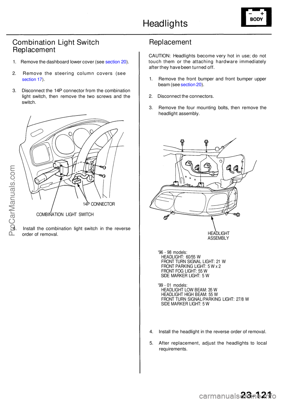
Headlights
Combinatio n Ligh t Switc h
Replacemen t
1. Remov e th e dashboar d lowe r cove r (se e sectio n 20 ).
2 . Remove the steering column covers (see
section 17 ).
3 . Disconnec t th e 14 P connecto r fro m th e combinatio n
ligh t switch , the n remov e th e tw o screw s an d th e
switch .
4 . Instal l th e combinatio n ligh t switc h i n th e revers e
orde r o f removal .
COMBINATIO N LIGH T SWITC H
14
P CONNECTO R
Replacemen t
CAUTION: Headlight s becom e ver y ho t i n use ; d o no t
touc h the m o r th e attachin g hardwar e immediatel y
afte r the y hav e bee n turne d off .
1 . Remov e th e fron t bumpe r an d fron t bumpe r uppe r
bea m (se e sectio n 20 ).
2 . Disconnec t th e connectors .
3 . Remov e th e fou r mountin g bolts , the n remov e th e
headligh t assembly .
HEADLIGH T
ASSEMBL Y
'9 6 - 9 8 models :
HEADLIGHT : 60/5 5 W
FRON T TUR N SIGNA L LIGHT : 2 1 W
FRON T PARKIN G LIGHT : 5 W x 2
FRON T FO G LIGHT : 5 5 W
SID E MARKE R LIGHT : 5 W
'9 9 - 0 1 models :
HEADLIGH T LO W BEAM : 3 5 W
HEADLIGH T HIG H BEAM : 5 5 W
FRON T TUR N SIGNAL/PARKIN G LIGHT : 27/ 8 W
SID E MARKE R LIGHT : 5 W
4. Instal l th e headligh t i n th e revers e orde r o f removal .
5 . Afte r replacement , adjus t th e headlight s t o loca l
requirements .
ProCarManuals.com
Page 1578 of 1954
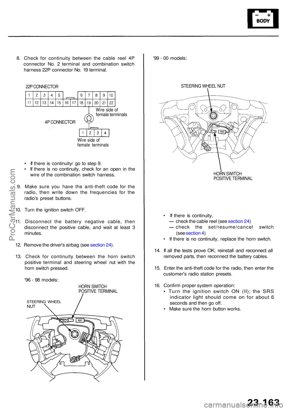
8. Chec k fo r continuit y betwee n th e cabl e ree l 4 P
connecto r No . 2 termina l an d combinatio n switc h
harnes s 22 P connecto r No . 1 9 terminal .
22P CONNECTO R
4 P CONNECTO R
Wir e sid e o f
femal e terminal s
Wir
e sid e o f
femal e terminal s
• I f ther e i s continuity / g o t o ste p 9 .
• I f ther e i s n o continuity , chec k fo r a n ope n i n th e
wir e o f th e combinatio n switc h harness .
9 . Mak e sur e yo u hav e th e anti-thef t cod e fo r th e
radio , the n writ e dow n th e frequencie s fo r th e
radio' s prese t buttons .
10 . Tur n th e ignitio n switc h OFF .
11 . Disconnec t th e batter y negativ e cable , the n
disconnec t th e positiv e cable , an d wai t a t leas t 3
minutes .
12 . Remov e th e driver' s airba g (se e sectio n 24 ).
13 . Chec k fo r continuit y betwee n th e hor n switc h
positiv e termina l an d steerin g whee l nu t wit h th e
hor n switc h pressed .
HORN SWITC H
POSITIV E TERMINA L
STEERING WHEE LNUT
'96 - 9 8 models : '9
9 - 0 0 models :
STEERIN G WHEE L NU T
HOR N SWITC H
POSITIV E TERMINA L
• I f ther e i s continuity ,
chec k th e cabl e ree l (se e sectio n 24 )
chec k th e set/resume/cance l switc h
(se e sectio n 4 )
• I f ther e i s n o continuity , replac e th e hor n switch .
14. I f al l th e test s prov e OK , reinstal l an d reconnec t al l
remove d parts , the n reconnec t th e batter y cables .
15 . Ente r th e anti-thef t cod e fo r th e radio , the n ente r th e
customer' s radi o statio n presets .
16 . Confir m prope r syste m operation :
• Tur n th e ignitio n switc h O N (II) ; th e SR S
indicato r ligh t shoul d com e o n fo r abou t 6
second s an d the n g o off .
• Mak e sur e th e hor n butto n works .
ProCarManuals.com