steering ACURA RL KA9 1996 Service Owner's Manual
[x] Cancel search | Manufacturer: ACURA, Model Year: 1996, Model line: RL KA9, Model: ACURA RL KA9 1996Pages: 1954, PDF Size: 61.44 MB
Page 985 of 1954
Steering Colum n
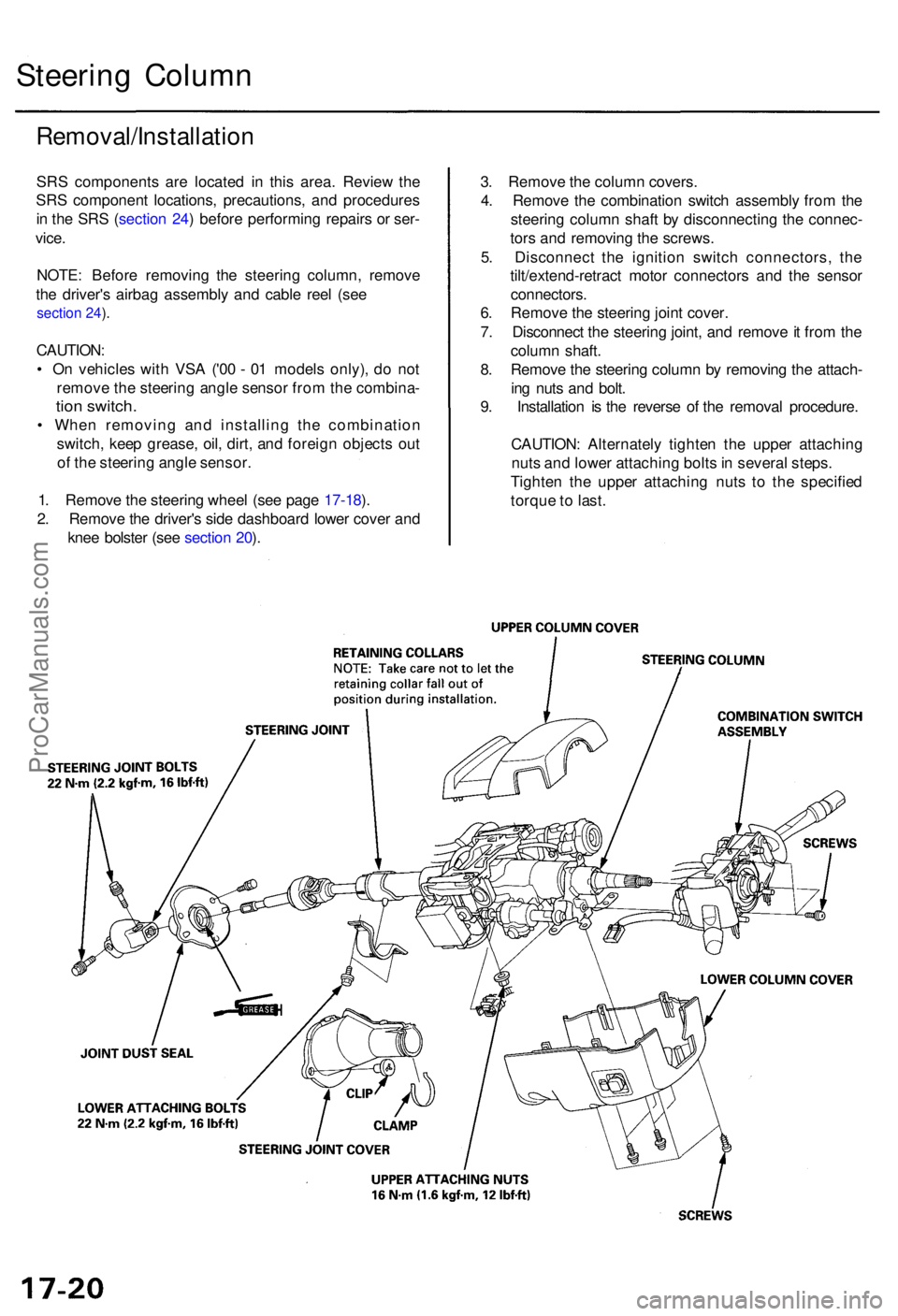
Removal/Installatio n
SRS component s ar e locate d i n thi s area . Revie w th e
SR S componen t locations , precautions , an d procedure s
i n th e SR S (sectio n 24 ) befor e performin g repair s o r ser -
vice .
NOTE : Befor e removin g th e steerin g column , remov e
th e driver' s airba g assembl y an d cabl e ree l (se e
section 24 ).
CAUTION :
• O n vehicle s wit h VS A ('0 0 - 0 1 model s only) , d o no t
remov e th e steerin g angl e senso r fro m th e combina -
tion switch .
• Whe n removin g an d installin g th e combinatio n
switch , kee p grease , oil , dirt , an d foreig n object s ou t
o f th e steerin g angl e sensor .
1 . Remov e th e steerin g whee l (se e pag e 17-18 ).
2 . Remov e th e driver' s sid e dashboar d lowe r cove r an d
kne e bolste r (se e sectio n 20 ). 3
. Remov e th e colum n covers .
4 . Remov e th e combinatio n switc h assembl y fro m th e
steerin g colum n shaf t b y disconnectin g th e connec -
tor s an d removin g th e screws .
5 . Disconnec t th e ignitio n switc h connectors , th e
tilt/extend-retrac t moto r connector s an d th e senso r
connectors .
6 . Remov e th e steerin g join t cover .
7 . Disconnec t th e steerin g joint , an d remov e it fro m th e
colum n shaft .
8 . Remov e th e steerin g colum n b y removin g th e attach -
in g nut s an d bolt .
9 . Installatio n i s th e revers e o f th e remova l procedure .
CAUTION : Alternatel y tighte n th e uppe r attachin g
nut s an d lowe r attachin g bolt s in severa l steps .
Tighte n th e uppe r attachin g nut s t o th e specifie d
torqu e to last .
ProCarManuals.com
Page 986 of 1954
NOTE:
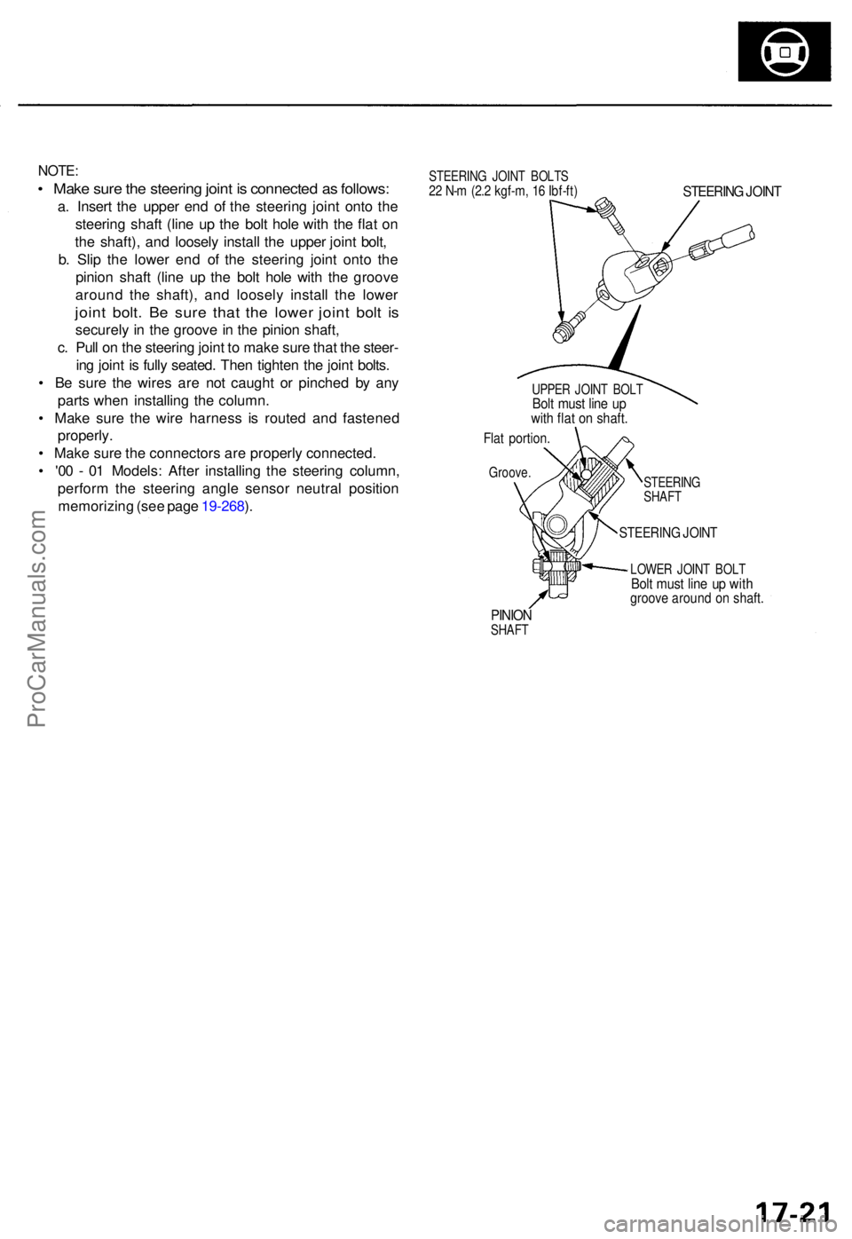
• Mak e sur e th e steerin g join t i s connecte d a s follows :
a. Inser t th e uppe r en d o f th e steerin g join t ont o th e
steerin g shaf t (lin e u p th e bol t hol e wit h th e fla t o n
th e shaft) , an d loosel y instal l th e uppe r join t bolt ,
b . Sli p th e lowe r en d o f th e steerin g join t ont o th e
pinio n shaf t (lin e u p th e bol t hol e wit h th e groov e
aroun d th e shaft) , an d loosel y instal l th e lowe r
joint bolt . B e sur e tha t th e lowe r join t bol t i s
securel y i n th e groov e in th e pinio n shaft ,
c . Pul l o n th e steerin g join t t o mak e sur e tha t th e steer -
in g join t i s full y seated . The n tighte n th e join t bolts .
• B e sur e th e wire s ar e no t caugh t o r pinche d b y an y
part s whe n installin g th e column .
• Mak e sur e th e wir e harnes s i s route d an d fastene d
properly .
• Mak e sur e th e connector s ar e properl y connected .
• '0 0 - 0 1 Models : Afte r installin g th e steerin g column ,
perfor m th e steerin g angl e senso r neutra l positio n
memorizin g (se e pag e 19-268 ).
STEERIN G JOIN T BOLT S22 N- m (2. 2 kgf-m , 1 6 Ibf-ft )STEERIN G JOIN T
UPPE R JOIN T BOL TBolt mus t lin e u pwit h fla t o n shaft .
Flat portion .
Groove.
STEERING
SHAF T
STEERIN G JOIN T
LOWE R JOIN T BOL TBolt mus t lin e u p wit hgroov e aroun d o n shaft .
PINIONSHAF T
ProCarManuals.com
Page 988 of 1954
Steering Loc k Replacemen t
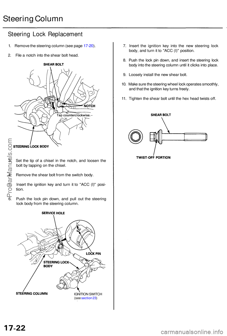
1. Remov e th e steerin g colum n (se e pag e 17-20 ).
2 . Fil e a notc h int o th e shea r bol t head .
Steerin g Colum n
7. Inser t th e ignitio n ke y int o th e ne w steerin g loc k
body , an d tur n it t o "AC C (I) " position .
8 . Pus h th e loc k pi n down , an d inser t th e steerin g loc k
bod y int o th e steerin g colum n unti l i t click s int o place .
9 . Loosel y instal l th e ne w shea r bolt .
10 . Mak e sur e th e steerin g whee l loc k operate s smoothly ,
an d tha t th e ignitio n ke y turn s freely .
11 . Tighte n th e shea r bol t unti l th e he x hea d twist s off .
3 . Se t th e ti p o f a chise l i n th e notch , an d loose n th e
bol t b y tappin g o n th e chisel .
4 . Remov e th e shea r bol t fro m th e switc h body .
5 . Inser t th e ignitio n ke y an d tur n i t t o "AC C (I) " posi -
tion.
6. Pus h th e loc k pi n down , an d pul l ou t th e steerin g
loc k bod y fro m th e steerin g column .
IGNITION SWITC H(see sectio n 23 )
ProCarManuals.com
Page 989 of 1954
Power Steering Hoses, Lines
Fluid Leakage Inspection
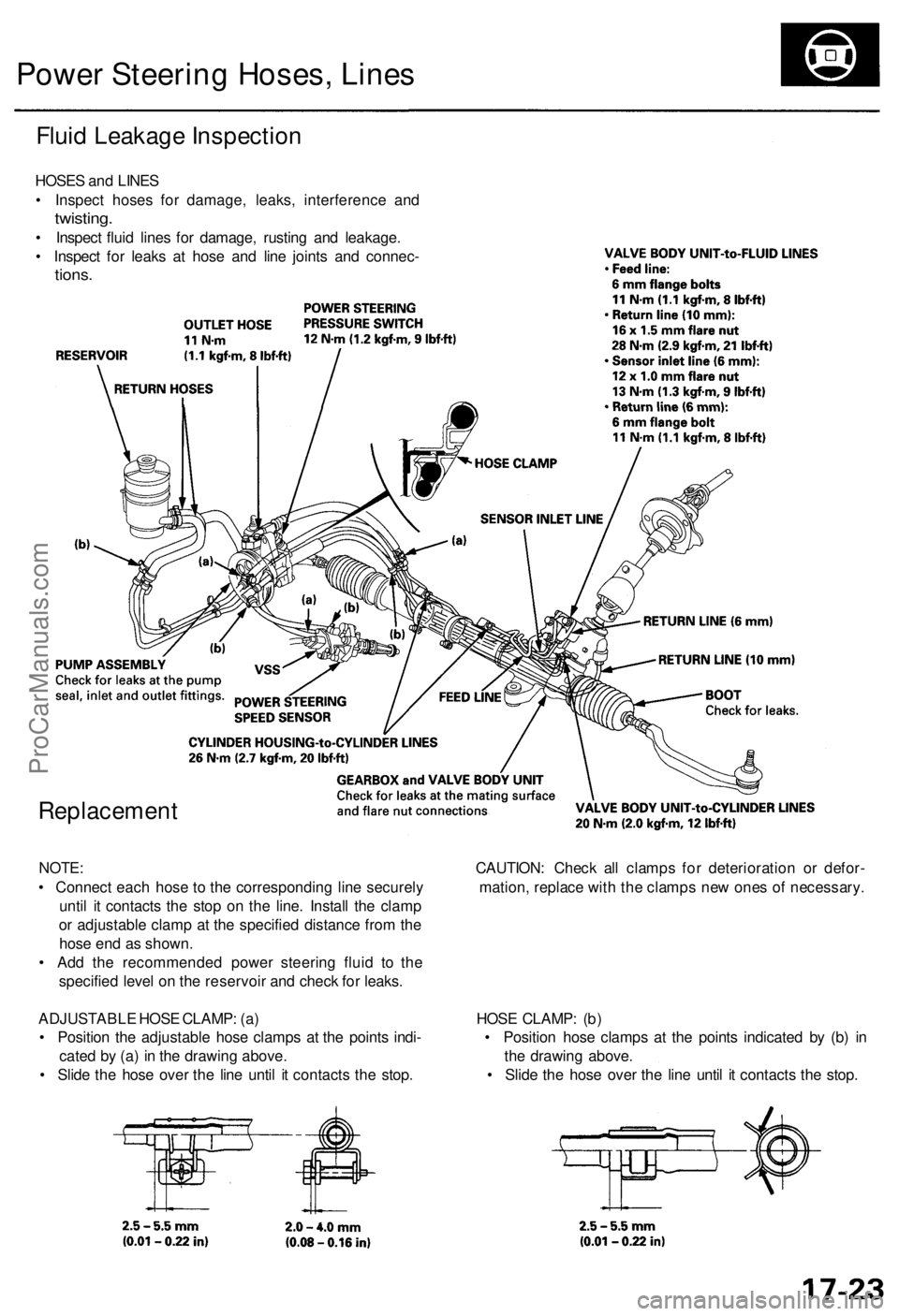
HOSES and LINES
• Inspect hoses for damage, leaks, interference and
twisting.
• Inspect fluid lines for damage, rusting and leakage.
• Inspect for leaks at hose and line joints and connec-
tions.
Replacement
NOTE: CAUTION: Check all clamps for deterioration or defor-
• Connect each hose to the corresponding line securely mation, replace with the clamps new ones of necessary.
until it contacts the stop on the line. Install the clamp
or adjustable clamp at the specified distance from the
hose end as shown.
• Add the recommended power steering fluid to the
specified level on the reservoir and check for leaks.
ADJUSTABLE HOSE CLAMP: (a) HOSE CLAMP: (b)
• Position the adjustable hose clamps at the points indi- • Position hose clamps at the points indicated by (b) in
cated by (a) in the drawing above. the drawing above.
• Slide the hose over the line until it contacts the stop. • Slide the hose over the line until it contacts the stop.ProCarManuals.com
Page 994 of 1954
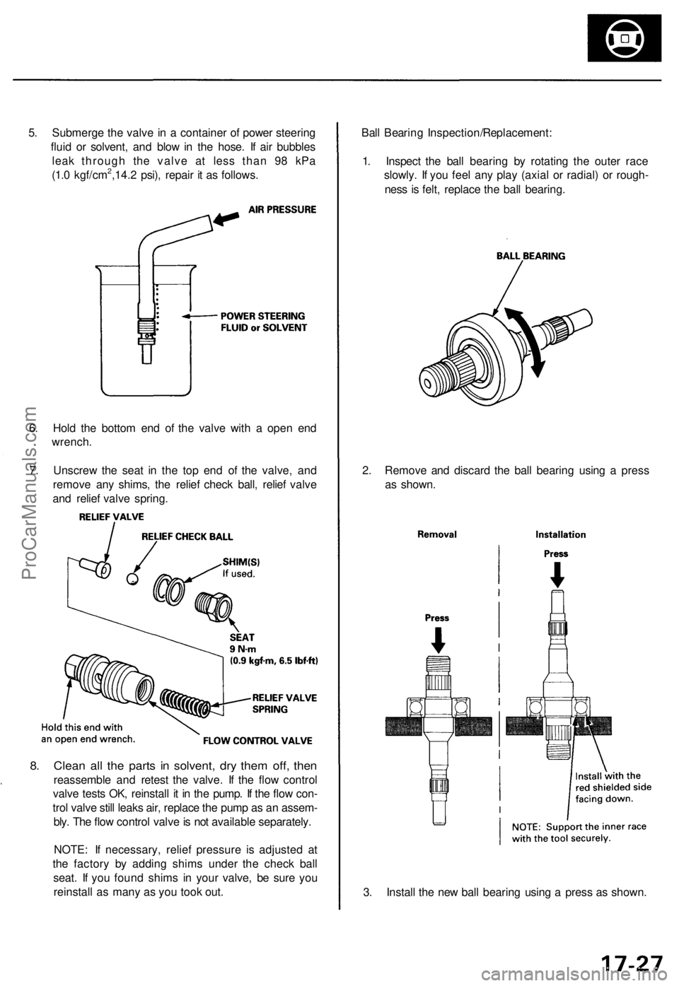
5. Submerge the valve in a container of power steering
fluid or solvent, and blow in the hose. If air bubbles
leak through the valve at less than 98 kPa
(1.0 kgf/cm2,14.2 psi), repair it as follows.
6. Hold the bottom end of the valve with a open end
wrench.
7. Unscrew the seat in the top end of the valve, and
remove any shims, the relief check ball, relief valve
and relief valve spring.
8. Clean all the parts in solvent, dry them off, then
reassemble and retest the valve. If the flow control
valve tests OK, reinstall it in the pump. If the flow con-
trol valve still leaks air, replace the pump as an assem-
bly. The flow control valve is not available separately.
NOTE: If necessary, relief pressure is adjusted at
the factory by adding shims under the check ball
seat. If you found shims in your valve, be sure you
reinstall as many as you took out.
3. Install the new ball bearing using a press as shown.
2. Remove and discard the ball bearing using a press
as shown.
Ball Bearing Inspection/Replacement:
1. Inspect the ball bearing by rotating the outer race
slowly. If you feel any play (axial or radial) or rough-
ness is felt, replace the ball bearing.ProCarManuals.com
Page 999 of 1954
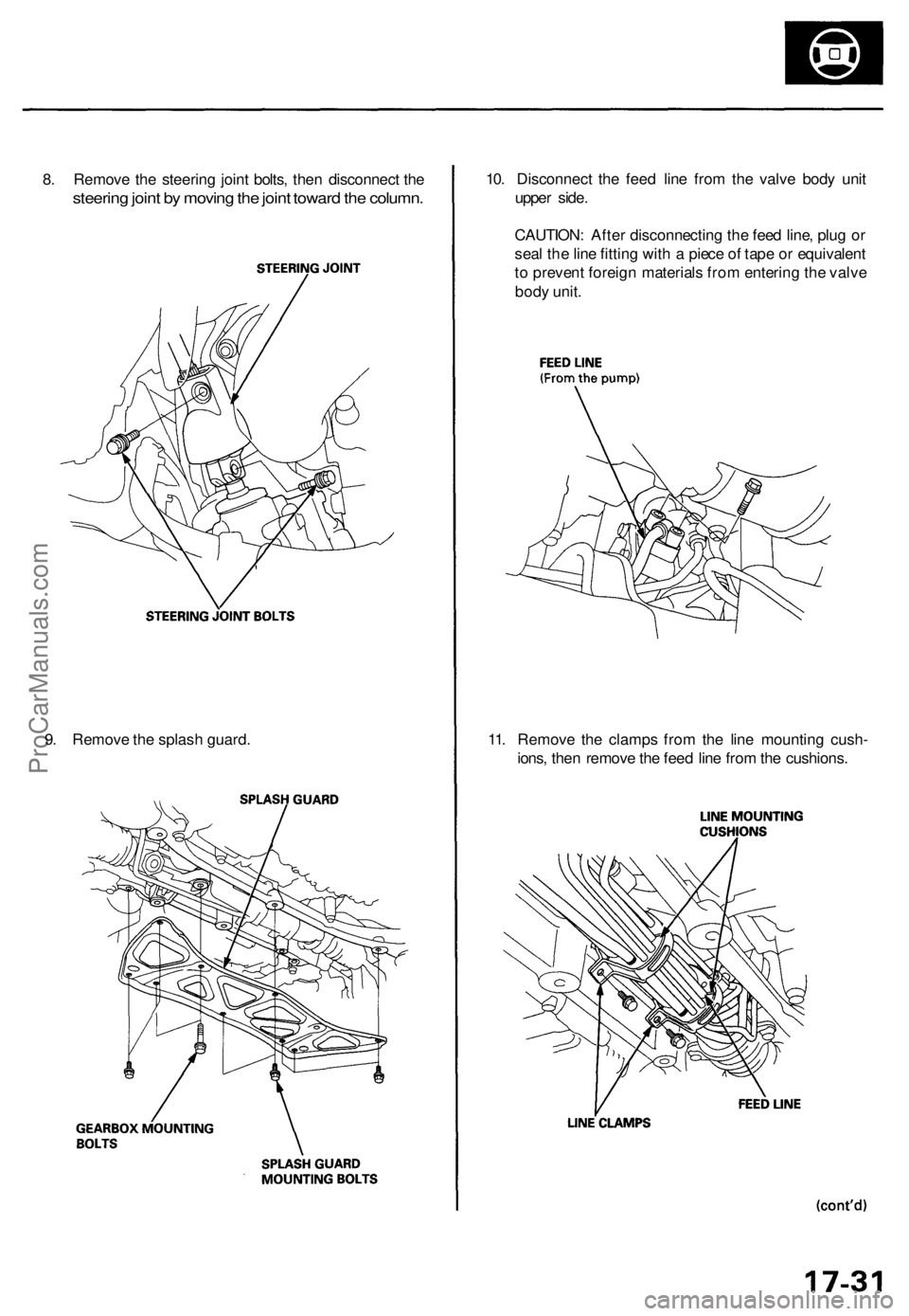
8. Remove the steering joint bolts, then disconnect the
steering joint by moving the joint toward the column.
10. Disconnect the feed line from the valve body unit
upper side.
CAUTION: After disconnecting the feed line, plug or
seal the line fitting with a piece of tape or equivalent
to prevent foreign materials from entering the valve
body unit.
11. Remove the clamps from the line mounting cush-
ions, then remove the feed line from the cushions.
9. Remove the splash guard.ProCarManuals.com
Page 1000 of 1954
Power Steering Gearbox
Removal (cont'd)
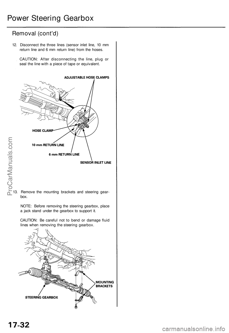
12. Disconnect the three lines (sensor inlet line, 10 mm
return line and 6 mm return line) from the hoses.
CAUTION: After disconnecting the line, plug or
seal the line with a piece of tape or equivalent.
13. Remove the mounting brackets and steering gear-
box.
NOTE: Before removing the steering gearbox, place
a jack stand under the gearbox to support it.
CAUTION: Be careful not to bend or damage fluid
lines when removing the steering gearbox.ProCarManuals.com
Page 1001 of 1954
Disassembly
Steering Rac k Disassembl y
NOTE:
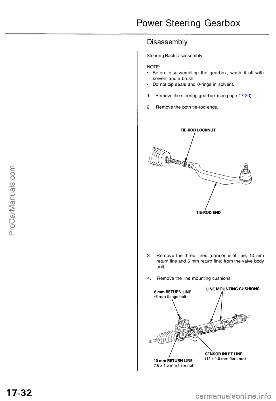
• Befor e disassemblin g th e gearbox , was h i t of f wit h
solven t an d a brush .
• D o no t di p seal s an d 0-ring s i n solvent .
1 . Remov e th e steerin g gearbo x (se e pag e 17-30 ).
2 . Remov e th e bot h tie-ro d ends .
3 . Remov e th e thre e line s (senso r inle t line , 1 0 m m
retur n lin e an d 6 m m retur n line ) fro m th e valv e bod y
unit.
4. Remov e th e lin e mountin g cushions .
Power Steerin g Gearbo x
ProCarManuals.com
Page 1002 of 1954
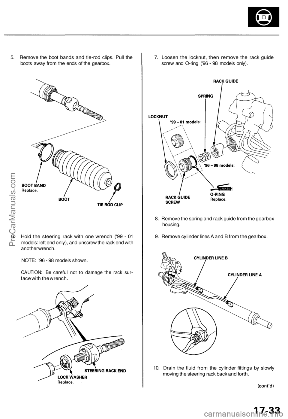
5. Remove the boot bands and tie-rod clips. Pull the
boots away from the ends of the gearbox.
6. Hold the steering rack with one wrench ('99 - 01
models: left end only), and unscrew the rack end with
another wrench.
NOTE: '96 - 98 models shown.
CAUTION: Be careful not to damage the rack sur-
face with the wrench.
7. Loosen the locknut, then remove the rack guide
screw and O-ring ('96 - 98 models only).
8. Remove the spring and rack guide from the gearbox
housing.
9. Remove cylinder lines A and B from the gearbox.
10. Drain the fluid from the cylinder fittings by slowly
moving the steering rack back and forth.ProCarManuals.com
Page 1018 of 1954
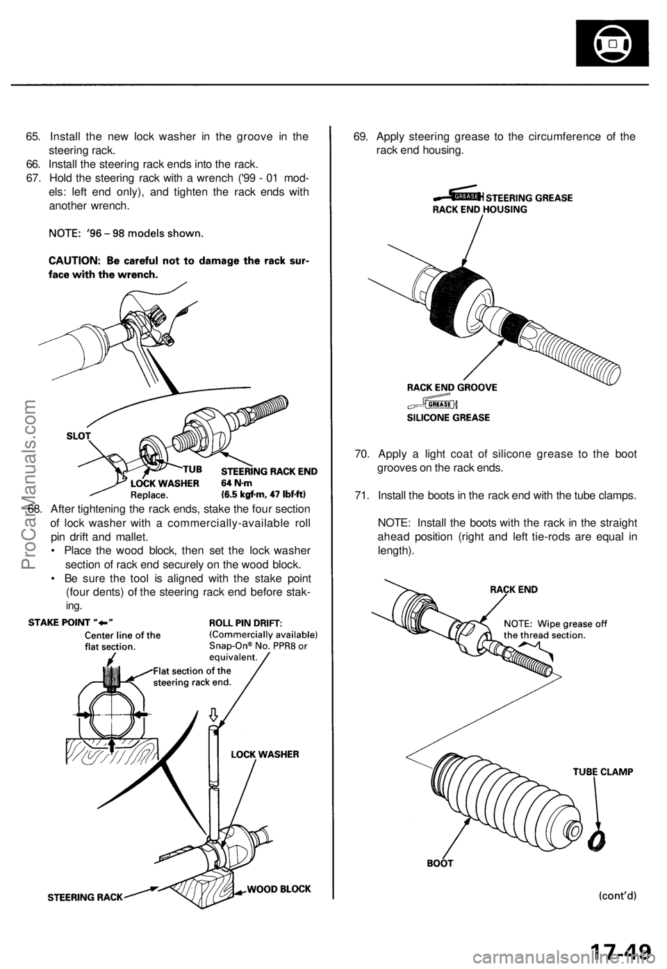
65. Install the new lock washer in the groove in the
steering rack.
66. Install the steering rack ends into the rack.
67. Hold the steering rack with a wrench ('99 - 01 mod-
els: left end only), and tighten the rack ends with
another wrench.
69. Apply steering grease to the circumference of the
rack end housing.
70. Apply a light coat of silicone grease to the boot
grooves on the rack ends.
71. Install the boots in the rack end with the tube clamps.
NOTE: Install the boots with the rack in the straight
ahead position (right and left tie-rods are equal in
length).
68. After tightening the rack ends, stake the four section
of lock washer with a commercially-available roll
pin drift and mallet.
• Place the wood block, then set the lock washer
section of rack end securely on the wood block.
• Be sure the tool is aligned with the stake point
(four dents) of the steering rack end before stak-
ing.ProCarManuals.com