steering ACURA RL KA9 1996 Service Workshop Manual
[x] Cancel search | Manufacturer: ACURA, Model Year: 1996, Model line: RL KA9, Model: ACURA RL KA9 1996Pages: 1954, PDF Size: 61.44 MB
Page 1602 of 1954
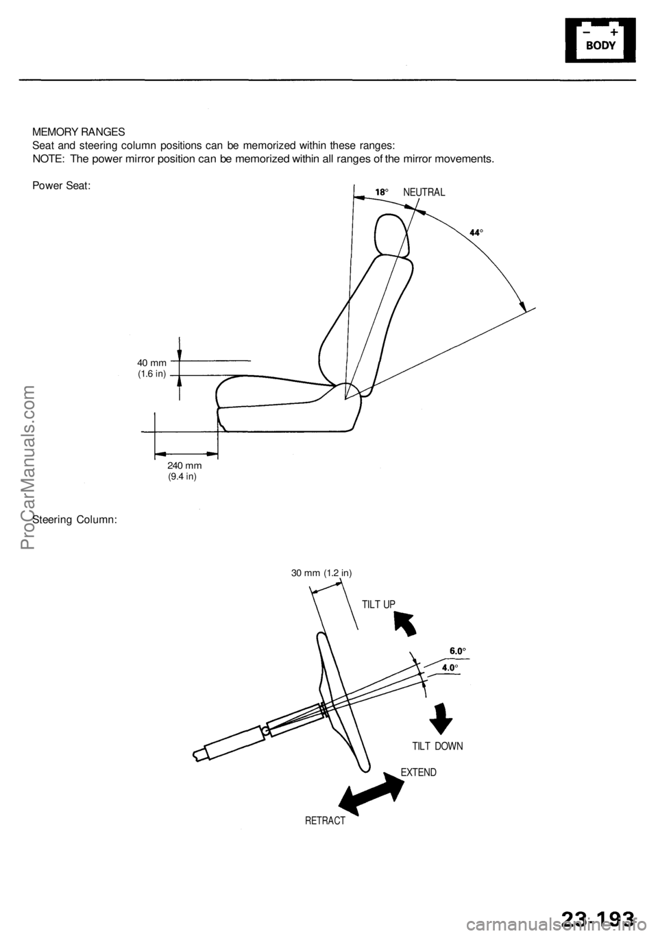
MEMORY RANGE S
Sea t an d steerin g colum n position s ca n b e memorize d withi n thes e ranges :
NOTE: Th e powe r mirro r positio n ca n b e memorize d withi n al l range s o f th e mirro r movements .
Power Seat :NEUTRA L
Steering Column :
240 m m(9. 4 in)
40 m m(1.6 in )
RETRAC T
EXTEND
TIL
T DOW N
TIL
T U P
30 m m (1. 2 in)
ProCarManuals.com
Page 1604 of 1954
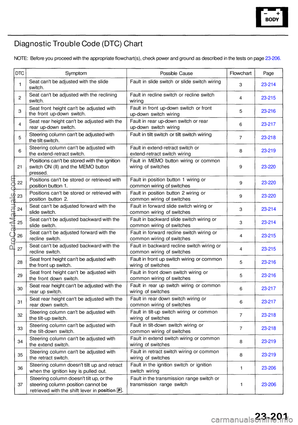
Diagnostic Troubl e Cod e (DTC ) Char t
NOTE : Befor e yo u procee d wit h th e appropriat e flowchart(s) , chec k powe r an d groun d a s describe d in th e test s o n pag e 23-206 .
DTC
1
2
3
4
5
6
21
22
23
2 4
25
26
27
2 8
2 9
30
3 1
3 2
33
3 4
35
36
37
Sympto m
Seat can' t b e adjuste d wit h th e slid e
switch .
Sea t can' t b e adjuste d wit h th e reclinin g
switch .
Sea t fron t heigh t can' t b e adjuste d wit h
th e fron t up-dow n switch .
Sea t rea r heigh t can' t b e adjuste d wit h th e
rea r up-dow n switch .
Steering colum n can' t b e adjuste d wit h
the til t switch .
Steerin g colum n can' t b e adjuste d wit h
th e extend-retrac t switch .
Position s can' t b e store d wit h th e ignitio n
switch O N (II ) an d th e MEM O butto n
pressed .
Positions can' t b e store d o r retrieve d wit h
positio n butto n 1 .
Position s can' t b e store d o r retrieve d wit h
positio n butto n 2 .
Sea t can' t b e adjuste d forwar d wit h th e
slid e switch .
Seat can' t b e adjuste d backwar d wit h th e
slid e switch .
Sea t can' t b e adjuste d forwar d wit h th e
reclin e switch .
Sea t can' t b e adjuste d backwar d wit h th e
reclin e switch .
Seat fron t heigh t can' t b e adjuste d wit h
the fron t u p switch .
Seat fron t heigh t can' t b e adjuste d wit h
th e fron t dow n switch .
Seat rea r heigh t can' t b e adjuste d wit h th e
rea r u p switch .
Sea t rea r heigh t can' t b e adjuste d wit h th e
rea r dow n switch .
Steerin g colum n can' t b e adjuste d wit h
the tilt-u p switch .
Steerin g colum n can' t b e adjuste d wit h
th e tilt-dow n switch .
Steerin g colum n can' t b e adjuste d wit h
th e exten d switch .
Steerin g colum n can' t b e adjuste d wit h
th e retrac t switch .
Steerin g colum n doesn' t
tilt up an d retrac t
whe n th e ignitio n ke y i s pulle d out .
Steerin g colum n doesn' t til t up , o r th e
steerin g colum n positio n canno t b e
retrieve d wit h th e shif t leve r i n Possibl
e Caus e
Faul t i n slid e switc h o r slid e switc h wirin g
Faul t i n reclin e switc h o r reclin e switc h
wiring
Fault i n fron t up-dow n switc h o r fron t
up-dow n switc h wirin g
Faul t i n rea r up-dow n switc h o r rea r
up-dow n switc h wirin g
Faul t
in til t switc h or tilt switc h wiring
Fault i n extend-retrac t switc h o r
extend-retrac t switc h wirin g
Faul t i n MEM O butto n wirin g o r commo n
wirin g o f switche s
Faul t i n positio n butto n 1 wirin g o r
commo n wirin g o f switche s
Fault i n positio n butto n 2 wirin g o r
commo n wirin g o f switche s
Faul t i n forwar d slid e switc h wirin g o r
commo n wirin g o f switche s
Faul t i n backwar d slid e switc h wirin g o r
commo n wirin g o f switche s
Faul t i n forwar d reclin e switc h wirin g o r
commo n wirin g o f switche s
Faul t i n backwar d reclin e switc h wirin g o r
commo n wirin g o f switche s
Fault i n fron t u p switc h wirin g o r commo n
wiring o f switche s
Faul t i n fron t dow n switc h wirin g o r
commo n wirin g o f switche s
Faul t i n rea r u p switc h wirin g o r commo n
wirin g o f switche s
Faul t i n rea r dow n switc h wirin g o r
commo n wirin g o f switche s
Faul t i n tilt-u p switc h wirin g o r commo n
wirin g o f switche s
Faul t i n tilt-dow n switc h wirin g o r
commo n wirin g o f switche s
Faul t i n exten d switc h wirin g o r commo n
wirin g o f switche s
Faul t i n retrac t switc h wirin g o r commo n
wirin g o f switche s
Faul t i n th e ignitio n switc h o r ignitio n
switc h wirin g
Faul t i n th e transmissio n rang e switc h o r
transmissio n rang e switc h
Flowchar t
3
4
5
6
7
8
9
9
9
3
3
4
4
5
5
6
6
7
7
8
8
1
1
Pag e
23-21 4
23-215
23-216
23-21 7
23-218
23-21 9
23-22 0
23-22 0
23-22 0
23-214
23-21 4
23-215
23-21 5
23-21 6
23-216
23-217
23-217
23-21 8
23-218
23-219
23-21 9
23-20 6
23-206
ProCarManuals.com
Page 1608 of 1954
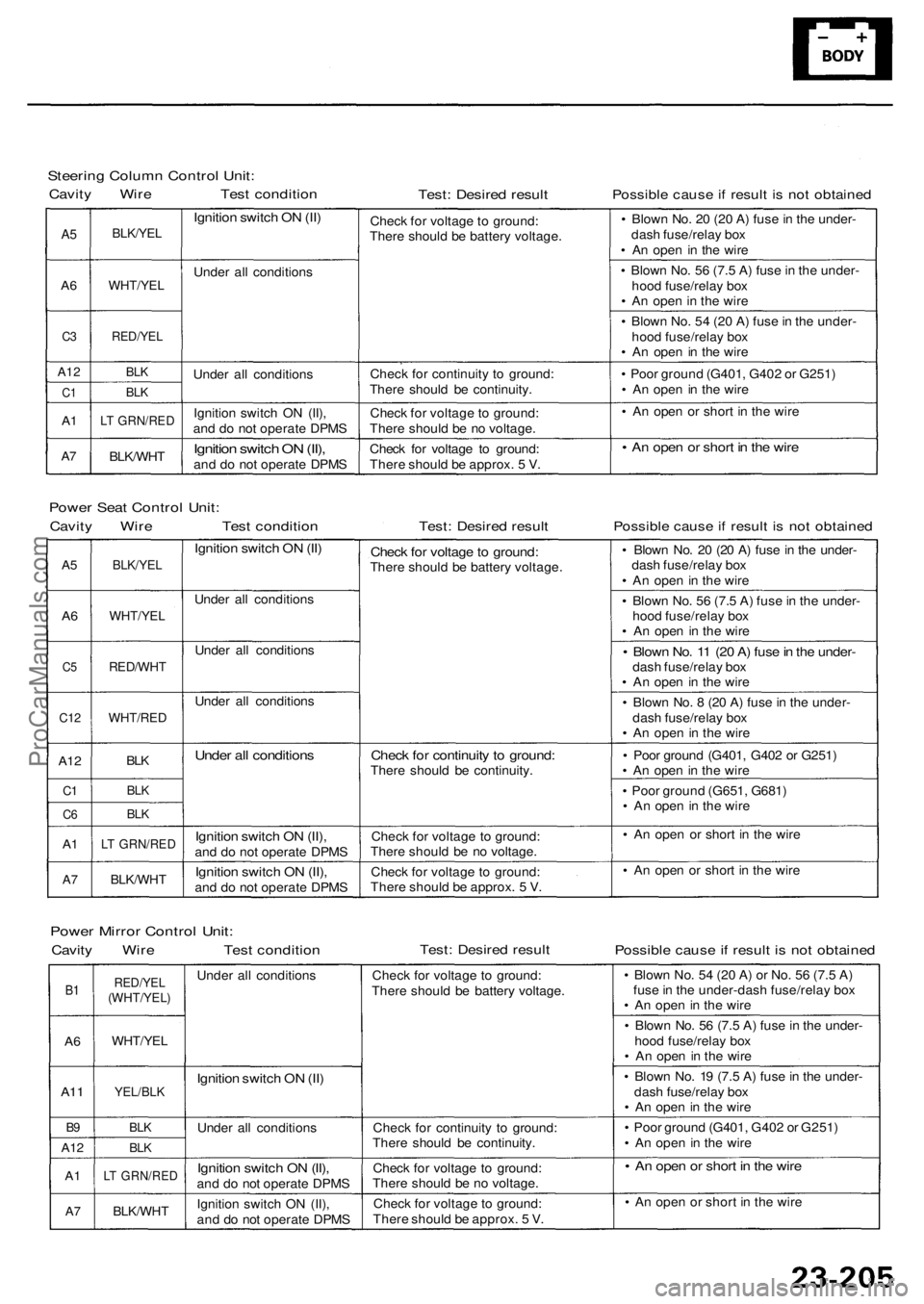
Steering Colum n Contro l Unit :
Cavit y Wir e Tes t conditio nTest: Desire d resul tPossibl e caus e if resul t i s no t obtaine d
A5
A 6
C 3
A1 2
C1
A1
A7
BLK/YE L
WHT/YE L
RED/YEL
BLK
BL K
LT GRN/RE D
BLK/WHT
Ignition switc h O N (II )
Unde r al l condition s
Unde r al l condition s
Ignitio n switc h O N (II) ,
an d d o no t operat e DPM S
Ignition switc h O N (II) ,and d o no t operat e DPM SChec
k fo r voltag e t o ground :
Ther e shoul d b e batter y voltage .
Chec k fo r continuit y t o ground :
Ther e shoul d b e continuity .
Chec k fo r voltag e to ground :
Ther e shoul d b e n o voltage .
Chec k fo r voltag e t o ground :
Ther e shoul d b e approx . 5 V . •
Blow n No . 2 0 (2 0 A ) fus e in th e under -
das h fuse/rela y bo x
• A n ope n i n th e wire
• Blow n No . 5 6 (7. 5 A ) fus e in th e under -
hoo d fuse/rela y bo x
• A n ope n in th e wir e
• Blow n No . 5 4 (2 0 A ) fus e in th e under -
hoo d fuse/rela y bo x
• A n ope n i n th e wir e
• Poo r groun d (G401 , G40 2 o r G251 )
• A n ope n in th e wir e
• A n ope n o r shor t i n th e wir e
• A n ope n o r shor t i n th e wir e
Powe r Sea t Contro l Unit :
Cavit y Wir e Tes t conditio nTest: Desire d resul tPossibl e caus e if resul t i s no t obtaine d
A5
A6
C 5
C1 2
A12
C1
C 6
A1
A 7
BLK/YE L
WHT/YE L
RED/WH T
WHT/RED
BLK
BL K
BL K
LT GRN/RE D
BLK/WHT
Ignition switc h O N (II )
Unde r al l condition s
Unde r al l condition s
Unde r al l condition s
Under al l condition s
Ignition switc h O N (II) ,and d o no t operat e DPM S
Ignitio n switc h O N (II) ,and d o no t operat e DPM S
Check fo r voltag e to ground :There shoul d b e batter y voltage .
Check fo r continuit y t o ground :There shoul d b e continuity .
Chec k fo r voltag e t o ground :
Ther e shoul d b e n o voltage .
Chec k fo r voltag e t o ground :
Ther e shoul d b e approx . 5 V . •
Blow n No . 2 0 (2 0 A ) fus e in th e under -
das h fuse/rela y bo x
• A n ope n in th e wir e
• Blow n No . 5 6 (7. 5 A ) fus e in th e under -
hoo d fuse/rela y bo x
• A n ope n i n th e wire
• Blow n No . 1 1 (2 0 A ) fus e in th e under -dash fuse/rela y bo x
• A n ope n i n th e wir e
• Blow n No . 8 (2 0 A ) fus e in th e under -
das h fuse/rela y bo x
• A n ope n in th e wir e
• Poo r groun d (G401 , G40 2 o r G251 )
• A n ope n in th e wir e
• Poo r groun d (G651 , G681 )
• A n ope n in th e wir e
• A n ope n o r shor t i n th e wir e
• A n ope n o r shor t i n th e wir e
Powe r Mirro r Contro l Unit :
Cavit y Wir e Tes t conditio nTest: Desire d resul tPossibl e caus e if resul t i s no t obtaine d
B1
A 6
A1 1
B9
A1 2
A1
A7
RED/YE L(WHT/YEL )
WHT/YEL
YEL/BLK
BLK
BLK
LT GRN/RE D
BLK/WHT
Under al l condition s
Ignition switc h O N (II )
Unde r al l condition s
Ignition switc h O N (II) ,and d o no t operat e DPM S
Ignitio n switc h O N (II) ,
an d d o no t operat e DPM SChec
k fo r voltag e t o ground :
Ther e shoul d b e batter y voltage .
Chec k fo r continuit y t o ground :
Ther e shoul d b e continuity .
Chec k fo r voltag e t o ground :
Ther e shoul d b e n o voltage .
Chec k fo r voltag e t o ground :
Ther e shoul d b e approx . 5 V . •
Blow n No . 5 4 (2 0 A ) o r No . 5 6 (7. 5 A )
fus e in th e under-das h fuse/rela y bo x
• A n ope n in th e wir e
• Blow n No . 5 6 (7. 5 A ) fus e in th e under -
hoo d fuse/rela y bo x
• A n ope n in th e wire
• Blow n No . 1 9 (7. 5 A ) fus e in th e under -
das h fuse/rela y bo x
• A n ope n in th e wir e
• Poo r groun d (G401 , G40 2 o r G251 )
• A n ope n i n th e wir e
• A n ope n o r shor t i n th e wir e
• A n ope n o r shor t i n th e wir e
ProCarManuals.com
Page 1628 of 1954
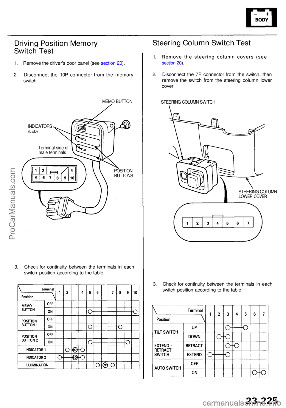
Driving Positio n Memor y
Switc h Tes t
1. Remov e th e driver' s doo r pane l (se e sectio n 20 ).
2 . Disconnec t th e 10 P connecto r fro m th e memor y
switch .
MEMO BUTTO N
INDICATOR S(LED)
Termina l sid e o fmal e terminal s
POSITIONBUTTON S
3. Chec k fo r continuit y betwee n th e terminal s i n eac h
switc h positio n accordin g t o th e table .
3. Chec k fo r continuit y betwee n th e terminal s i n eac h
switc h positio n accordin g t o th e table .
Steerin g Colum n Switc h Tes t
1. Remove the steering column covers (see
section 20 ).
2 . Disconnec t th e 7 P connecto r fro m th e switch , the n
remov e th e switc h fro m th e steerin g colum n lowe r
cover .
STEERIN G COLUM N SWITC H
STEERIN G COLUM NLOWER COVE R
ProCarManuals.com
Page 1629 of 1954
Driving Positio n Memor y Syste m (DPMS )
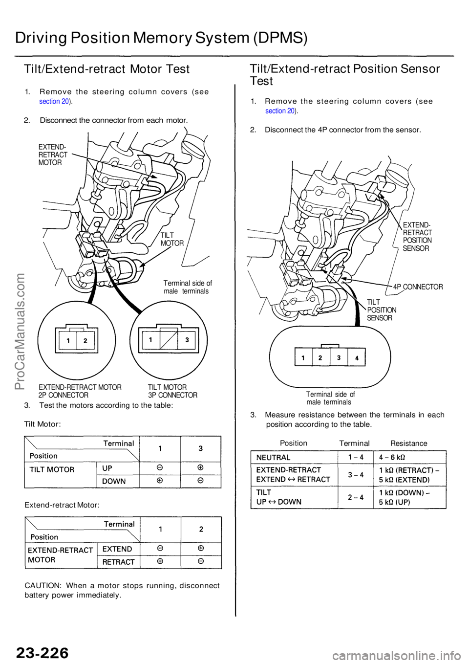
Tilt/Extend-retrac t Moto r Tes t
1. Remove the steering column covers (see
section 20 ).
2 . Disconnec t th e connecto r fro m eac h motor .
EXTEND -RETRAC TMOTOR
EXTEND-RETRAC T MOTO R TIL T MOTO R
2 P CONNECTO R 3 P CONNECTO R
3. Tes t th e motor s accordin g t o th e table :
Tilt Motor :
Extend-retrac t Motor :
CAUTION : Whe n a moto r stop s running , disconnec t
batter y powe r immediately .
Tilt/Extend-retrac t Positio n Senso r
Test
1. Remove the steering column covers (see
section 20 ).
2 . Disconnec t th e 4 P connecto r fro m th e sensor .
EXTEND -RETRAC TPOSITION
SENSO R
4 P CONNECTO R
Termina l sid e o f
mal e terminal s
3. Measur e resistanc e betwee n th e terminal s i n eac h
positio n accordin g t o th e table .
Positio nTermina lResistanc e
Terminal sid e o fmal e terminal s
TIL
T
MOTO R
TILT
POSITIO N
SENSO R
ProCarManuals.com
Page 1633 of 1954
Driving Positio n Memor y Syste m (DPMS )
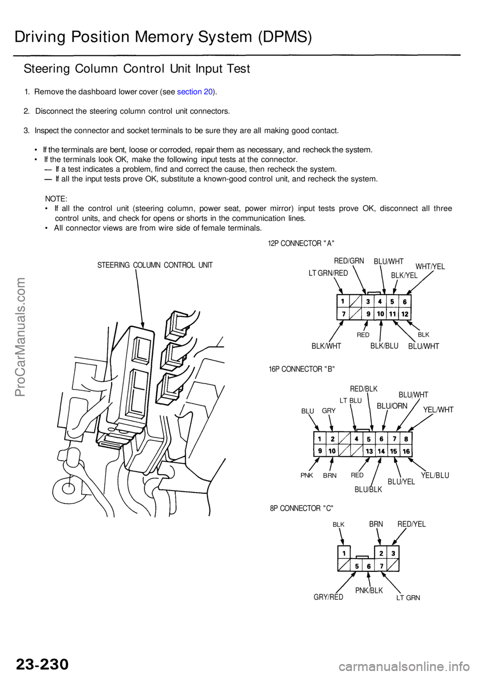
Steering Colum n Contro l Uni t Inpu t Tes t
1. Remov e th e dashboar d lowe r cove r (se e sectio n 20 ).
2 . Disconnec t th e steerin g colum n contro l uni t connectors .
3 . Inspec t th e connecto r an d socke t terminal s t o b e sur e the y ar e al l makin g goo d contact .
• I f th e terminal s ar e bent , loos e o r corroded , repai r the m as necessary , an d rechec k th e system .
• I f th e terminal s loo k OK , mak e th e followin g inpu t test s a t th e connector .
I f a tes t indicate s a problem , fin d an d correc t th e cause , the n rechec k th e system .
If al l th e inpu t test s prov e OK , substitut e a known-goo d contro l unit , an d rechec k th e system .
NOTE:
• I f al l th e contro l uni t (steerin g column , powe r seat , powe r mirror ) inpu t test s prov e OK , disconnec t al l thre e
contro l units , an d chec k fo r open s o r short s i n th e communicatio n lines .
• Al l connecto r view s ar e fro m wir e sid e o f femal e terminals .
STEERING COLUM N CONTRO L UNI T 12
P CONNECTO R "A "
BLK/WH T
BLK/BLUBLU/WH T
BLKRE D
WHT/YE L
RED/GR
N
BLU/WH T
BLK/YELLT GRN/RE D
16 P CONNECTO R "B "
BLUGR Y
LT BL U
RED/BL K
BLU/ORN
BLU/WH T
YEL/WHT
YEL/BLUBLU/YE LBLU/BLK
REDBR NPNK
8P CONNECTO R "C "
BLKBR N RED/YE L
LT GR NPNK/BL KGRY/RED
ProCarManuals.com
Page 1635 of 1954
Driving Positio n Memor y Syste m (DPMS )
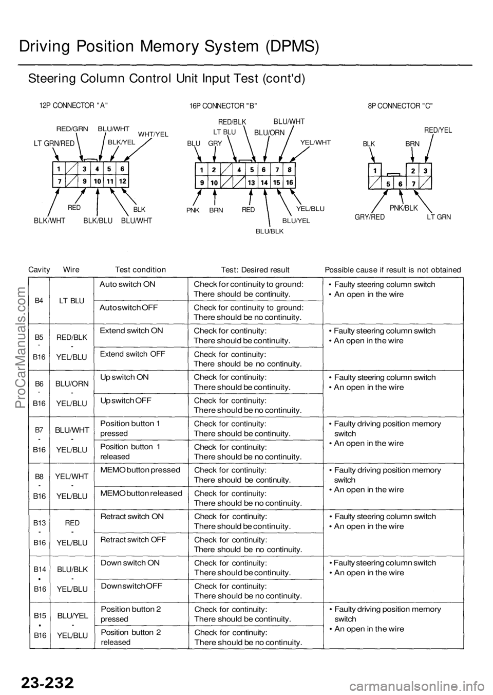
Steering Colum n Contro l Uni t Inpu t Tes t (cont'd )
12P CONNECTO R "A "
RED/GR N BLU/WH TWHT/YELBLK/YEL
PNK BR NREDYEL/BL U
BLU/YE L
BLU/BLK
8P CONNECTO R "C "
RED/YE L
BLKBR N
GRY/RE DLT GR N
Cavit y Wir eTest conditio nTest: Desire d resul tPossibl e caus e if resul t i s no t obtaine d
B4
B5*
B1 6
B6*
B1 6
B7•
B1 6
B8•
B1 6
B1 3•
B16
B1 4
B16
B15
B16
LT BL U
RED/BL K•
YEL/BLU
BLU/OR N•
YEL/BLU
BLU/WH T•
YEL/BLU
YEL/WH T•
YEL/BLU
RED•
YEL/BL U
BLU/BL K•
YEL/BL U
BLU/YEL•
YEL/BLU
Auto switc h O N
Aut o switc h OF F
Exten d switc h O N
Exten d switc h OF F
Up switc h O N
U p switc h OF F
Positio n butto n 1
presse d
Position butto n 1
release d
MEMO butto n presse d
MEM O butto n release d
Retrac t switc h O N
Retrac t switc h OF F
Dow n switc h O N
Dow n switc h OF F
Positio n butto n 2
presse d
Position butto n 2
release d
Check fo r continuit y to ground :
Ther e shoul d b e continuity .
Check fo r continuit y t o ground :
There shoul d b e n o continuity .
Chec k fo r continuity :
Ther e shoul d b e continuity .
Check fo r continuity :
There shoul d b e n o continuity .
Chec k fo r continuity :
Ther e shoul d b e continuity .
Check fo r continuity :
There shoul d b e n o continuity .
Check fo r continuity :
There shoul d b e continuity .
Chec k fo r continuity :
Ther e shoul d b e n o continuity .
Check fo r continuity :
There shoul d b e continuity .
Check fo r continuity :
There shoul d b e n o continuity .
Chec k fo r continuity :
Ther e shoul d b e continuity .
Check fo r continuity :
There shoul d b e n o continuity .
Check fo r continuity :
There shoul d b e continuity .
Check fo r continuity :
There shoul d b e n o continuity .
Check fo r continuity :
There shoul d b e continuity .
Chec k fo r continuity :
Ther e shoul d b e n o continuity .
• Fault y steerin g colum n switc h
• A n ope n in th e wir e
• Fault y steerin g colum n switc h
• A n ope n in th e wir e
• Fault y steerin g colum n switc h
• A n ope n in th e wir e
• Fault y drivin g positio n memor y
switch
• A n ope n in th e wir e
• Fault y drivin g positio n memor y
switc h
• A n ope n in th e wir e
• Fault y steerin g colum n switc h
• A n ope n in th e wir e
• Fault y steerin g colum n switc h
• A n ope n in th e wir e
• Fault y drivin g positio n memor y
switch
• A n ope n in th e wir e
16P CONNECTO R "B "
RED/BL K
BLU GR Y
LT BL UBLU/OR N
BLU/WH
T
YEL/WHT
PNK/BLK
BLK/WH T BLK/BL U BLU/WH TBLKRE D
LT GRN/RE D
ProCarManuals.com
Page 1636 of 1954
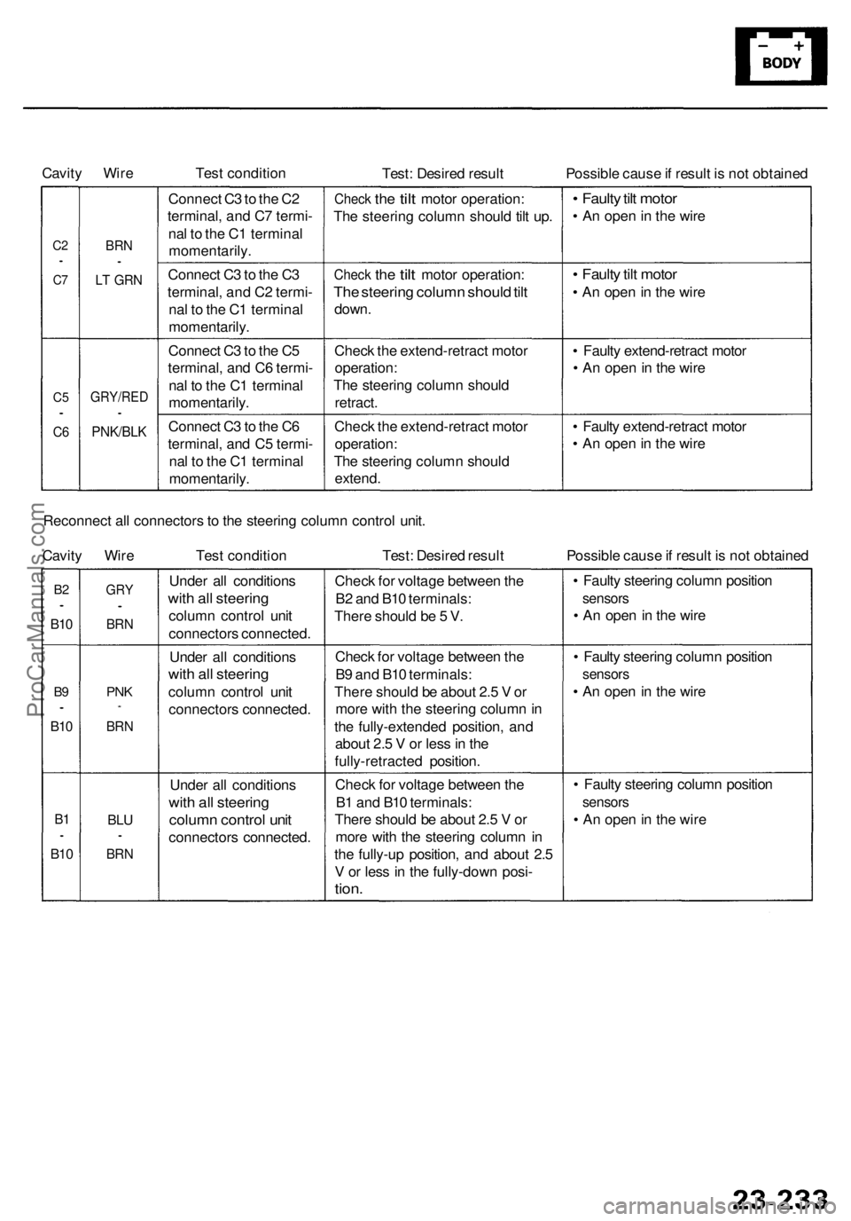
Cavity Wire
Test condition
Test: Desired result
Possible cause if result is not obtained
C2
•
C7
C5
•
C6
BRN
•
LT GRN
GRY/RED
•
PNK/BLK
Connect C3 to the C2
terminal, and C7 termi-
nal to the C1 terminal
momentarily.
Connect C3 to the C3
terminal, and C2 termi-
nal to the C1 terminal
momentarily.
Connect C3 to the C5
terminal, and C6 termi-
nal to the C1 terminal
momentarily.
Connect C3 to the C6
terminal, and C5 termi-
nal to the C1 terminal
momentarily.
Check
the
tilt
motor operation:
The steering column should tilt up.
Check
the
tilt
motor operation:
The steering column should tilt
down.
Check the extend-retract motor
operation:
The steering column should
retract.
Check the extend-retract motor
operation:
The steering column should
extend.
• Faulty tilt motor
• An open in the wire
• Faulty tilt motor
• An open in the wire
• Faulty extend-retract motor
• An open in the wire
• Faulty extend-retract motor
• An open in the wire
Reconnect all connectors to the steering column control unit.
Cavity Wire
Test condition
Test: Desired result
Possible cause if result is not obtained
B2
•
B10
B9
•
B10
B1
•
B10
GRY
•
BRN
PNK
*
BRN
BLU
•
BRN
Under all conditions
with all steering
column control unit
connectors connected.
Under all conditions
with all steering
column control unit
connectors connected.
Under all conditions
with all steering
column control unit
connectors connected.
Check for voltage between the
B2 and B10 terminals:
There should be 5 V.
Check for voltage between the
B9 and B10 terminals:
There should be about 2.5 V or
more with the steering column in
the fully-extended position, and
about 2.5 V or less in the
fully-retracted position.
Check for voltage between the
B1 and B10 terminals:
There should be about 2.5 V or
more with the steering column in
the fully-up position, and about 2.5
V or less in the fully-down posi-
tion.
• Faulty steering column position
sensors
• An open in the wire
• Faulty steering column position
sensors
• An open in the wire
• Faulty steering column position
sensors
• An open in the wireProCarManuals.com
Page 1803 of 1954
Precautions/Procedures
Steering-related Precaution s
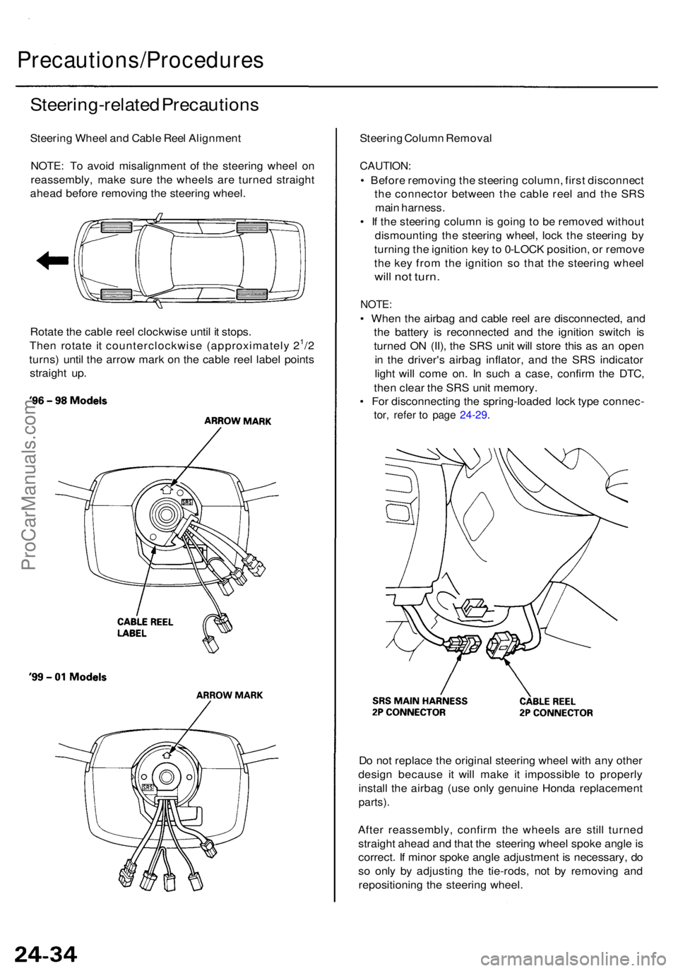
Steering Whee l an d Cabl e Ree l Alignmen t
NOTE : T o avoi d misalignmen t o f th e steerin g whee l o n
reassembly , mak e sur e th e wheel s ar e turne d straigh t
ahea d befor e removin g th e steerin g wheel .
Rotat e th e cabl e ree l clockwis e unti l i t stops .
The n rotat e i t counterclockwis e (approximatel y 2
1/2
turns ) unti l th e arro w mar k o n th e cabl e ree l labe l point s
straigh t up . Steerin
g Colum n Remova l
CAUTION :
• Befor e removin g th e steerin g column , firs t disconnec t
th e connecto r betwee n th e cabl e ree l an d th e SR S
mai n harness .
• I f th e steerin g colum n is goin g to b e remove d withou t
dismountin g th e steerin g wheel , loc k th e steerin g b y
turnin g th e ignitio n ke y to 0-LOC K position , o r remov e
th e ke y fro m th e ignitio n s o tha t th e steerin g whee l
will no t turn .
NOTE :
• Whe n th e airba g an d cabl e ree l ar e disconnected , an d
th e batter y i s reconnecte d an d th e ignitio n switc h i s
turne d O N (II) , th e SR S uni t wil l stor e thi s a s a n ope n
i n th e driver' s airba g inflator , an d th e SR S indicato r
ligh t wil l com e on . I n suc h a case , confir m th e DTC ,
the n clea r th e SR S uni t memory .
• Fo r disconnectin g th e spring-loade d loc k typ e connec -
tor, refe r t o pag e 24-29 .
Do no t replac e th e origina l steerin g whee l wit h an y othe r
desig n becaus e i t will mak e i t impossibl e t o properl y
instal l th e airba g (us e onl y genuin e Hond a replacemen t
parts).
After reassembly , confir m th e wheel s ar e stil l turne d
straigh t ahea d an d tha t th e steerin g whee l spok e angl e is
correct . I f mino r spok e angl e adjustmen t i s necessary , d o
s o onl y b y adjustin g th e tie-rods , no t b y removin g an d
repositionin g th e steerin g wheel .
ProCarManuals.com
Page 1933 of 1954
Airbag
Replacement (cont'd)
CAUTION: Be sure to install the SRS wiring so that it is
not pinched or interfering with other parts.
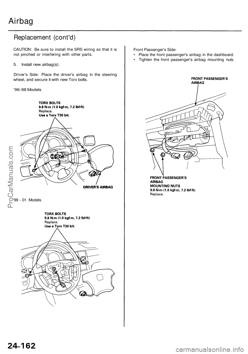
5. Install new airbag(s):
Driver's Side: Place the driver's airbag in the steering
wheel, and secure it with new Torx bolts.
'96-98 Models
Front Passenger's Side:
• Place the front passenger's airbag in the dashboard.
• Tighten the front passenger's airbag mounting nuts.
'99 - 01 ModelsProCarManuals.com