battery ACURA RL KA9 1996 Service Workshop Manual
[x] Cancel search | Manufacturer: ACURA, Model Year: 1996, Model line: RL KA9, Model: ACURA RL KA9 1996Pages: 1954, PDF Size: 61.44 MB
Page 1523 of 1954

Charg e unti l EY E show s charg e i s OK ; plu s a n
additiona l 3 0 minute s t o assur e ful l charge .
NOTE : I f th e batter y charg e i s ver y low , i t ma")
Charge o n Hig h Settin g (4 0 amps )
Charg e unti l EY E show s charg e i s OK ; plu s a n
additiona l 3 0 minute s t o assur e ful l charge .
NOTE : I f th e batter y charg e i s ver y low , i t ma y
b e necessar y t o bypas s th e charger' s polarit y
protectio n circuitry .
If th e EY E doe s no t sho w charg e i s O K withi n
3 hours , th e batter y i s no-good ; replac e it .
Writ e dow n ho w lon g th e batter y wa s
charged .
Test Loa d Capacit y (#2 )
• Appl y 30 0 am p loa d fo r 1 5 second s t o remov e surfac e charge .
• Allo w 1 5 second s recover y period .
• Appl y tes t loa d (se e Tes t Loa d Chart) .
• Recor d voltag e a t th e en d o f 1 5 seconds .
Stays abov e 9. 6 volts ; batter y is OK .Drop s belo w 9. 6 volts ; batter y is no-good .
BATTER Y COD E
80D26R-M F
TEST LOA D CHAR T
Us e th e tes t loa d o r 1/ 2 th e col d crankin g amp s (CCA ) printe d o n th e
labe l o n th e to p o f th e battery . I f neithe r i s indicated , us e th e
informatio n below :
BATTER Y
CODE
COLD CRANKIN G
AMPS (CCA )
LOAD
(amps )
27055 080
ProCarManuals.com
Page 1546 of 1954

CAUTION : Neve r tur n o n th e combinatio n ligh t switc h
befor e fittin g th e HI D bulb s t o thei r bul b socket s an")
Lighting Syste m
HID Lam p Syste m Troubleshootin g ('9 9 - 0 4 models )
CAUTION : Neve r tur n o n th e combinatio n ligh t switc h
befor e fittin g th e HI D bulb s t o thei r bul b socket s an d
completin g th e reassembl y o f th e headligh t assembly .
1 . Chec k th e No . 4 5 (2 0 A ) o r No . 4 6 (2 0 A ) fus e in th e
under-hoo d fuse/rela y box .
Are the fuses OK?
YES - G o to ste p 2 .
NO - Replac e th e fuse(s) , an d recheck .
2. Substitut e a known-goo d HI D bul b an d recheck .
Does the headlight low beam come on?
YES-Replac e th e HI D bulb .
N O - G o t o ste p 3 .
3 . Disconnec t th e 2 P connecto r fro m th e inverte r unit .
4. Tur n th e combinatio n ligh t switc h ON .
5. Measur e voltag e betwee n th e No . 2 termina l o f th e
inverte r uni t 2 P connecto r an d bod y ground .
INVERTE R UNI T 2 P CONNECTO R
Is there battery voltage?
YE S - G o to ste p 6 .
N O - Repai r ope n i n th e wir e betwee n th e under -
hoo d fuse/rela y bo x an d th e inverte r unit .
6 . Tur n th e combinatio n ligh t switc h OFF .
YES - Substitut e a known-goo d inverter , an d
recheck . I f th e symptom/indicatio n goe s away ,
replac e th e origina l inverte r unit .
NO - Replac e th e ignite r unit .
Is there about 1-2
7
. Chec k fo r continuit y betwee n th e No . 1 termina l o f
th e inverte r uni t 2 P connecto r an d bod y ground .
INVERTE R UNI T 2 P CONNECTE R
Is there continuity?
YE S - G o to ste p 8 .
N O - Repai r ope n i n th e wir e betwee n th e inverte r
unit an d bod y ground . I f th e wir e is OK , chec k fo r
poo r groun d a t G20 1 o r G301 .
8 . Measur e resistanc e betwee n th e No . 1 an d B termi -
nal an d th e No . 2 an d A termina l o f th e ignite r unit .
ProCarManuals.com
Page 1548 of 1954

A transien t hig h tensio n (25,00 0 V ) occur s
a t th e bul b socket s o f th e hig h intensit y discharg e (HID )
lamp s whe n th e combinati")
Headlights
HID Bul b Remova l ('9 9 - 0 4 models )
A transien t hig h tensio n (25,00 0 V ) occur s
a t th e bul b socket s o f th e hig h intensit y discharg e (HID )
lamp s whe n th e combinatio n ligh t switc h is turne d ON .
I t ma y caus e seriou s electrica l shoc k o r electrocutio n if
yo u d o no t observ e th e caution s below .
CAUTION :
• Neve r tur n o n th e combinatio n ligh t switc h befor e
fittin g th e HI D bulb s t o thei r bul b socket s an d com -
pletin g th e reassembl y o f th e headligh t assembly .
• T o preven t electrocution , d o no t servic e th e head -
light s assembl y i n we t conditions , suc h a s rai n o r
snow , nea r a sprinkle r system , o r whe n you r hand s
are wet .
• D o no t touc h th e surfac e o f th e HI D bulb s wit h you r
bar e hand s an d d o no t stai n i t wit h an y oil s an d
fats .
• D o no t disassembl e th e inverte r uni t an d th e ignite r
unit .
• D o no t tur n o n th e HI D bul b b y usin g a powe r
sourc e othe r tha n th e batter y mounte d o n you r
vehicle .
1. Mak e sur e yo u hav e th e anti-thef t cod e fo r th e radi o
an d th e navigatio n system , the n writ e dow n th e fre -
quencie s fo r th e radio' s prese t buttons .
2. Tur n th e combinatio n ligh t switc h OFF .
3. Disconnec t th e batter y negativ e cable , the n discon -
nec t th e positiv e cable .
4 . Remov e th e Tor x bol t (A ) usin g a Tor x T2 0 bit .
5 . Tur n th e cove r (B ) 45 ° counterclockwis e t o remov e
i t fro m th e headligh t assembly . 8
. Instal l th e ne w bul b in th e revers e orde r o f removal .
9. Afte r reconnectin g th e battery , ente r th e anti-thef t
code fo r th e radi o an d th e navigatio n system , the n
ente r th e customer' s radi o statio n presets .
BULB
SPRIN G
6. Tur n th e socke t 45 ° counterclockwis e t o remov e i t
fro m th e bulb .
BULB
7. Pul l th e retainin g sprin g awa y fro m th e bulb , the n
remov e th e bulb .
SOCKE T
ProCarManuals.com
Page 1583 of 1954

Close switch ON
Open switch (manual)
ON
RED/WHT
YEL
Auto open switch ON")
YEL/RED
Cavity Wire Test condition Test: Desired result Possible cause if result is not obtained
Ignition switch ON (II)
Close switch ON
Open switch (manual)
ON
RED/WHT
YEL
Auto open switch ON
Ignition switch ON (II)
YEL/GRN
or YEL
NOTE: The limit switches are switched in the moonroof positions as shown below:
Check for voltage to ground:
There should be battery voltage
with the limit switch 1 ON.
Check for voltage to ground:
There should be less than 2 V.
Check for voltage to ground:
There should be less than 2 V
with the limit switch 1 OFF,
and the limit switch 4 ON.
Check for voltage to ground:
There should be less than 3 V.
Check for voltage to ground:
There should be battery voltage.
• Faulty limit switch 1
• An open in the wire
• Poor ground
• Faulty moonroof switch
• An open in the wire
• Poor ground
• Faulty limit switch 1
• Faulty limit switch 4
• Faulty moonroof switch
• An open in the wire
• Poor ground
• Faulty moonroof switch
• An open in the wire
• An open in the wire
Tilt up Fully-closed Auto stop Fully-open
The moonroof stops automatically only when moving from open to closed when the limit switch 3 is turned ON.
Limit
switch 1
Limit
switch 2
Limit
switch 3
Limit
switch 4
ON
OFF
ON
OFF
ON
OFF
ON
OFFProCarManuals.com
Page 1654 of 1954
 Turn the ignition switch OFF.
2) Cancel the key-off operation timer in power window system by opening and closing one of the front doors.")
Confirming the Function
1. Shifting to the sleep mode:
1) Turn the ignition switch OFF.
2) Cancel the key-off operation timer in power window system by opening and closing one of the front doors.
3) Make sure that the trunk is closed, and exterior lights are off.
4) If you do not operate the switches related to the multiplex control units more than one minute after meeting the
above conditions, the system function shifts to the sleep mode.
(All of the switches must be turned OFF except door lock knob switches, ignition key switch, audio switch, and hood
switch.)
2. Confirming the sleep mode:
1) Check for voltage between the wake up line (PNK/BLU wire between driver's and passenger's control unit).
There should be no voltage with the sleep mode OFF.
There should be battery voltage with the sleep mode ON.
2) Check for voltage between each communication line and body ground while shifting to the sleep mode. There
should be no voltage.
3) Check the parasitic draw at the battery while shifting to the sleep mode. The ampere should change from 100 mA to
less than 100 mA.
3. Confirming the wake up mode:
After confirming the sleep mode, turn the related switch (see previous table) ON, and wake up each control unit. If all of
the operations works properly, the wake up mode is OK.
(If any of the control units are faulty and cannot wake up, several parts of the system will not work at the same time.)
Multiplex Control SystemProCarManuals.com
Page 1743 of 1954

Global Positionin g Syste m (GPS ) Limitation s
Th e GP S canno t detec t th e vehicl e positio n in thes e instances :
Fo r th e firs t 5 to 1 0 minute s")
Troubleshooting Precaution s (cont'd )
Global Positionin g Syste m (GPS ) Limitation s
Th e GP S canno t detec t th e vehicl e positio n in thes e instances :
Fo r th e firs t 5 to 1 0 minute s afte r reconnectin g th e battery .
Whe n th e satellit e signal s ar e blocke d b y tal l building , mountains , tunnels , larg e trees , o r larg e trucks .
Whe n th e GP S antenn a is blocke d b y somethin g o n th e packag e shelf .
Whe n ther e i s n o satellit e signa l output . (Signa l outpu t i s sometime s stoppe d fo r satellit e servicing. )
Whe n th e satellit e signal s ar e blocke d b y th e operatio n o f som e electroni c aftermarke t accessories .
Th e precisio n o f th e GP S is reduce d in thes e instances :
• Whe n onl y tw o satellit e signal s ca n b e received . (Thre e satellit e signal s ar e require d fo r accurat e positioning. )
• Whe n th e satellit e contro l cente r purposel y lower s th e signa l precision .
LC D Displa y Uni t Limitation s
• I n col d temperatures , th e displa y ma y sta y dar k fo r th e firs t 2 o r 3 minute s unti l i t warm s up .
• Whe n th e displa y i s to o ho t becaus e o f direc t summe r sunlight , i t wil l remai n dar k unti l th e temperatur e drops .
• Whe n th e humidit y i s hig h an d th e interio r temperatur e i s low , th e displa y ma y appea r cloudy . Th e displa y wil l clea r
afte r som e use .
• Fingerprint s o n th e touc h pane l ma y sometime s b e noticeabl e becaus e o f th e panel' s low-reflectio n coating . Whe n
cleanin g th e panel , wip e i t gentl y wit h a sof t cloth . T o avoi d scratchin g th e panel , d o no t ru b to o hard .
• Th e touc h pane l i s a n infrare d system , s o ther e is n o nee d t o pres s hard . I f a touc h switc h doe s no t functio n immediately ,
shif t you r finge r slightl y o n th e switch , an d touc h i t again .
Sympto m Duplicatio n
• Whe n th e sympto m ca n b e duplicated , follo w th e self-diagnosti c procedure s (pictur e diagnosi s mode ) an d th e appro -
priat e troubleshootin g procedures .
• Whe n th e sympto m doe s no t reappea r o r onl y reappear s intermittently , as k th e custome r abou t th e condition s whe n
th e sympto m occurred .
— Tr y t o establis h i f outsid e interferenc e ma y hav e bee n th e cause .
— Tr y t o duplicat e th e sympto m unde r th e sam e condition s th e custome r wa s experiencing .
— Vibration , temperatur e extremes , an d moistur e (dew , humidity ) ma y b e factor s tha t ar e difficul t t o duplicate .
Service Precaution s
• Befor e disconnectin g th e battery , mak e sur e yo u hav e th e anti-thef t code s fo r th e radi o an d th e navigatio n system , an d
writ e dow n th e frequencie s fo r th e radio' s prese t buttons .
• Afte r servicing , par k th e vehicl e i n a n are a wher e th e GP S satellit e signal s wil l b e unobstructed , an d chec k th e satellit e
mar k o n th e display .
• Whe n th e batter y i s disconnected , th e cloc k i s rese t t o "0:00. " Th e cloc k wil l rese t t o th e correc t tim e afte r th e syste m
receive s th e GP S satellit e signals .
• Afte r reconnectin g th e battery , yo u hav e t o wai t t o ge t a n initia l signa l fro m a satellite . Thi s take s abou t 1 0 minutes .
ProCarManuals.com
Page 1792 of 1954

Description
SRS Airbag System - '96 - 98 Models
The SRS is a safety device which, when used in conjunction with the seat belt, is designed to help protect the driver and
front passenger in a frontal impact exceeding a certain set limit. The system consists of the SRS unit (including safing sen-
sor and impact sensor), the cable reel, the driver's airbag, and front passenger's airbag.
Seat Belt Tensioner
The seat belt tensioner is linked with the SRS airbags to further increase the effectiveness of the seat belt. In a front-end
collision, the tensioner instantly retracts the belt firmly to secure the occupants in their seats.
Operation
The main circuit in the SRS unit senses and judges the force of impact and, if necessary, ignites the inflator charges. If battery
voltage is too low or power is disconnected due to the impact, the back-up power circuit will keep voltage at a constant level.
For the SRS to operate:
(1) The impact sensor and safing sensor must activate and send electric signals to the microprocessor.
(2) The microprocessor must compute the signals and send signals to the airbag inflators and seat belt tensioners.
(3) The inflators must ignite and deploy the airbags and activate the tensioners.
Self-diagnosis System
A self-diagnosis circuit is built into the SRS unit; when the ignition switch is turned ON (II), the SRS indicator light comes
on and goes off after about 6 seconds if the system is operating normally.
If the light does not come on, or does not go off after 6 seconds, or if it comes on while driving, it indicates an abnormality
in the system. The system must be inspected and repaired as soon as possible.
For better serviceability, the memory will store the cause of the malfunction, and the data link circuit passes on the infor-
mation from the memory to the data link connector (DLC). This information can be read with the Honda PGM Tester con-
nected to the DLC (16P).ProCarManuals.com
Page 1795 of 1954

Precautions/Procedures
General Precaution s
• Carefull y inspec t an y SR S par t befor e yo u instal l it . D o
no t instal l an y par t tha t show s sign s o f bein g droppe d
o r improperl y handled , suc h a s dents , crack s o r defor -
mation :
Airbag s (fronta l airbag s an d sid e airbags )
Cabl e ree l
SRS uni t
Sea t bel t tensioner s
• Us e onl y a digita l multimete r t o chec k th e system . I f
it' s no t a Hond a multimeter , mak e sur e it s outpu t i s
1 0 m A (0.0 1 A ) o r les s whe n switche d t o th e smalles t
valu e i n th e ohmmete r range . A teste r wit h a highe r
output coul d damag e th e airba g circui t o r caus e acci -
denta l deploymen t an d possibl e injury .
• D o no t instal l use d SR S part s fro m anothe r vehicle .
Whe n makin g SR S repairs , us e onl y ne w parts .
• Excep t whe n performin g electrica l inspections ,
alway s disconnec t bot h th e negativ e cabl e an d posi -
tive cabl e fro m th e battery , an d wai t a t leas t 3 min -
utes befor e beginnin g work .
• Replacemen t o f th e combinatio n ligh t an d wiper /
washe r switche s an d cruis e contro l switc h ca n b e
don e withou t removin g th e steerin g wheel :
For combinatio n ligh t an d wiper/washe r switc h
replacement , se e sectio n 23 .
Fo r cruis e contro l set/resume/cance l switc h
replacement , se e sectio n 4 .
• Wheneve r th e ignitio n switc h is O N (II) , o r ha s bee n
turne d OF F fo r les s tha n 3 minutes , b e carefu l no t t o
bum p th e SR S unit ; th e airbag s coul d accidentall y
deplo y an d caus e damag e o r injury .
• Wheneve r th e airbag s hav e bee n activated , replac e
th e sea t bel t tensioner s an d th e SR S unit .
• Th e origina l radi o ha s a code d thef t protectio n circuit .
B e sur e to ge t th e customer' s cod e numbe r befor e dis -
connectin g th e batter y cables .
• Th e PC M memor y mus t b e rese t afte r reconnectin g th e
batter y (se e pag e 11-125 ).
Airba g Handlin g an d Storag e
Do no t tr y t o disassembl e an y o f th e airbags , fronta l o r
side . The y hav e n o serviceabl e parts . Onc e a n airba g
ha s bee n operate d (deployed) , i t canno t b e repaire d o r
reused .
For temporar y storag e o f a n airba g durin g service ,
please observ e th e followin g precautions :
• Stor e a remove d airba g wit h th e pa d surfac e u p an d a
remove d sid e airba g wit h th e cautio n labe l surfac e up .
Al l airba g connector s hav e a built-i n shor t contac t (se e
page 24-30 ).
If a n airba g is improperl y store d fac e down ,
accidenta l deploymen t coul d prope l th e uni t wit h enoug h
forc e to caus e seriou s injury .
AIRBA G CONNECTOR S(With built-i n shor t contact )
• Stor e a remove d airba g o n a secur e fla t surfac e
awa y fro m an y hig h hea t sourc e (exceedin g
200°F/93°C ) an d fre e o f an y oil , grease , detergen t o r
water .
CAUTION : Imprope r handlin g o r storag e ca n internall y
damag e a n airbag , makin g it inoperative .
K yo u suspec t a n airba g ha s bee n damaged , instal l a ne w
unit , an d refe r t o th e Deployment/Disposa l Procedure s fo r
disposin g o f th e damage d airbag .
ProCarManuals.com
Page 1800 of 1954

Backprobing Spring-loade d Loc k
Connector s
• Whe n checkin g voltag e o r resistanc e o n thi s typ e o f
connecto r th e firs t time , i t i s necessar y t o remov e th e
retaine r t o inser t teste r probe s fro m th e wir e side .
NOTE : I t i s no t necessar y t o reinstal l th e remove d
retainer ; th e terminal s wil l sta y locke d i n th e connec -
to r housing .
Disconnectin g th e Airba g
Connector s an d Sea t Bel t
Tensione r Connector s
'9 6 - 9 8 Model s
Before removin g a n airba g o r othe r SR S relate d device s
(th e SR S uni t an d th e cabl e reel) , disconnectin g connec -
tor s fro m SR S relate d devices , o r removin g th e dash -
boar d o r th e steerin g column , disconnec t th e airba g
connector s t o preven t accidenta l deployment .
Tur n th e ignitio n switc h OF F an d disconnec t th e nega -
tiv e cabl e fro m th e battery , an d wai t a t leas t 3 minute s
befor e beginnin g th e followin g procedures .
• Befor e disconnectin g th e SR S mai n harnes s 18 P con -
necto r (A ) fro m th e SR S unit , disconnec t bot h airba g
2P connector s (C , D ) an d bot h sea t bel t tensione r 2 P
connector s (F , H) .
• Befor e disconnectin g th e cabl e ree l 2 P connecto r (B) ,
disconnec t th e driver' s airba g 2 P connecto r (C) .
• Befor e disconnectin g th e lef t sid e wir e harnes s 2 P
connecto r (E) , disconnec t th e driver' s sea t bel t ten -
sione r 2 P connector . (F) .
• Befor e disconnectin g th e righ t sid e wir e harnes s 2 P
connecto r (G) , disconnec t th e fron t passenge r sea t
bel t tensione r 2 P connecto r (H) .
Refe r t o pag e 24-3 3 fo r th e disconnec t th e connector(s) .
•
T o remov e th e retainer , inser t a fla t ti p screwdrive r
betwee n connecto r bod y an d retainer , an d carefull y
pr y ou t th e retainer .
NOTE : Tak e car e no t t o brea k th e connector .
ProCarManuals.com
Page 1801 of 1954
Refer t o pag e 24-3 3 fo r th e disconnec t th e connector(s) .
Precautions/Procedure s
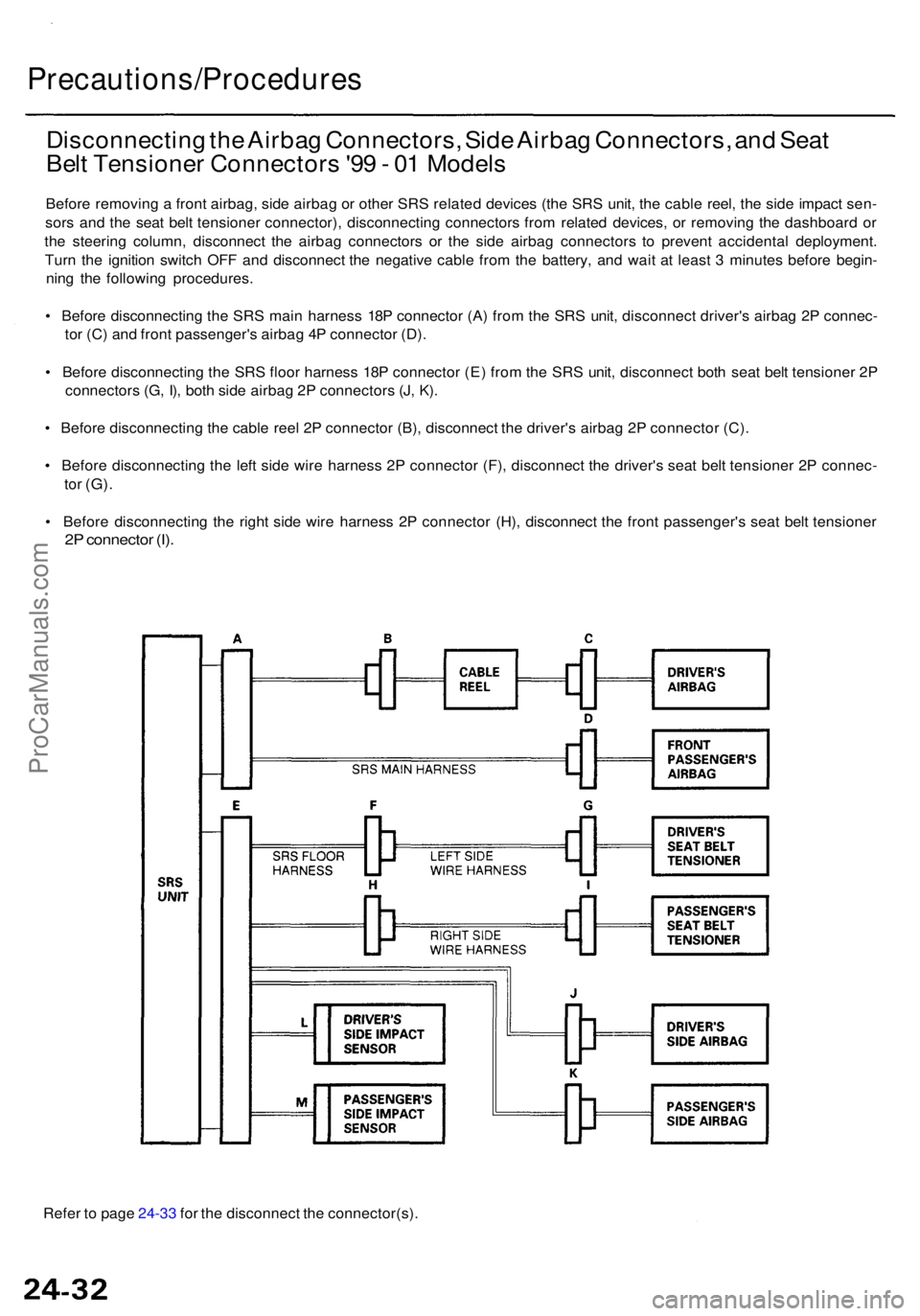
Disconnecting th e Airba g Connectors , Sid e Airba g Connectors , an d Sea t
Bel t Tensione r Connector s '9 9 - 0 1 Model s
Before removin g a fron t airbag , sid e airba g o r othe r SR S relate d device s (th e SR S unit , th e cabl e reel , th e sid e impac t sen -
sor s an d th e sea t bel t tensione r connector) , disconnectin g connector s fro m relate d devices , o r removin g th e dashboar d o r
th e steerin g column , disconnec t th e airba g connector s o r th e sid e airba g connector s t o preven t accidenta l deployment .
Tur n th e ignitio n switc h OF F an d disconnec t th e negativ e cabl e fro m th e battery , an d wai t a t leas t 3 minute s befor e begin -
nin g th e followin g procedures .
• Befor e disconnectin g th e SR S mai n harnes s 18 P connecto r (A ) fro m th e SR S unit , disconnec t driver' s airba g 2 P connec -
to r (C ) an d fron t passenger' s airba g 4 P connecto r (D) .
• Befor e disconnectin g th e SR S floo r harnes s 18 P connecto r (E ) fro m th e SR S unit , disconnec t bot h sea t bel t tensione r 2 P
connector s (G , I) , bot h sid e airba g 2 P connector s (J , K) .
• Befor e disconnectin g th e cabl e ree l 2 P connecto r (B) , disconnec t th e driver' s airba g 2 P connecto r (C) .
• Befor e disconnectin g th e lef t sid e wir e harnes s 2 P connecto r (F) , disconnec t th e driver' s sea t bel t tensione r 2 P connec -
tor (G) .
• Befor e disconnectin g th e righ t sid e wir e harnes s 2 P connecto r (H) , disconnec t th e fron t passenger' s sea t bel t tensione r
2P connecto r (I) .
ProCarManuals.com