relay ACURA RL KA9 1996 Service Manual PDF
[x] Cancel search | Manufacturer: ACURA, Model Year: 1996, Model line: RL KA9, Model: ACURA RL KA9 1996Pages: 1954, PDF Size: 61.44 MB
Page 1133 of 1954
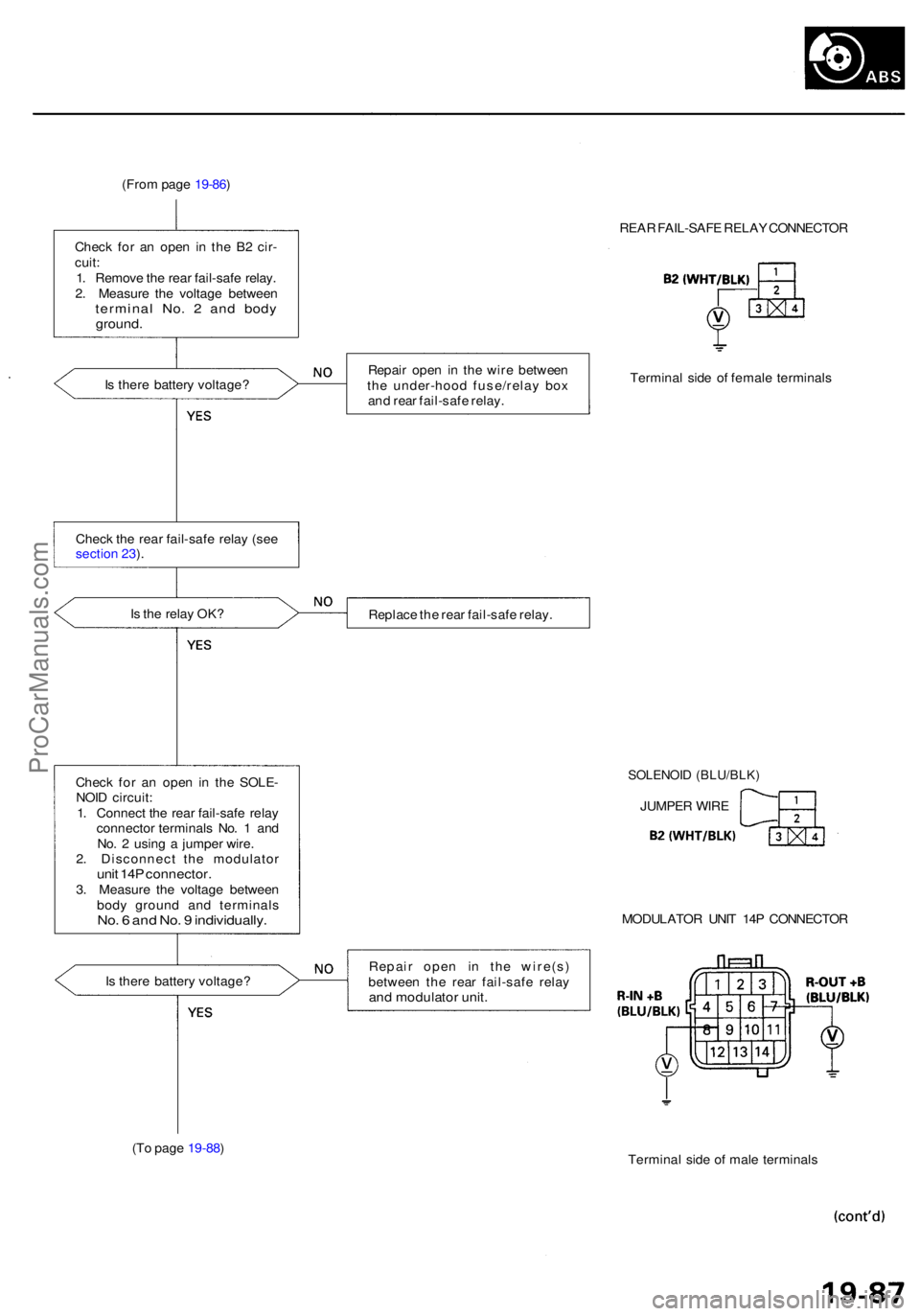
(From pag e 19-86 )
Chec k fo r a n ope n i n th e B 2 cir -
cuit :
1 . Remov e th e rea r fail-saf e relay .
2 . Measur e th e voltag e betwee n
termina l No . 2 an d bod yground .
REAR FAIL-SAF E RELA Y CONNECTO R
I s ther e batter y voltage ? Repai
r ope n i n th e wir e betwee n
th e under-hoo d fuse/rela y bo x
an d rea r fail-saf e relay . Termina
l sid e o f femal e terminal s
Chec k th e rea r fail-saf e rela y (se e
sectio n 23 ).
I s th e rela y OK ?
Replace th e rea r fail-saf e relay .
Chec k fo r a n ope n i n th e SOLE -
NOI D circuit :
1 . Connec t th e rea r fail-saf e rela y
connecto r terminal s No . 1 an d
No . 2 usin g a jumpe r wire .
2 . Disconnec t th e modulato r
unit 14 P connector .3. Measur e th e voltag e betwee n
bod y groun d an d terminal s
No. 6 an d No . 9 individually .
SOLENOID (BLU/BLK )
JUMPER WIR E
MODULATO R UNI T 14 P CONNECTO R
I s ther e batter y voltage ? Repai
r ope n i n th e wire(s )
betwee n th e rea r fail-saf e rela y
and modulato r unit .
(To pag e 19-88 )
Terminal sid e o f mal e terminal s
ProCarManuals.com
Page 1137 of 1954
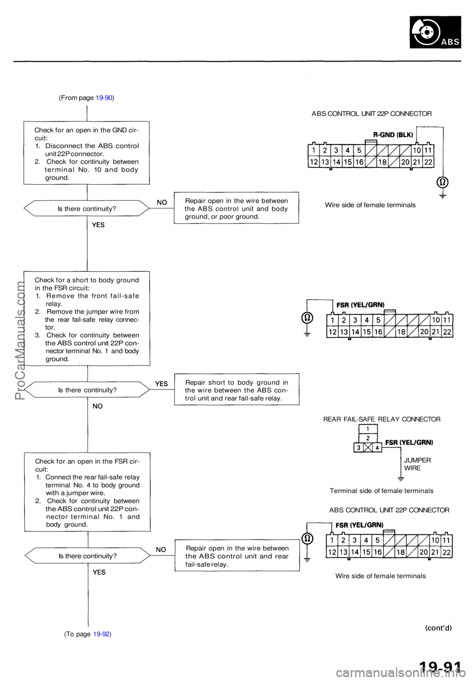
(From pag e 19-90 )
ABS CONTRO L UNI T 22 P CONNECTO R
Chec k fo r a n ope n in th e GN D cir -
cuit :1. Disconnec t th e AB S contro lunit 22 P connector .2. Chec k fo r continuit y betwee ntermina l No . 1 0 an d bod yground .
Is ther e continuity ? Repai
r ope n in th e wir e betwee n
th e AB S contro l uni t an d bod y
ground , o r poo r ground .Wire sid e o f femal e terminal s
Check fo r a shor t t o bod y groun d
i n th e FS R circuit :
1 . Remov e th e fron t fail-saf e
relay.2. Remov e th e jumpe r wir e fro m
th e rea r fail-saf e rela y connec -
tor.3. Chec k fo r continuit y betwee nthe AB S contro l uni t 22 P con -necto r termina l No . 1 an d bod yground .
Is ther e continuity ? Repai
r shor t t o bod y groun d i n
th e wir e betwee n th e AB S con -
tro l uni t an d rea r fail-saf e relay .
REAR FAIL-SAF E RELA Y CONNECTO R
Check fo r a n ope n in th e FS R cir -
cuit :
1 . Connec t th e rea r fail-saf e rela y
termina l No . 4 to bod y groun d
with a jumpe r wire .2. Chec k fo r continuit y betwee nthe AB S contro l uni t 22 P con -necto r termina l No . 1 an d
bod y ground . JUMPE
R
WIRE
Termina l sid e o f femal e terminal s
AB S CONTRO L UNI T 22 P CONNECTO R
Is ther e continuity ?Repair ope n in th e wir e betwee nthe AB S contro l uni t an d rea rfail-saf e relay .
Wire sid e o f femal e terminal s
(To pag e 19-92 )
ProCarManuals.com
Page 1151 of 1954
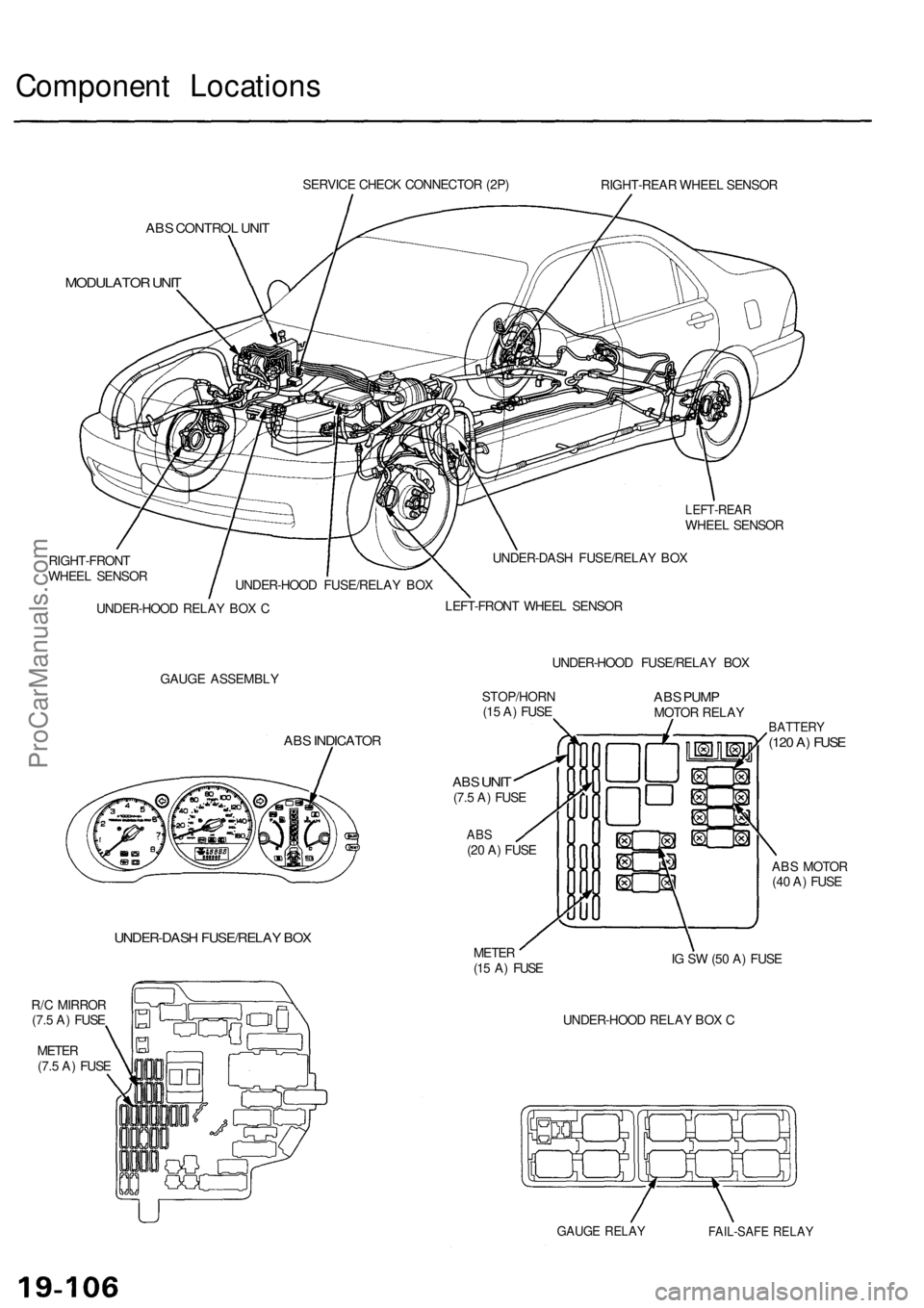
Component Locations
SERVICE CHECK CONNECTOR (2P)
RIGHT-REAR WHEEL SENSOR
ABS CONTROL UNIT
MODULATOR UNIT
LEFT-REAR
WHEEL SENSOR
RIGHT-FRONT
WHEEL SENSOR
UNDER-HOOD RELAY BOX C
UNDER-DASH FUSE/RELAY BOX
LEFT-FRONT WHEEL SENSOR
GAUGE ASSEMBLY
UNDER-HOOD FUSE/RELAY BOX
ABS INDICATOR
UNDER-DASH FUSE/RELAY BOX
R/C MIRROR
(7.5 A) FUSE
METER
(7.5 A) FUSE
STOP/HORN
(15 A) FUSE
ABS
UNIT
(7.5 A) FUSE
ABS
(20 A) FUSE
ABS PUMP
MOTOR RELAY
METER
(15 A) FUSE
BATTERY
(120 A) FUSE
ABS MOTOR
(40 A) FUSE
IG SW (50 A) FUSE
UNDER-HOOD RELAY BOX C
GAUGE RELAY
FAIL-SAFE RELAY
UNDER-HOOD FUSE/RELAY BOXProCarManuals.com
Page 1154 of 1954
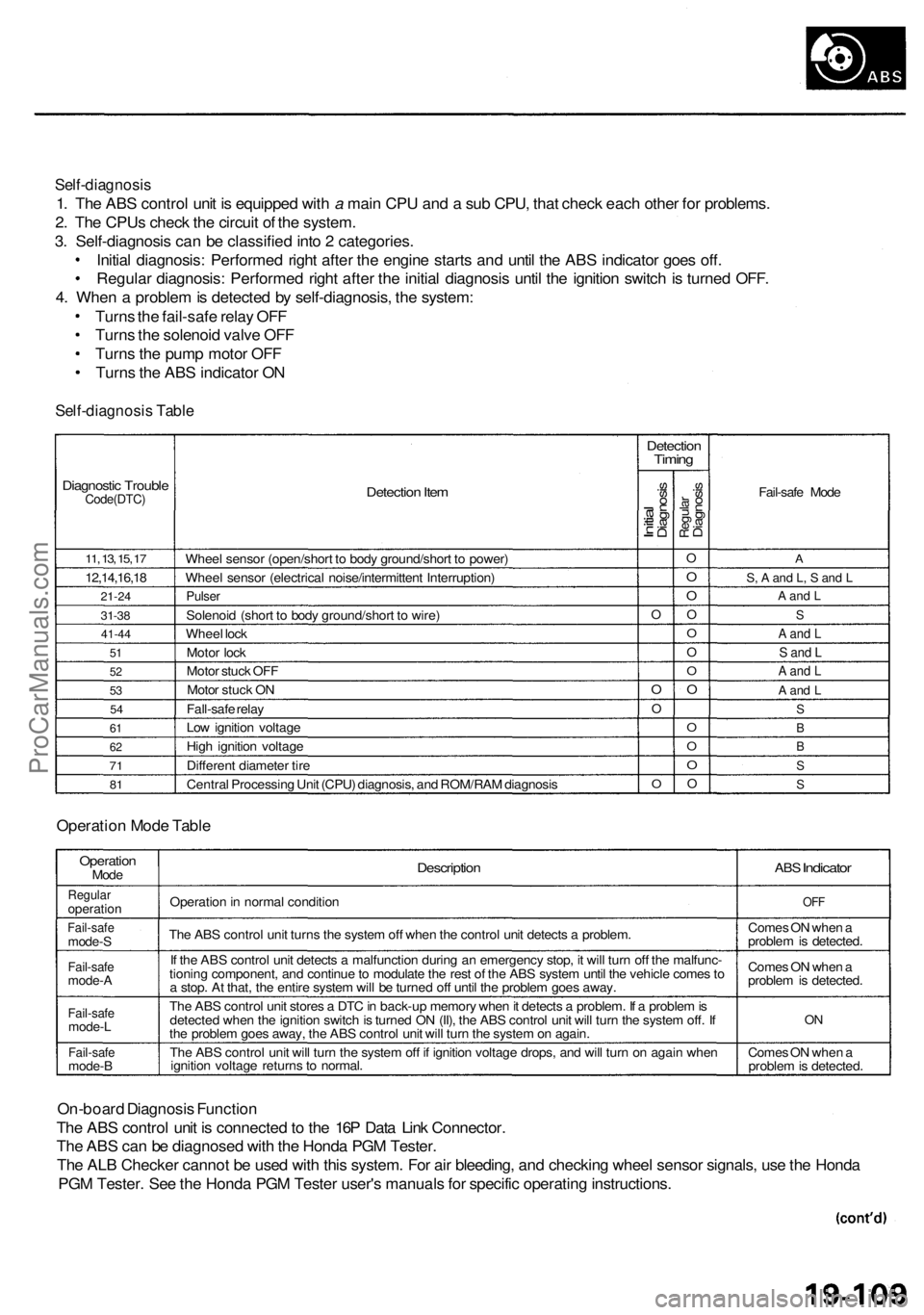
Self-diagnosis
1. The ABS control unit is equipped with a main CPU and a sub CPU, that check each other for problems.
2. The CPUs check the circuit of the system.
3. Self-diagnosis can be classified into 2 categories.
Initial diagnosis: Performed right after the engine starts and until the ABS indicator goes off.
Regular diagnosis: Performed right after the initial diagnosis until the ignition switch is turned OFF.
4. When a problem is detected by self-diagnosis, the system:
Turns the fail-safe relay OFF
Turns the solenoid valve OFF
Turns the pump motor OFF
Turns the ABS indicator ON
Self-diagnosis Table
Diagnostic Trouble
Code(DTC)
11, 13, 15, 17
12,14,16,18
21-24
31-38
41-44
51
52
53
54
61
62
71
81
Detection Item
Wheel sensor (open/short to body ground/short to power)
Wheel sensor (electrical noise/intermittent Interruption)
Pulser
Solenoid (short to body ground/short to wire)
Wheel lock
Motor lock
Motor stuck OFF
Motor stuck ON
Fall-safe relay
Low ignition voltage
High ignition voltage
Different diameter tire
Central Processing Unit (CPU) diagnosis, and ROM/RAM diagnosis
Detection
Timing
Initial
Diagnosis
O
O
O
O
Regular
Diagnosis
O
O
O
O
O
O
O
O
O
O
O
O
Fail-safe Mode
A
S, A and L, S and L
A and L
S
A and L
S and L
A and L
A and L
S
B
B
S
S
Operation Mode Table
Operation
Mode
Regular
operation
Fail-safe
mode-S
Fail-safe
mode-A
Fail-safe
mode-L
Fail-safe
mode-B
Description
Operation in normal condition
The ABS control unit turns the system off when the control unit detects a problem.
If the ABS control unit detects a malfunction during an emergency stop, it will turn off the malfunc-
tioning component, and continue to modulate the rest of the ABS system until the vehicle comes to
a stop. At that, the entire system will be turned off until the problem goes away.
The ABS control unit stores a DTC in back-up memory when it detects a problem. If a problem is
detected when the ignition switch is turned ON (II), the ABS control unit will turn the system off. If
the problem goes away, the ABS control unit will turn the system on again.
The ABS control unit will turn the system off if ignition voltage drops, and will turn on again when
ignition voltage returns to normal.
ABS
Indicator
OFF
Comes ON when a
problem is detected.
Comes ON when a
problem is detected.
ON
Comes ON when a
problem is detected.
On-board Diagnosis Function
The ABS control unit is connected to the 16P Data Link Connector.
The ABS can be diagnosed with the Honda PGM Tester.
The ALB Checker cannot be used with this system. For air bleeding, and checking wheel sensor signals, use the Honda
PGM Tester. See the Honda PGM Tester user's manuals for specific operating instructions.
ProCarManuals.com
Page 1158 of 1954
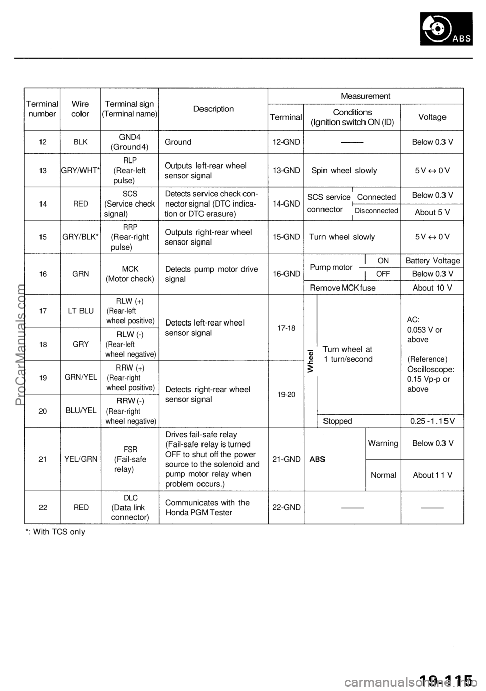
Terminal
number
12
13
1 4
15
16
17
1 8
19
2 0
2 1
2 2
Wir e
colo r
BLK
GRY/WHT *
RED
GRY/BLK *
GRN
LT BL U
GR Y
GRN/YE L
BLU/YEL
YEL/GR N
RED
Termina l sig n
(Termina l name )
GND4
(Groun d 4 )
RL P
(Rear-lef t
pulse)
SCS
(Servic e chec k
signal )
RRP
(Rear-righ t
pulse)
MCK
(Moto r check )
RLW (+ )
(Rear-lef t
wheel positive )
RLW (-)
(Rear-lef t
wheel negative )
RRW (+ )
(Rear-righ t
wheel positive )
RRW (-)
(Rear-righ t
wheel negative )
FSR
(Fail-saf e
relay)
DLC
(Dat a lin k
connector )
Description
Ground
Output s left-rea r whee l
senso r signa l
Detect s servic e chec k con -
necto r signa l (DT C indica -
tio n o r DT C erasure )
Output s right-rea r whee l
senso r signa l
Detect s pum p moto r driv e
signa l
Detect s left-rea r whee l
senso r signa l
Detect s right-rea r whee l
senso r signa l
Drive s fail-saf e rela y
(Fail-saf e rela y is turne d
OF F to shu t of f th e powe r
sourc e to th e solenoi d an d
pum p moto r rela y whe n
proble m occurs. )
Communicate s wit h th e
Hond a PG M Teste r
Measuremen t
Terminal
12-GND
13-GND
14-GN D
15-GND
16-GND
17-18
19-2 0
21-GN D
22-GN D
Condition s
(Ignition switch ON (ID )
Spi n whee l slowl y
SC S servic e Connecte d
connecto r
Disconnecte d
Turn whee l slowl y
ONPum p moto r —————OF F
Remov e MC K fus e
Tur n whee l a t
1 turn/secon d
Stoppe d
Warnin g
Norma l
Voltage
Below 0. 3 V
5 V 0 V
Below 0. 3 V
Abou t 5 V
5V 0 V
Batter y Voltag e
Belo w 0. 3 V
Abou t 1 0 V
AC :
0.05 3 V or
abov e
(Reference )
Oscilloscope :
0.15 Vp- p o r
abov e
0.25 -1.15 V
Below 0. 3 V
Abou t 1 1 V
* : Wit h TC S onl y
ProCarManuals.com
Page 1159 of 1954
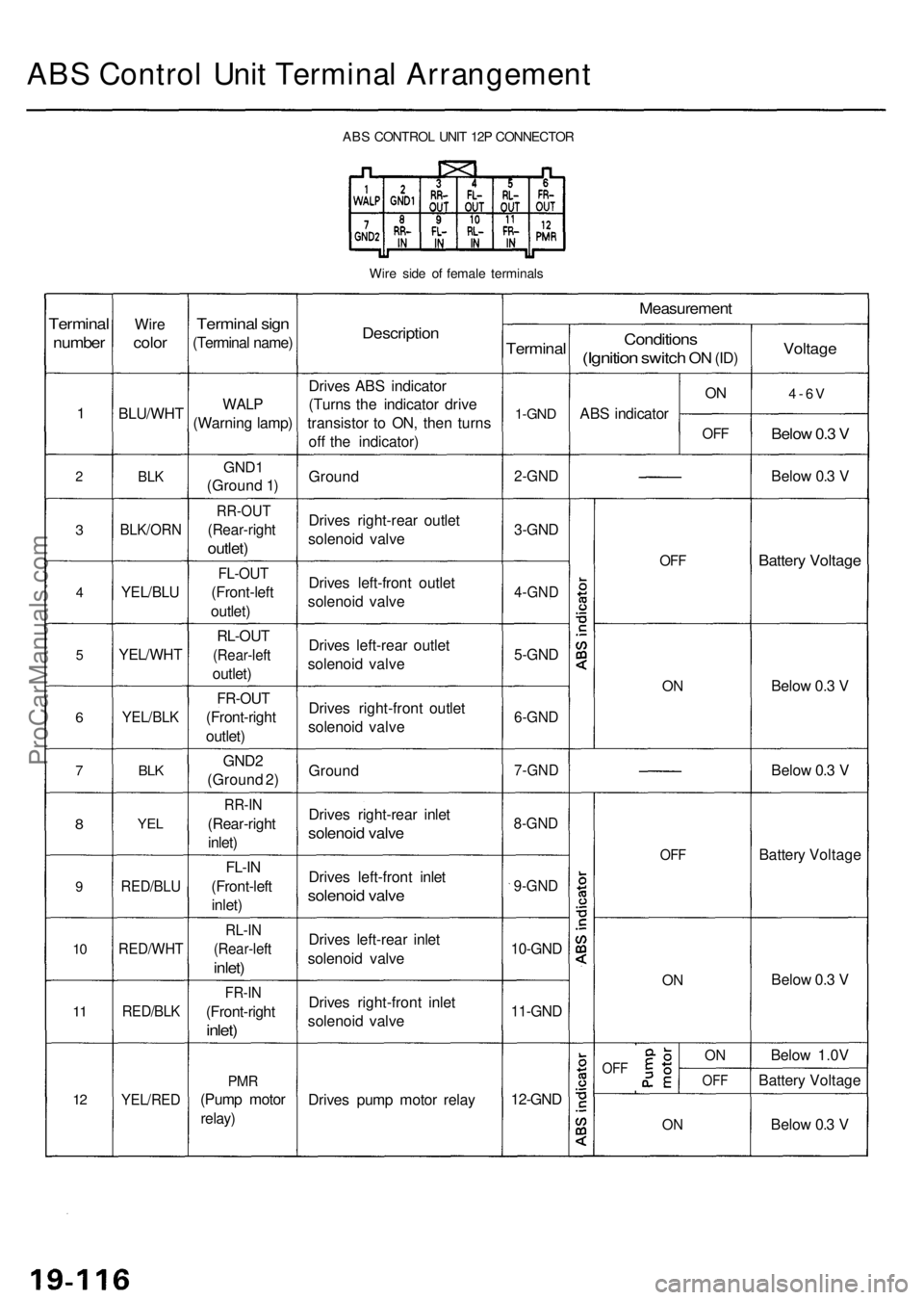
ABS Contro l Uni t Termina l Arrangemen t
ABS CONTRO L UNI T 12 P CONNECTO R
Wir e sid e o f femal e terminal s
Terminal
number
1
2
3
4
5
6
7
8
9
10
1 1
12
Wir e
colo r
BLU/WH T
BLK
BLK/OR N
YEL/BLU
YEL/WH T
YEL/BLK
BLK
YE L
RED/BL U
RED/WH T
RED/BLK
YEL/RE D
Terminal sig n
(Termina l name )
WALP
(Warnin g lamp )
GND1
(Groun d 1 )
RR-OU T
(Rear-righ t
outlet)
FL-OU T
(Front-lef t
outlet )
RL-OU T
(Rear-lef t
outlet)
FR-OU T
(Front-righ t
outlet )
GND 2
(Groun d 2 )
RR-I N
(Rear-righ t
inlet )
FL-I N
(Front-lef t
inlet )
RL-I N
(Rear-lef t
inlet)
FR-I N
(Front-righ t
inlet)
PMR
(Pum p moto r
relay)
Descriptio n
Drives AB S indicato r
(Turn s th e indicato r driv e
transisto r t o ON , the n turn s
of f th e indicator )
Groun d
Drive s right-rea r outle t
solenoi d valv e
Drive s left-fron t outle t
solenoi d valv e
Drive s left-rea r outle t
solenoi d valv e
Drive s right-fron t outle t
solenoi d valv e
Groun d
Drive s right-rea r inle t
solenoi d valv e
Drive s left-fron t inle t
solenoi d valv e
Drive s left-rea r inle t
solenoi d valv e
Drive s right-fron t inle t
solenoi d valv e
Drive s pum p moto r rela y
Measuremen t
Terminal
1-GND
2-GN D
3-GND
4-GN D
5-GND
6-GN D
7-GN D
8-GND
9-GND
10-GN D
11-GND
12-GND
Condition s
(Ignition switch ON (ID )
AB S indicato r
ON
OF F
OFF
ON
OF F
ON
OF FON
OF F
ON
Voltag e
4-6V
Below 0. 3 V
Belo w 0. 3 V
Batter y Voltag e
Below 0. 3 V
Belo w 0. 3 V
Batter y Voltag e
Belo w 0. 3 V
Belo w 1.0 V
Batter y Voltag e
Belo w 0. 3 V
ProCarManuals.com
Page 1160 of 1954
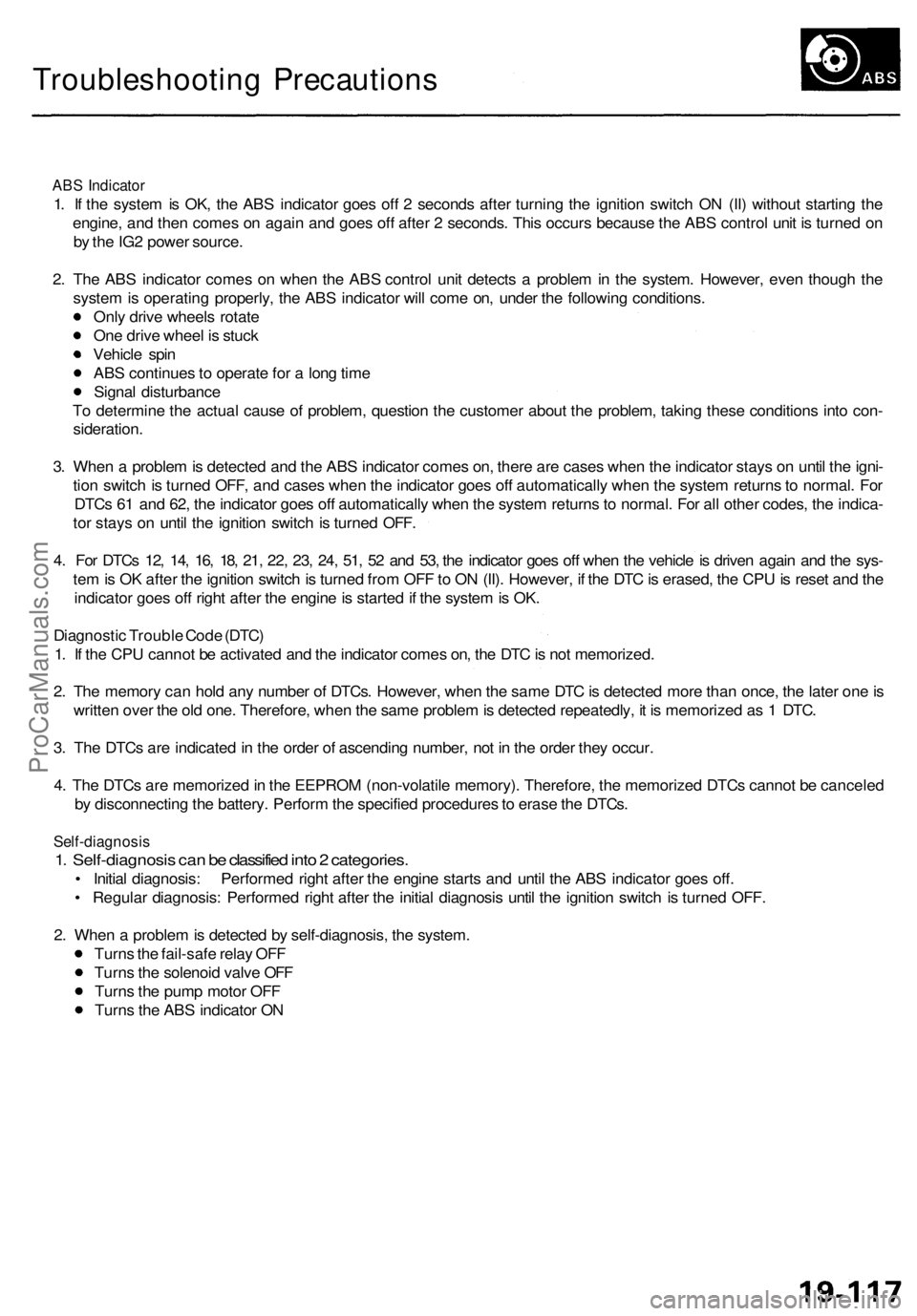
Troubleshooting Precautions
ABS Indicator
1. If the system is OK, the ABS indicator goes off 2 seconds after turning the ignition switch ON (II) without starting the
engine, and then comes on again and goes off after 2 seconds. This occurs because the ABS control unit is turned on
by the IG2 power source.
2. The ABS indicator comes on when the ABS control unit detects a problem in the system. However, even though the
system is operating properly, the ABS indicator will come on, under the following conditions.
Only drive wheels rotate
One drive wheel is stuck
Vehicle spin
ABS continues to operate for a long time
Signal disturbance
To determine the actual cause of problem, question the customer about the problem, taking these conditions into con-
sideration.
3. When a problem is detected and the ABS indicator comes on, there are cases when the indicator stays on until the igni-
tion switch is turned OFF, and cases when the indicator goes off automatically when the system returns to normal. For
DTCs 61 and 62, the indicator goes off automatically when the system returns to normal. For all other codes, the indica-
tor stays on until the ignition switch is turned OFF.
4. For DTCs 12, 14, 16, 18, 21, 22, 23, 24, 51, 52 and 53, the indicator goes off when the vehicle is driven again and the sys-
tem is OK after the ignition switch is turned from OFF to ON (II). However, if the DTC is erased, the CPU is reset and the
indicator goes off right after the engine is started if the system is OK.
Diagnostic Trouble Code (DTC)
1. If the CPU cannot be activated and the indicator comes on, the DTC is not memorized.
2. The memory can hold any number of DTCs. However, when the same DTC is detected more than once, the later one is
written over the old one. Therefore, when the same problem is detected repeatedly, it is memorized as 1 DTC.
3. The DTCs are indicated in the order of ascending number, not in the order they occur.
4. The DTCs are memorized in the EEPROM (non-volatile memory). Therefore, the memorized DTCs cannot be canceled
by disconnecting the battery. Perform the specified procedures to erase the DTCs.
Self-diagnosis
1. Self-diagnosis can be classified into 2 categories.
• Initial diagnosis: Performed right after the engine starts and until the ABS indicator goes off.
• Regular diagnosis: Performed right after the initial diagnosis until the ignition switch is turned OFF.
2. When a problem is detected by self-diagnosis, the system.
Turns the fail-safe relay OFF
Turns the solenoid valve OFF
Turns the pump motor OFF
Turns the ABS indicator ONProCarManuals.com
Page 1177 of 1954
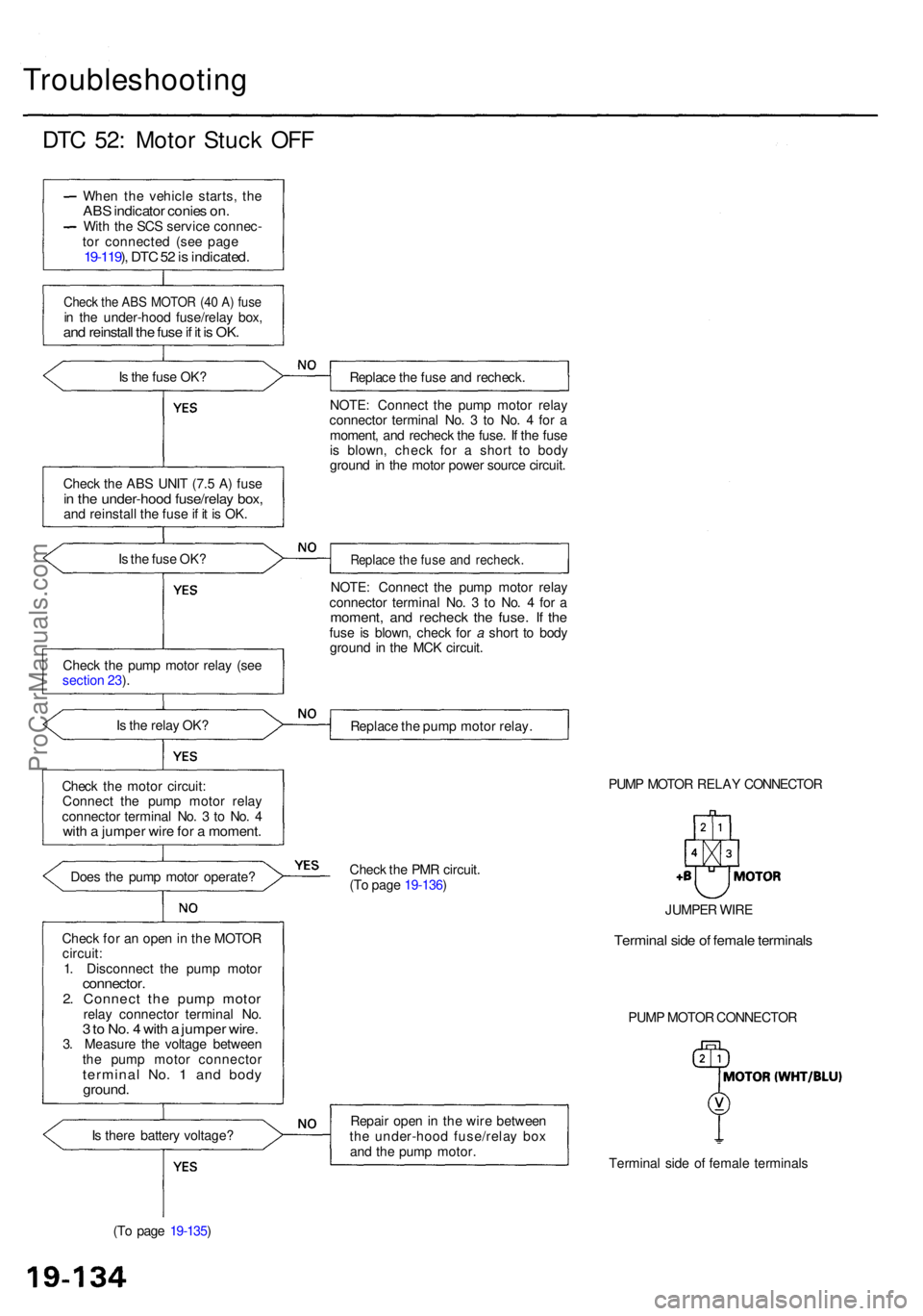
Troubleshooting
DTC 52 : Moto r Stuc k OF F
Whe n th e vehicl e starts , th eAB S indicato r conie s on .Wit h th e SC S servic e connec -
to r connecte d (se e pag e
19-119 ), DT C 52 is indicated .
Check th e AB S MOTO R (4 0 A ) fus ein th e under-hoo d fuse/rela y box ,and reinstal l th e fus e if i t i s OK .
Is th e fus e OK ?
Chec k th e AB S UNI T (7. 5 A ) fus e
in th e under-hoo d fuse/rela y box ,and reinstal l th e fus e if i t i s OK .
I s th e fus e OK ?
Chec k th e pum p moto r rela y (se e
sectio n 23 ).
I s th e rela y OK ?
Chec k th e moto r circuit :
Connec t th e pum p moto r rela y
connecto r termina l No . 3 to No . 4
wit h a jumpe r wir e fo r a moment .
Does th e pum p moto r operate ?
Chec k fo r a n ope n in th e MOTO R
circuit :
1 . Disconnec t th e pum p moto r
connector .2. Connec t th e pum p moto rrelay connecto r termina l No .3 to No . 4 wit h a jumpe r wire .3. Measur e th e voltag e betwee n
th e pum p moto r connecto r
terminal No . 1 an d bod yground .
Is ther e batter y voltage ?
(T o pag e 19-135 ) Replac
e th e fus e an d recheck .
NOTE : Connec t th e pum p moto r rela y
connecto r termina l No . 3 to No . 4 fo r a
moment , an d rechec k th e fuse . I f th e fus e
i s blown , chec k fo r a shor t t o bod y
groun d i n th e moto r powe r sourc e circuit .
Replac e th e fus e an d recheck .
NOTE: Connec t th e pum p moto r rela y
connecto r termina l No . 3 to No . 4 fo r a
moment , an d rechec k th e fuse . I f th efus e i s blown , chec k fo r a shor t t o bod y
groun d i n th e MC K circuit .
Replac e th e pum p moto r relay .
PUMP MOTO R RELA Y CONNECTO R
Chec k th e PM R circuit .
(T o pag e 19-136 )
Repai r ope n in th e wir e betwee n
th e under-hoo d fuse/rela y bo x
an d th e pum p motor .
Terminal sid e o f femal e terminal s
PUM
P MOTO R CONNECTO R
JUMPE
R WIR E
Termina l sid e o f femal e terminal s
ProCarManuals.com
Page 1180 of 1954
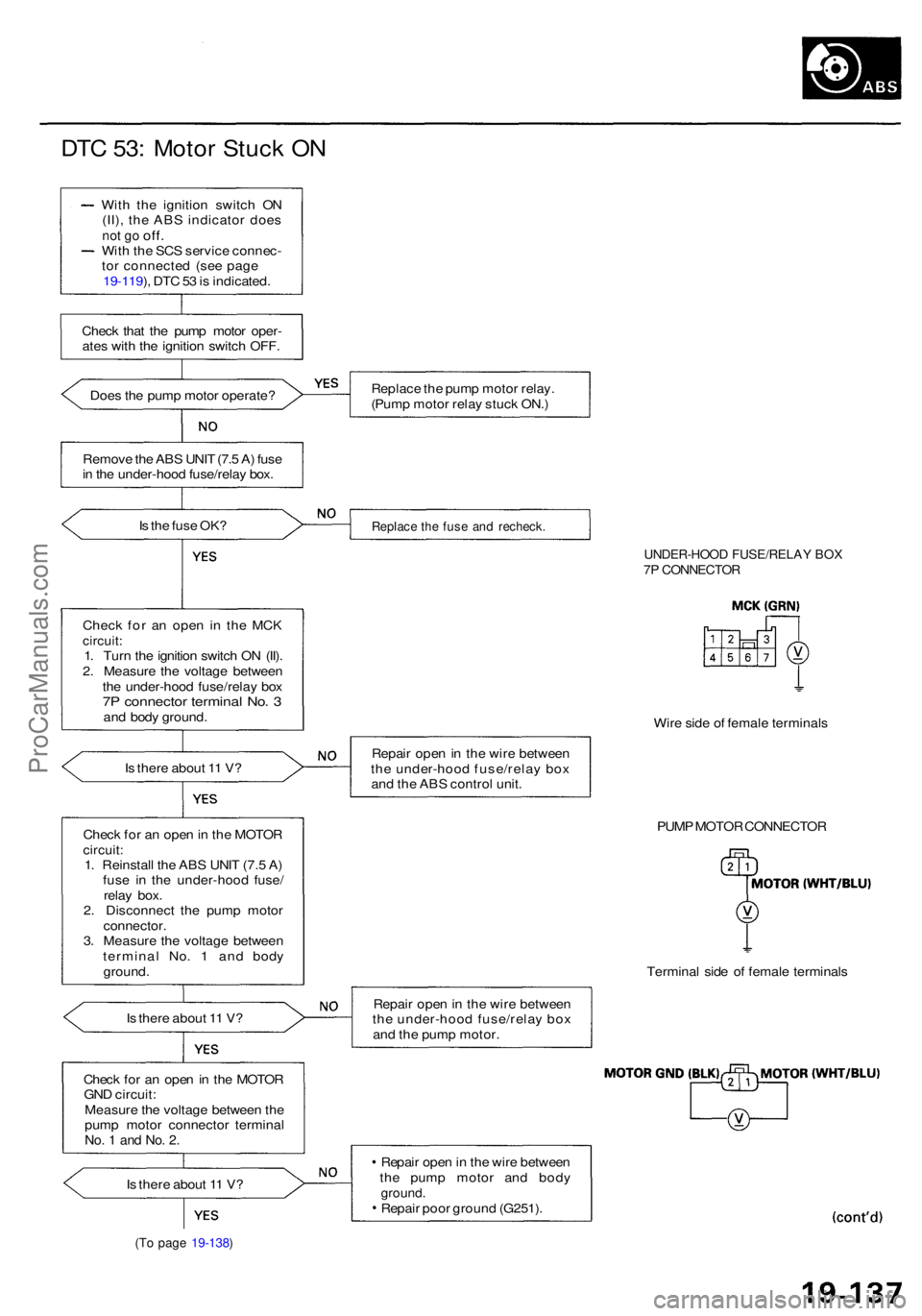
DTC 53 : Moto r Stuc k O N
Wit h th e ignitio n switc h O N
(II) , th e AB S indicato r doe s
not g o off .Wit h th e SC S servic e connec -
to r connecte d (se e pag e
19-119 ), DT C 53 is indicated .
Chec k tha t th e pum p moto r oper -
ate s wit h th e ignitio n switc h OFF .
Doe s th e pum p moto r operate ?
Remov e th e AB S UNI T (7. 5 A ) fus e
i n th e under-hoo d fuse/rela y box .
I s th e fus e OK ?
Chec k fo r a n ope n i n th e MC K
circuit :1. Tur n th e ignitio n switc h O N (II) .
2 . Measur e th e voltag e betwee n
th e under-hoo d fuse/rela y bo x
7P connecto r termina l No . 3an d bod y ground .
I s ther e abou t 1 1 V ?
Chec k fo r a n ope n in th e MOTO R
circuit:1. Reinstal l th e AB S UNI T (7. 5 A )
fus e i n th e under-hoo d fuse /
rela y box .
2 . Disconnec t th e pum p moto r
connector .3. Measur e th e voltag e betwee n
termina l No . 1 an d bod y
ground .
I s ther e abou t 1 1 V ?
Chec k fo r a n ope n in th e MOTO R
GN D circuit :
Measur e th e voltag e betwee n th e
pum p moto r connecto r termina l
No. 1 an d No . 2 .
Is ther e abou t 1 1 V ?
(To pag e 19-138 )
Replac e th e pum p moto r relay .
(Pum p moto r rela y stuc k ON. )
Replac e th e fus e an d recheck .
UNDER-HOO D FUSE/RELA Y BO X7P CONNECTO R
Wire sid e o f femal e terminal s
Repai r ope n in th e wir e betwee n
th e under-hoo d fuse/rela y bo x
an d th e AB S contro l unit .
PUMP MOTO R CONNECTO R
Termina l sid e o f femal e terminal s
Repai r ope n in th e wir e betwee n
th e under-hoo d fuse/rela y bo x
an d th e pum p motor .
Repai r ope n in th e wir e betwee n
th e pum p moto r an d bod y
ground .Repair poo r groun d (G251) .
ProCarManuals.com
Page 1181 of 1954
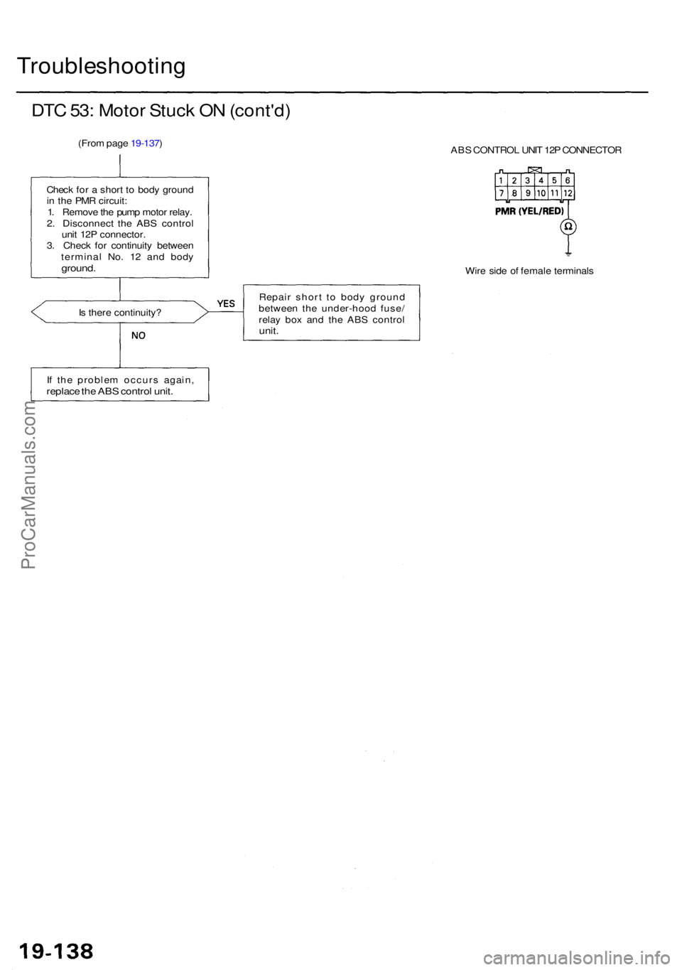
Troubleshooting
DTC 53 : Moto r Stuc k O N (cont'd )
(From pag e 19-137 )
ABS CONTRO L UNI T 12 P CONNECTO R
Chec k fo r a shor t t o bod y groun d
i n th e PM R circuit :
1 . Remov e th e pum p moto r relay .
2 . Disconnec t th e AB S contro l
uni t 12 P connector .
3 . Chec k fo r continuit y betwee n
termina l No . 1 2 an d bod y
ground .Wire sid e o f femal e terminal s
I s ther e continuity ? Repai
r shor t t o bod y groun d
betwee n th e under-hoo d fuse /
rela y bo x an d th e AB S contro l
unit.
If th e proble m occur s again ,replace th e AB S contro l unit .
ProCarManuals.com