brake ACURA RL KA9 1996 Service Repair Manual
[x] Cancel search | Manufacturer: ACURA, Model Year: 1996, Model line: RL KA9, Model: ACURA RL KA9 1996Pages: 1954, PDF Size: 61.44 MB
Page 1 of 1954
General Info
Specifications
Maintenance
*Engine Electrical
Engine
Cooling
Fuel and Emissions
*TransaxleSteering
Suspension
*Brakes (Including ABS,
TCS and VSA)
*Body
*Heating, Ventilation and Air Conditioning
*Body Electrical
*Restraints
1996±0 4 3.5RL Main Menu
As sections w/ * include SRS components,
special precautions are required when servicing.
ProCarManuals.com
Page 9 of 1954
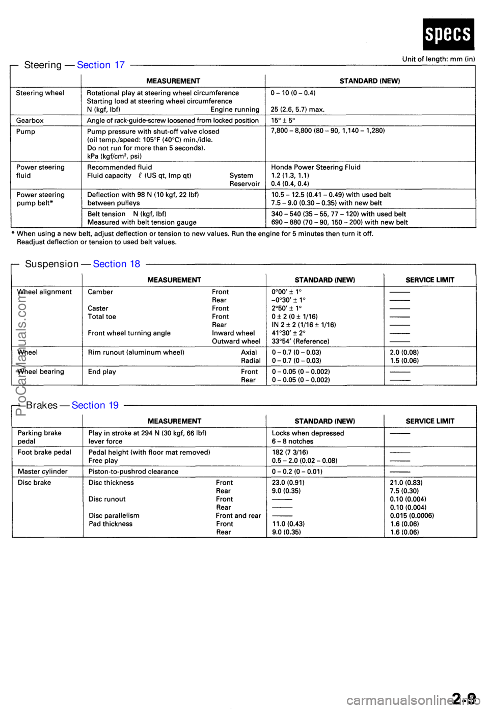
Steering — Sectio n 1 7
Suspensio n — Sectio n 1 8
Brake s — Sectio n 1 9
ProCarManuals.com
Page 70 of 1954
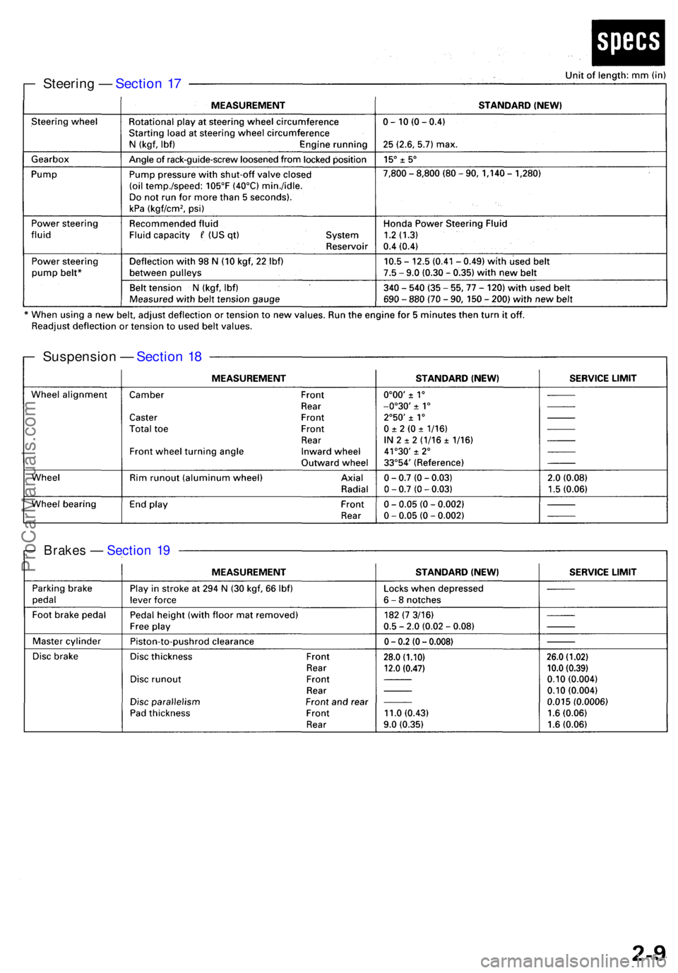
Steering — Sectio n 1 7
Suspensio n — Sectio n 1 8
Brake s — Sectio n 1 9
ProCarManuals.com
Page 96 of 1954
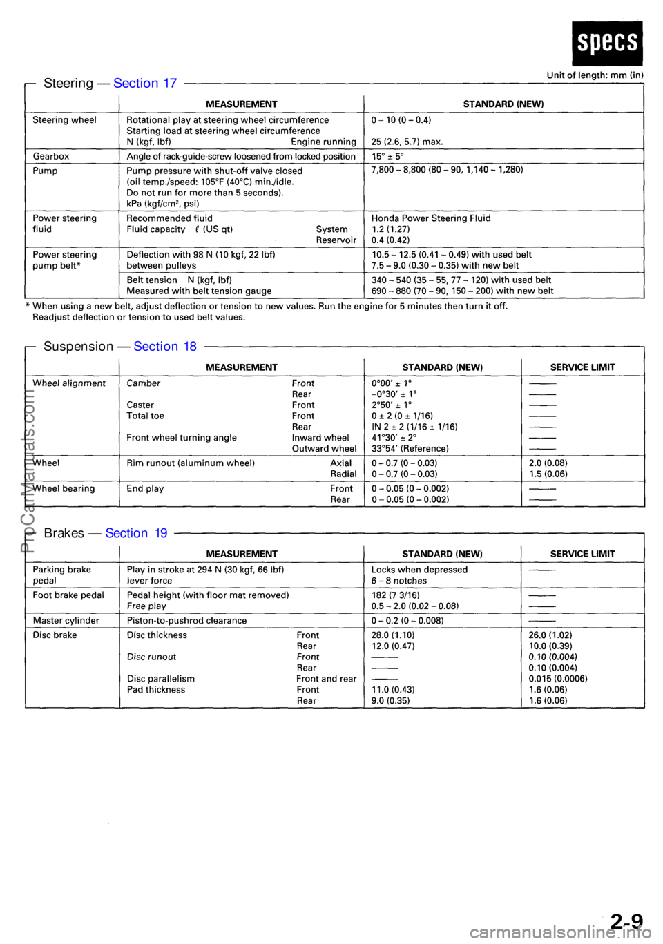
Brakes — Sectio n 1 9
Suspensio
n — Sectio n 1 8
Steerin g — Sectio n 1 7
ProCarManuals.com
Page 132 of 1954
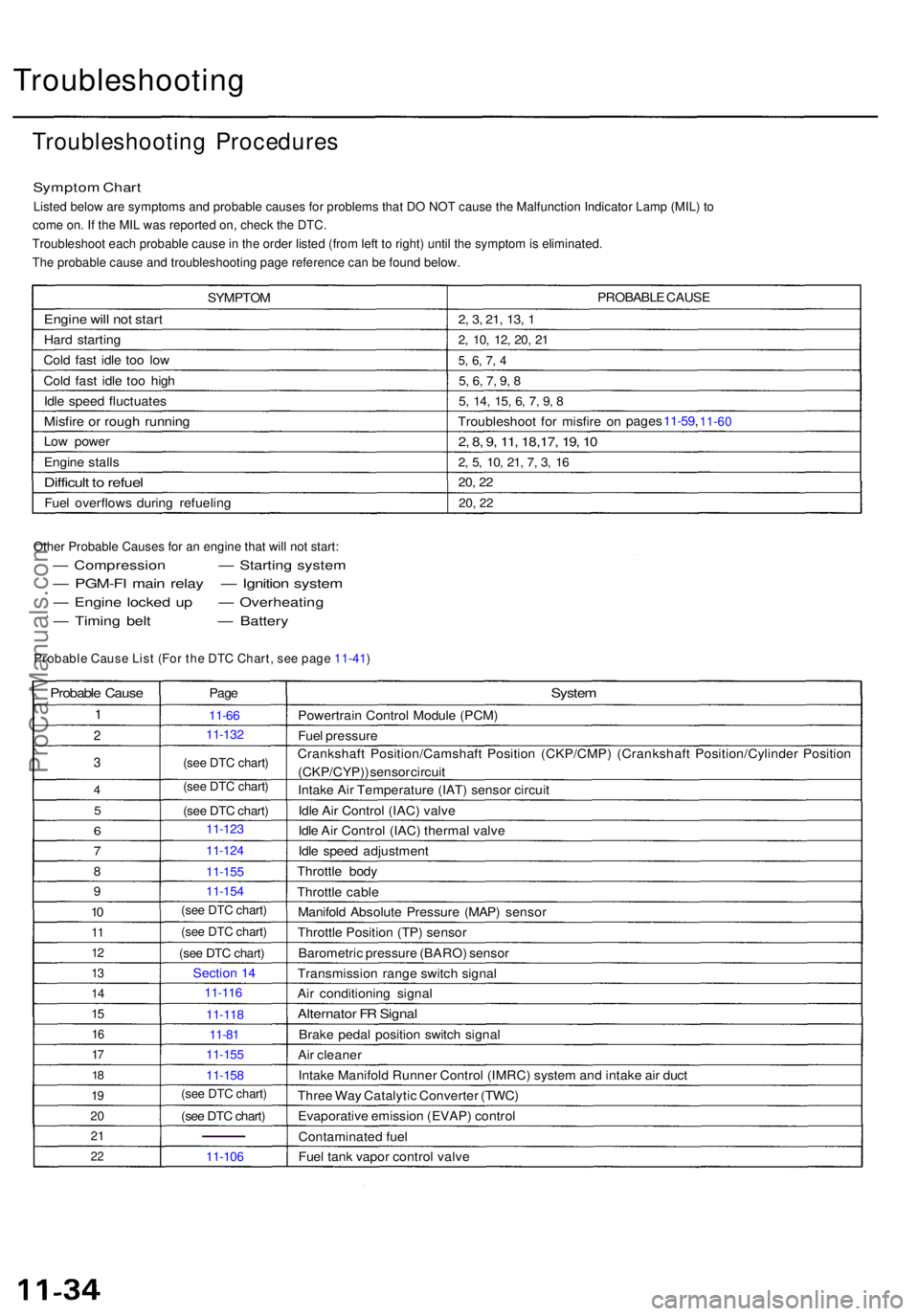
Troubleshooting
Troubleshooting Procedure s
Symptom Char t
Listed below are symptoms and probable causes for problems that DO NOT cause the Malfunction Indicator Lamp (MIL) to
come on. If the MIL was reported on, check the DTC.
Troubleshoot each probable cause in the order listed (from left to right) until the symptom is eliminated.
The probable cause and troubleshooting page reference can be found below.
SYMPTO M
Engine wil l no t star t
Hard startin g
Col d fas t idl e to o lo w
Col d fas t idl e to o hig h
Idl e spee d fluctuate s
Misfire o r roug h runnin g
Low powe r
Engin e stall s
Difficul t t o refue l
Fuel overflow s durin g refuelin g PROBABL
E CAUS E
2, 3 , 21 , 13 , 1
2 , 10 , 12 , 20 , 2 1
5, 6 , 7 , 4
5 , 6 , 7 , 9 , 8
5 , 14 , 15 , 6 , 7 , 9 , 8
Troubleshoo t fo r misfir e o n page
s 11-59 , 11-60
2 , 8 , 9 , 11 , 18,17 , 19 , 1 0
2, 5 , 10 , 21 , 7 , 3 , 1 6
20 , 2 2
20 , 2 2
Other Probable Causes for an engine that will not start:
— Compressio n — Starting syste m
— PGM-F I mai n rela y — Ignitio n syste m
— Engin e locke d u p — Overheatin g
— Timin g bel t — Battery
Probable Caus e
1
2
3
4
5
6
7
8
9
10
1 1
1 2
13
1 4
15
1 6
17
1 8
1 9
2 0
2 1
22
Pag e
11-6 6
(see DTC chart)
(see DTC chart)
(see DTC chart)
Sectio n 1 4
11-8 1
(see DTC chart)
11-10 6
System
Powertrai n Contro l Modul e (PCM )
Fue l pressur e
Crankshaf t Position/Camshaf t Positio n (CKP/CMP ) (Crankshaf t Position/Cylinde r Positio n
(CKP/CYP) ) senso r circui t
Intak e Ai r Temperatur e (IAT ) senso r circui t
Idl e Ai r Contro l (IAC ) valv e
Idl e Ai r Contro l (IAC ) therma l valv e
Idl e spee d adjustmen t
Throttl e bod y
Throttl e cabl e
Manifol d Absolut e Pressur e (MAP ) senso r
Throttl e Positio n (TP ) senso r
Barometri c pressur e (BARO ) senso r
Transmissio n rang e switc h signa l
Ai r conditionin g signa l
Alternato r F R Signa l
Brake peda l positio n switc h signa l
Ai r cleane r
Intak e Manifol d Runne r Contro l (IMRC ) syste m an d intak e ai r duc t
Thre e Wa y Catalyti c Converte r (TWC )
Evaporativ e emissio n (EVAP ) contro l
Contaminate d fue l
Fue l tan k vapo r contro l valv e
Probable Cause List (For the DTC Chart, see page 11-41)
(see DTC chart)
(see DTC chart)
(see DTC chart)
(see DTC chart)
11- 132
11- 123
11- 124
11- 155
11- 154
11- 116
11- 118
11- 155
11- 158
ProCarManuals.com
Page 171 of 1954
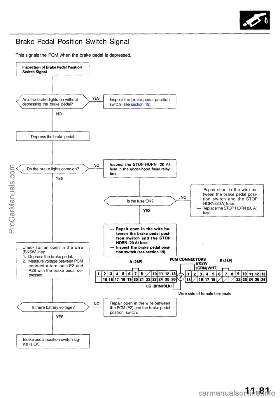
Brake Peda l Positio n Switc h Signa l
This signal s th e PC M whe n th e brak e peda l i s depressed .
Are th e brak e light s o n withou t
depressin g th e brak e pedal ? Inspec
t th e brak e peda l positio n
switc h (se e sectio n 19) .
NO
Depres s th e brak e pedal .
D o th e brak e light s com e on ?
YES
Is th e fus e OK ?
Chec k fo r a n ope n i n th e wir e
(BKS W line) :
1 . Depres s th e brak e pedal .
2 . Measur e voltag e betwee n PC M
connecto r terminal s E 2 an d
A2 6 wit h th e brak e peda l de -
pressed . —
Repai r shor t i n th e wir e be -
twee n th e brak e peda l posi -
tio n switc h an d th e STO P
HOR N (2 0 A ) fuse .
— Replac e th e STO P HOR N (2 0 A )
fuse .
Is ther e batter y voltage ? Repai
r ope n in th e wir e betwee n
th e PC M (E2 ) an d th e brak e peda l
positio n switch .
Brak e peda l positio n switc h sig -
nal i s OK .
ProCarManuals.com
Page 298 of 1954
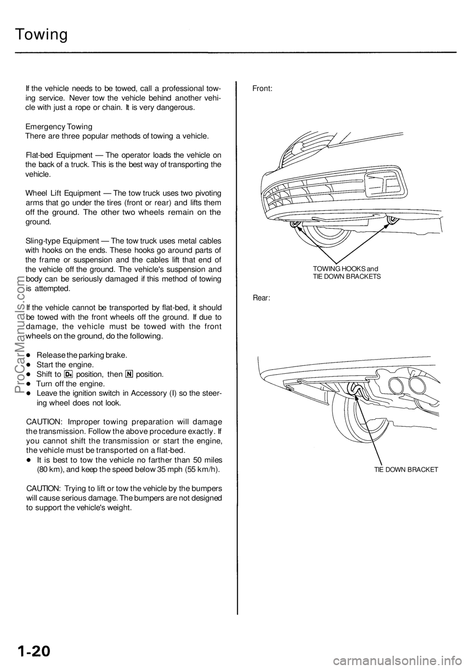
Towing
If th e vehicl e need s t o b e towed , cal l a professiona l tow -
in g service . Neve r to w th e vehicl e behin d anothe r vehi -
cl e wit h jus t a rop e o r chain . I t i s ver y dangerous .
Emergenc y Towin g
Ther e ar e thre e popula r method s o f towin g a vehicle .
Flat-be d Equipmen t — Th e operato r load s th e vehicl e o n
th e bac k o f a truck . Thi s is th e bes t wa y o f transportin g th e
vehicle .
Whee l Lif t Equipmen t — Th e to w truc k use s tw o pivotin g
arm s tha t g o unde r th e tire s (fron t o r rear ) an d lift s the m
off th e ground . Th e othe r tw o wheel s remai n o n th e
ground .
Sling-typ e Equipmen t — Th e to w truc k use s meta l cable s
wit h hook s o n th e ends . Thes e hook s g o aroun d part s o f
th e fram e o r suspensio n an d th e cable s lif t tha t en d o f
th e vehicl e of f th e ground . Th e vehicle' s suspensio n an d
bod y ca n b e seriousl y damage d i f thi s metho d o f towin g
i s attempted .
I f th e vehicl e canno t b e transporte d b y flat-bed , i t shoul d
b e towe d wit h th e fron t wheel s of f th e ground . I f du e t o
damage , th e vehicl e mus t b e towe d wit h th e fron t
wheel s o n th e ground , d o th e following .
Release th e parkin g brake .
Star t th e engine .
Shift t o position , the n position .
Tur n of f th e engine .
Leav e th e ignitio n switc h in Accessor y (I ) s o th e steer -
in g whee l doe s no t look .
CAUTION : Imprope r towin g preparatio n wil l damag e
th e transmission . Follo w th e abov e procedur e exactly . I f
yo u canno t shif t th e transmissio n o r star t th e engine ,
th e vehicl e mus t b e transporte d o n a flat-bed .
I t i s bes t t o to w th e vehicl e n o farthe r tha n 5 0 mile s
(8 0 km) , an d kee p th e spee d belo w 35 mp h (5 5 km/h) .
CAUTION : Tryin g to lif t o r to w th e vehicl e b y th e bumper s
wil l caus e seriou s damage . Th e bumper s ar e no t designe d
t o suppor t th e vehicle' s weight .
Front:
TOWIN G HOOK S an dTIE DOW N BRACKET S
Rear:
TIE DOW N BRACKE T
ProCarManuals.com
Page 304 of 1954
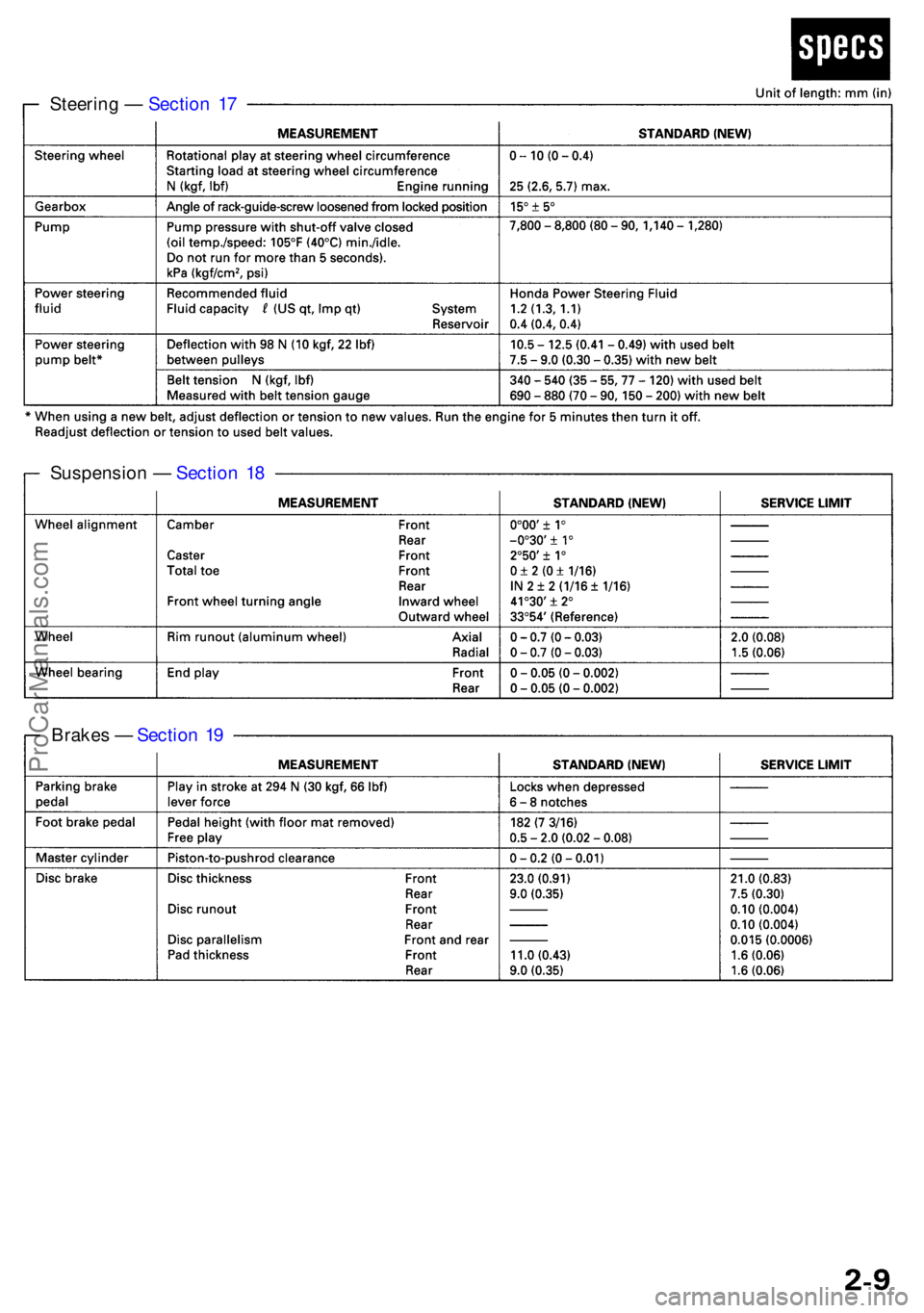
Steering — Sectio n 1 7
Suspensio n — Sectio n 1 8
Brake s — Sectio n 1 9
ProCarManuals.com
Page 309 of 1954
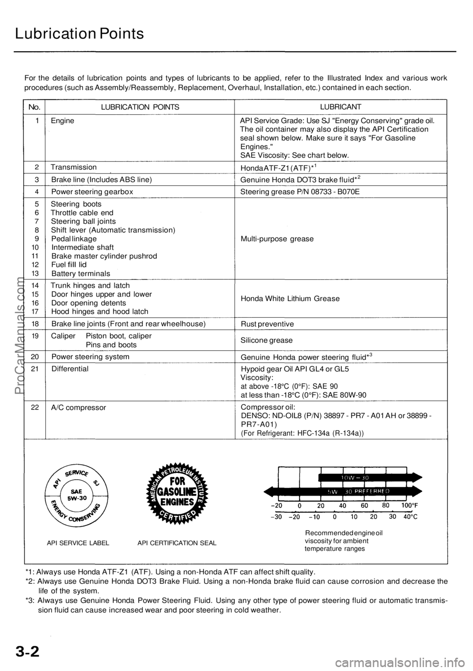
Lubrication Points
For the details of lubrication points and types of lubricants to be applied, refer to the Illustrated Index and various work
procedures (such as Assembly/Reassembly, Replacement, Overhaul, Installation, etc.) contained in each section.
No.
1
2
3
4
5
6
7
8
9
10
11
12
13
14
15
16
17
18
19
20
21
22
LUBRICATION POINTS
Engine
Transmission
Brake line (Includes ABS line)
Power steering gearbox
Steering boots
Throttle cable end
Steering ball joints
Shift lever (Automatic transmission)
Pedal linkage
Intermediate shaft
Brake master cylinder pushrod
Fuel
fill
lid
Battery terminals
Trunk hinges and latch
Door hinges upper and lower
Door opening detents
Hood hinges and hood latch
Brake line joints (Front and rear wheelhouse)
Caliper Piston boot, caliper
Pins and boots
Power steering system
Differential
A/C compressor
API SERVICE LABEL API CERTIFICATION SEAL
LUBRICANT
API Service Grade: Use SJ "Energy Conserving" grade oil.
The oil container may also display the API Certification
seal shown below. Make sure it says "For Gasoline
Engines."
SAE Viscosity: See chart below.
Honda ATF-Z1 (ATF)*1
Genuine Honda DOT3 brake fluid*2
Steering grease P/N 08733 - B070E
Multi-purpose grease
Honda White Lithium Grease
Rust preventive
Silicone grease
Genuine Honda power steering fluid*3
Hypoid gear Oil API GL4 or GL5
Viscosity:
at above -18°C (0°F): SAE 90
at less than -18°C (0°F): SAE 80W-90
Compressor oil:
DENSO: ND-OIL8 (P/N) 38897 - PR7 - A01 AH or 38899 -
PR7-A01)
(For Refrigerant: HFC-134a (R-134a))
Recommended engine oil
viscosity for ambient
temperature ranges
*1: Always use Honda ATF-Z1 (ATF). Using a non-Honda ATF can affect shift quality.
*2: Always use Genuine Honda DOT3 Brake Fluid. Using a non-Honda brake fluid can cause corrosion and decrease the
life of the system.
*3: Always use Genuine Honda Power Steering Fluid. Using any other type of power steering fluid or automatic transmis-
sion fluid can cause increased wear and poor steering in cold weather.ProCarManuals.com
Page 356 of 1954

Cruise Control
Control Unit Input Test (cont'd)
Cavity Wire
Test condition
Test: Desired result
Possible cause if result is not obtained
3
13
7
6
14
12
2
5
10
9
11
1
BLK
LT GRN
LT GRN/BLK
LT GRN/RED
PNK
BLU/WHT
GRY
GRN/WHT
BLU/YEL
BRN
BRN/BLK
BRN/WHT
Under all conditions
Ignition switch ON (II) and
main switch ON
Resume button pushed
Cancel button pushed
Set button pushed
Cancel button pushed
Shift lever in , or
Ignition switch ON (II), and
main switch ON; raise the
front of the vehicle, and rotate
one wheel slowly while
holding the other wheel.
Ignition switch ON (II), main
switch ON; brake pedal
pressed, then released
Brake pedal pressed then
released
Ignition switch ON (II)
Under all conditions
Under all conditions
Under all conditions
Check for continuity to ground:
There should be continuity.
Check for voltage to ground:
There should be battery voltage.
Check for voltage to ground:
There should be battery voltage.
When testing terminal No. 7, there
should be no voltage on terminal No. 6.
Check for voltage to ground:
There should be battery voltage.
When testing terminal No. 7, there
should be voltage on terminal No. 6.
Check for voltage to ground:
There should be battery voltage.
When testing terminal No. 6, there
should be no voltage on terminal No. 7.
Check for voltage to ground:
There should be battery voltage.
When testing terminal No. 6, there
should be voltage on terminal No. 7.
Check for continuity to ground:
There should be continuity.
NOTE: There should be no continuity
when the shift lever is in other positions.
Check for voltage between the
BLU/ WHT and BLK terminals:
There should be cycle 0 - 5 V or
battery voltage.
Check for voltage to ground:
There should be 0 V with the pedal
pressed, and battery voltage with
the pedal released.
Check for voltage to ground:
There should be battery voltage with
the pedal pressed, and 0 V with the
pedal released.
Attach to ground:
The cruise light in the gauge assembly
should come on.
Check for resistance to ground:
There should be 80 -120
Check for resistance to ground:
There should be 70 -110
Check for resistance to ground:
There should be 40 - 60
• Poor ground (G401, G402)
• An open in the wire
• Blown No. 20 (20 A) fuse in the
under-dash fuse/relay box
• Faulty main switch
• An open in the wire
• Blown No. 39 (15 A) fuse in the
under-hood fuse/relay box
• Faulty horn relay
• Faulty set/resume/cancel switch
• Faulty cable reel
• An open in the wire
• Short between LT GRN/BLK and
LT GRN/RED wires
• Blown No. 39 (15 A) fuse in the
under-hood fuse/relay box
• Faulty horn relay
• Faulty set/resume/cancel switch
• Faulty cable reel
• An open in the wire
• Blown No. 39 (15 A) fuse in the
under-hood fuse/relay box
• Faulty horn relay
• Faulty set/resume/cancel switch
• Faulty cable reel
• An open in the wire
• Short between LT GRN/BLK and
LT GRN/RED wires
• Blown No. 39 (15 A) fuse in the
under-hood fuse/relay box
• Faulty horn relay
• Faulty set/resume/cancel switch
• Faulty cable reel
• An open in the wire
• Faulty A/T gear position switch
• Poor ground (G401, G402)
• An open in the wire
• Faulty vehicle speed sensor (VSS)
• An open in the wire
• Short to ground
• Blown No. 39 (15 A) fuse in the
under-hood fuse/relay box
• Faulty brake switch
• An open in the wire
• Blown No. 39 (15 A) fuse in the
under-hood fuse/relay box
• Faulty brake switch
• An open in the wire
• Blown bulb
• Faulty gauge circuit
• An open in the wire
• Faulty actuator solenoid
• An open in the wireProCarManuals.com