Crankshaft pulley ACURA RL KA9 1996 Service Repair Manual
[x] Cancel search | Manufacturer: ACURA, Model Year: 1996, Model line: RL KA9, Model: ACURA RL KA9 1996Pages: 1954, PDF Size: 61.44 MB
Page 385 of 1954
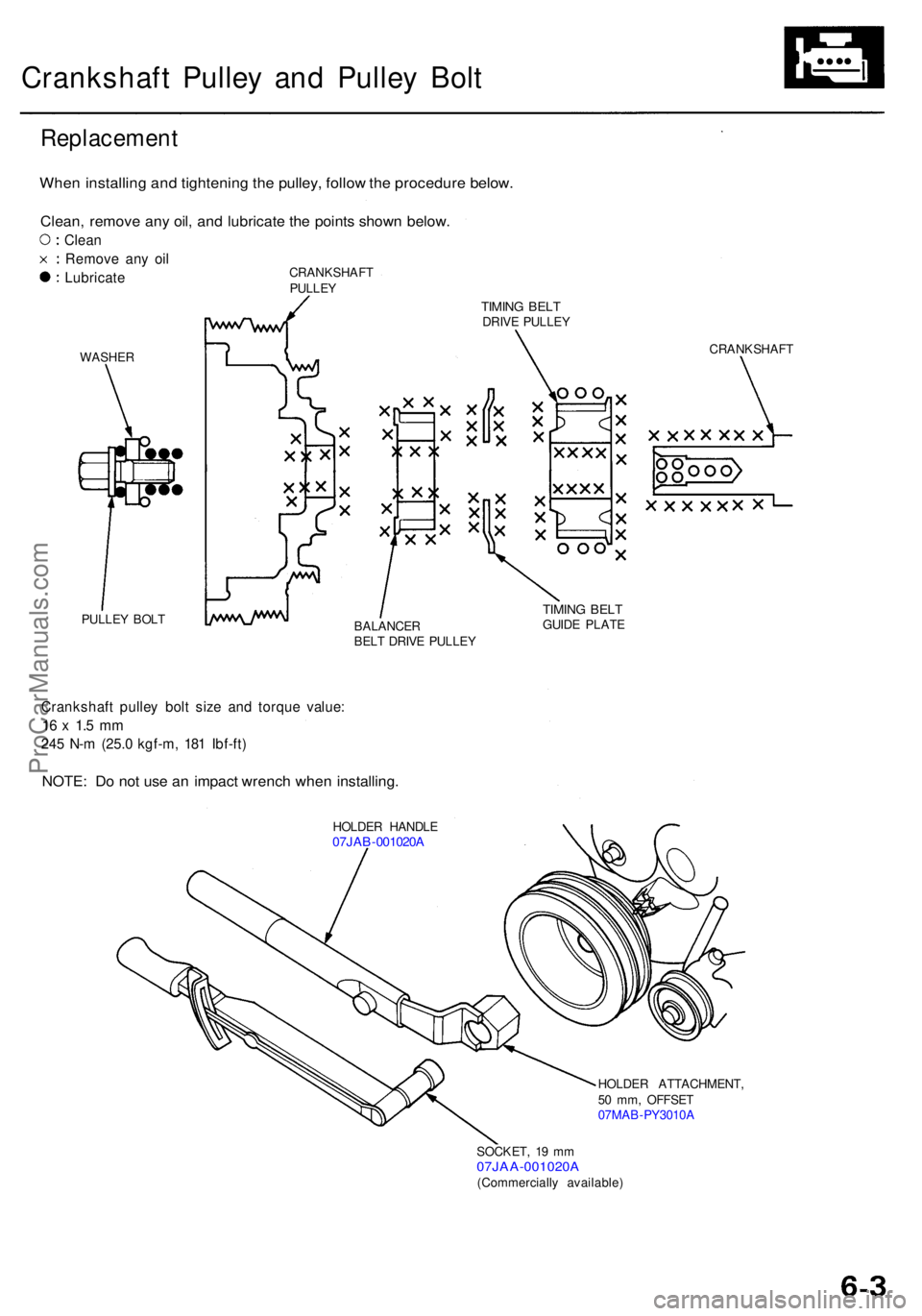
Crankshaft Pulle y an d Pulle y Bol t
Replacemen t
When installin g an d tightenin g th e pulley , follo w th e procedur e below .
Clean, remov e an y oil , an d lubricat e th e point s show n below .
Clean
Remov e an y oi l
Lubricat e
WASHER
PULLE Y BOL T CRANKSHAF
T
PULLE Y
TIMING BEL TDRIV E PULLE Y
CRANKSHAFT
BALANCE R
BEL T DRIV E PULLE Y
TIMING BEL TGUID E PLAT E
Crankshaf t pulle y bol t siz e an d torqu e value :
16 x 1. 5 m m
245 N- m (25. 0 kgf-m , 18 1 Ibf-ft )
HOLDE R HANDL E07JAB-001020 A
HOLDE R ATTACHMENT ,
5 0 mm , OFFSE T
07MA B-PY3010 A
SOCKET , 1 9 m m
07JAA-001020 A(Commercially available )
NOTE: D o no t us e a n impac t wrenc h whe n installing .
ProCarManuals.com
Page 394 of 1954
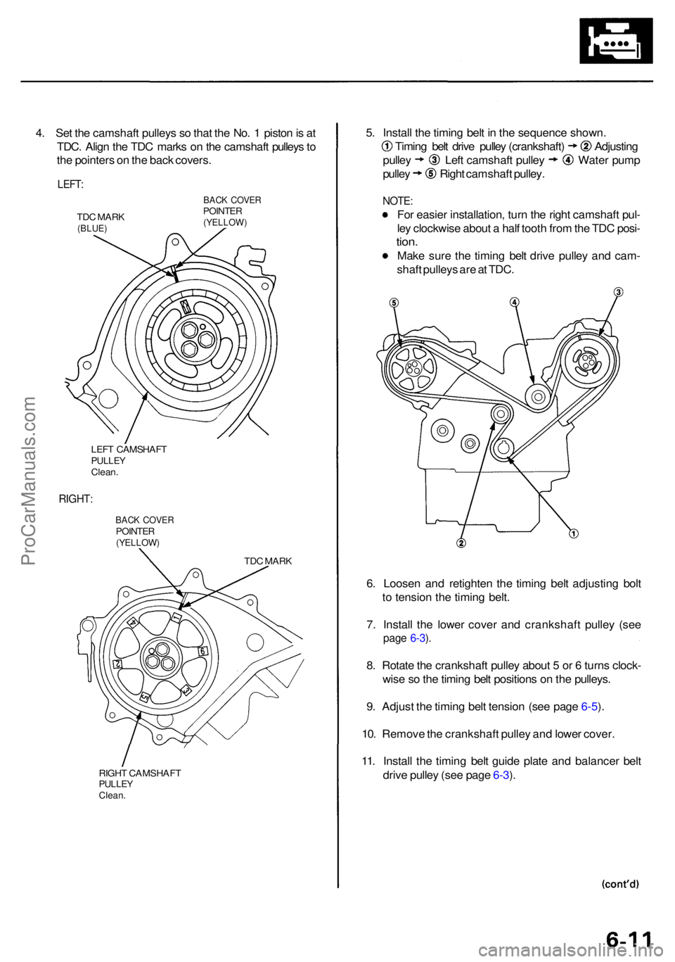
4. Se t th e camshaf t pulley s s o tha t th e No . 1 pisto n is a t
TDC . Alig n th e TD C mark s o n th e camshaf t pulley s to
th e pointer s o n th e bac k covers .
LEFT:
TDC MAR K(BLUE )
BACK COVE RPOINTE R(YELLOW )
LEFT CAMSHAF TPULLEYClean.
RIGHT :
BACK COVE RPOINTE R(YELLOW )
TDC MAR K
RIGH T CAMSHAF T
PULLEYClean.
5. Instal l th e timin g bel t i n th e sequenc e shown .
Timing bel t driv e pulle y (crankshaft ) Adjustin g
pulley Lef t camshaf t pulle y Wate r pum p
pulley Righ t camshaf t pulley .
NOTE :
For easie r installation , tur n th e righ t camshaf t pul -
le y clockwis e abou t a hal f toot h fro m th e TD C posi -
tion.
Mak e sur e th e timin g bel t driv e pulle y an d cam -
shaf t pulley s ar e a t TDC .
6 . Loose n an d retighte n th e timin g bel t adjustin g bol t
t o tensio n th e timin g belt .
7 . Instal l th e lowe r cove r an d crankshaf t pulle y (se e
page 6-3 ).
8 . Rotat e th e crankshaf t pulle y abou t 5 or 6 turn s clock -
wis e s o th e timin g bel t position s o n th e pulleys .
9 . Adjus t th e timin g bel t tensio n (se e pag e 6-5 ).
10 . Remov e th e crankshaf t pulle y an d lowe r cover .
11 . Instal l th e timin g bel t guid e plat e an d balance r bel t
driv e pulle y (se e pag e 6-3 ).
ProCarManuals.com
Page 435 of 1954
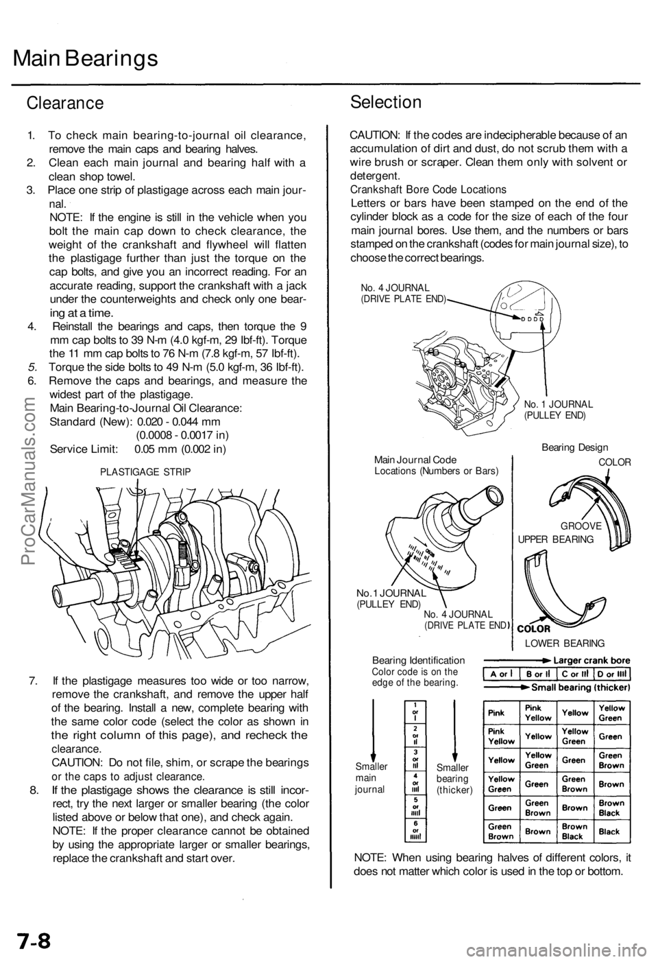
Main Bearing s
Clearanc e
1. T o chec k mai n bearing-to-journa l oi l clearance ,
remov e th e mai n cap s an d bearin g halves .
2 . Clea n eac h mai n journa l an d bearin g hal f wit h a
clea n sho p towel .
3 . Plac e on e stri p o f plastigag e acros s eac h mai n jour -
nal.
NOTE : I f th e engin e is stil l i n th e vehicl e whe n yo u
bol t th e mai n ca p dow n t o chec k clearance , th e
weigh t o f th e crankshaf t an d flywhee l will flatte n
th e plastigag e furthe r tha n jus t th e torqu e o n th e
ca p bolts , an d giv e yo u a n incorrec t reading . Fo r a n
accurat e reading , suppor t th e crankshaf t wit h a jac k
unde r th e counterweight s an d chec k onl y on e bear -
ing a t a time .
4. Reinstal l th e bearing s an d caps , the n torqu e th e 9
m m cap bolts to 3 9 N- m (4. 0 kgf-m , 2 9 Ibf-ft) . Torqu e
th e 1 1 m m ca p bolt s to 7 6 N- m (7. 8 kgf-m , 5 7 Ibf-ft) .
5. Torqu e th e sid e bolt s to 4 9 N- m (5. 0 kgf-m , 3 6 Ibf-ft) .
6 . Remov e th e cap s an d bearings , an d measur e th e
wides t par t o f th e plastigage .
Mai n Bearing-to-Journa l Oi l Clearance :
Standar d (New) : 0.02 0 - 0.04 4 m m
(0.000 8 - 0.001 7 in )
Servic e Limit : 0.0 5 m m (0.00 2 in )
PLASTIGAG E STRI P
Selectio n
CAUTION : I f th e code s ar e indecipherabl e becaus e o f a n
accumulatio n o f dir t an d dust , d o no t scru b the m wit h a
wir e brus h o r scraper . Clea n the m onl y wit h solven t o r
detergent .
Crankshaf t Bor e Cod e Location s
Letters o r bar s hav e bee n stampe d o n th e en d of the
cylinde r bloc k a s a cod e fo r th e siz e o f eac h o f th e fou r
mai n journa l bores . Us e them , an d th e number s o r bar s
stampe d o n th e crankshaf t (code s fo r mai n journa l size) , t o
choos e th e correc t bearings .
No. 4 JOURNA L(DRIVE PLAT E END )
No. 1 JOURNA L(PULLEY END )
Main Journa l Cod eLocation s (Number s o r Bars )
Bearin g Desig n
COLO R
No. 1 JOURNA L(PULLEY END )No. 4 JOURNA L(DRIVE PLAT E EN D
Bearin g Identificatio nColor cod e i s o n th eedg e o f th e bearing .
LOWER BEARIN G
GROOVE
UPPER BEARIN G
NOTE: Whe n usin g bearin g halve s o f differen t colors , i t
doe s no t matte r whic h colo r i s use d in th e to p o r bottom .
Smallermainjourna l
Smalle rbearing(thicker )
7. I f th e plastigag e measure s to o wid e o r to o narrow ,
remov e th e crankshaft , an d remov e th e uppe r hal f
o f th e bearing . Instal l a new , complet e bearin g wit h
th e sam e colo r cod e (selec t th e colo r a s show n i n
th e righ t colum n o f thi s page) , an d rechec k th e
clearance .
CAUTION: D o no t file , shim , o r scrap e th e bearing s
or th e cap s t o adjus t clearance .
8. I f th e plastigag e show s th e clearanc e is stil l incor -
rect, tr y th e nex t large r o r smalle r bearin g (th e colo r
liste d abov e o r belo w tha t one) , an d chec k again .
NOTE : I f th e prope r clearanc e canno t b e obtaine d
b y usin g th e appropriat e large r o r smalle r bearings ,
replac e th e crankshaf t an d star t over .
ProCarManuals.com
Page 826 of 1954
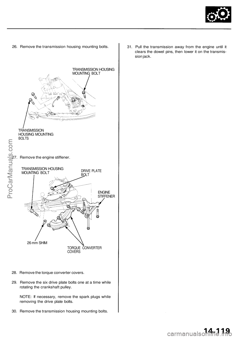
26. Remove the transmission housing mounting bolts.
TRANSMISSION HOUSING
MOUNTING BOLT
TRANSMISSION
HOUSING MOUNTING
BOLTS
27. Remove the engine stiffener.
TRANSMISSION HOUSING
MOUNTING BOLT
DRIVE PLATE
BOLT
ENGINE
STIFFENER
26 mm SHIM
TORQUE CONVERTER
COVERS
28. Remove the torque converter covers.
29. Remove the six drive plate bolts one at a time while
rotating the crankshaft pulley.
NOTE: If necessary, remove the spark plugs while
removing the drive plate bolts.
30. Remove the transmission housing mounting bolts.
31. Pull the transmission away from the engine until it
clears the dowel pins, then lower it on the transmis-
sion jack.ProCarManuals.com