boot ACURA RL KA9 1996 Service Repair Manual
[x] Cancel search | Manufacturer: ACURA, Model Year: 1996, Model line: RL KA9, Model: ACURA RL KA9 1996Pages: 1954, PDF Size: 61.44 MB
Page 262 of 1954
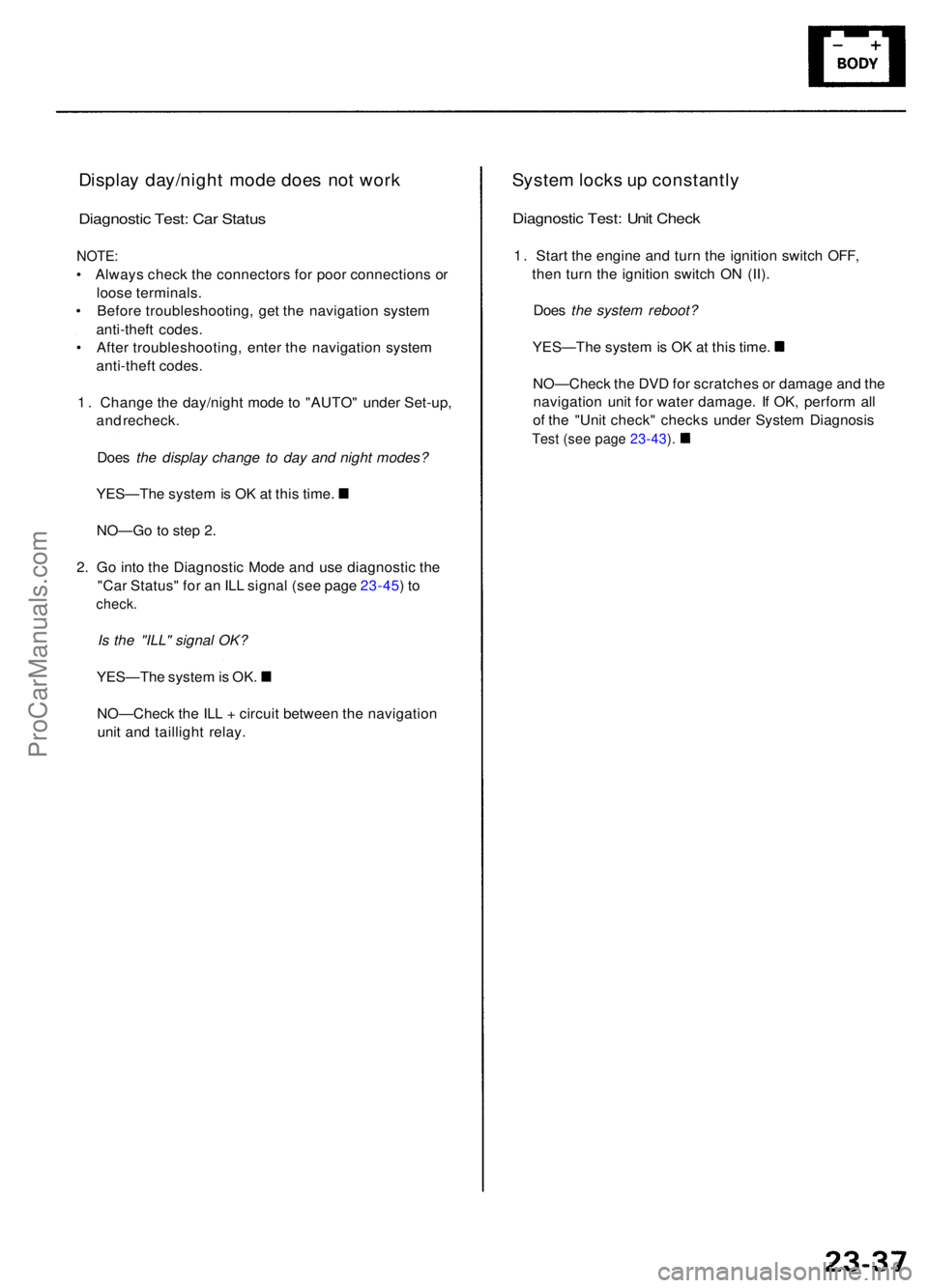
Display day/nigh t mod e doe s no t wor k
Diagnosti c Test : Ca r Statu s
NOTE :
• Alway s chec k th e connector s fo r poo r connection s o r
loos e terminals .
• Befor e troubleshooting , ge t th e navigatio n syste m
anti-thef t codes .
• Afte r troubleshooting , ente r th e navigatio n syste m
anti-thef t codes .
1 . Chang e th e day/nigh t mod e t o "AUTO " unde r Set-up ,
an d recheck .
Doe s the display change to day and night modes?
YES—Th e syste m is O K a t thi s time .
NO—G o to ste p 2 .
2 . G o int o th e Diagnosti c Mod e an d us e diagnosti c th e
"Ca r Status " fo r a n IL L signa l (se e pag e 23-45 ) t o
check .
Is the "ILL" signal OK?
YES—Th e syste m is OK .
NO—Chec k th e IL L + circui t betwee n th e navigatio n
uni t an d tailligh t relay .
System lock s u p constantl y
Diagnostic Test : Uni t Chec k
1. Star t th e engin e an d tur n th e ignitio n switc h OFF ,
the n tur n th e ignitio n switc h O N (II) .
Doe s the system reboot?
YES—Th e syste m is O K a t thi s time .
NO—Chec k th e DV D fo r scratche s o r damag e an d th e
navigatio n uni t fo r wate r damage . I f OK , perfor m al l
o f th e "Uni t check " check s unde r Syste m Diagnosi s
Test (se e pag e 23-43 ).
ProCarManuals.com
Page 269 of 1954
Navigation Syste m
System Diagnosi s Mod e (cont'd )
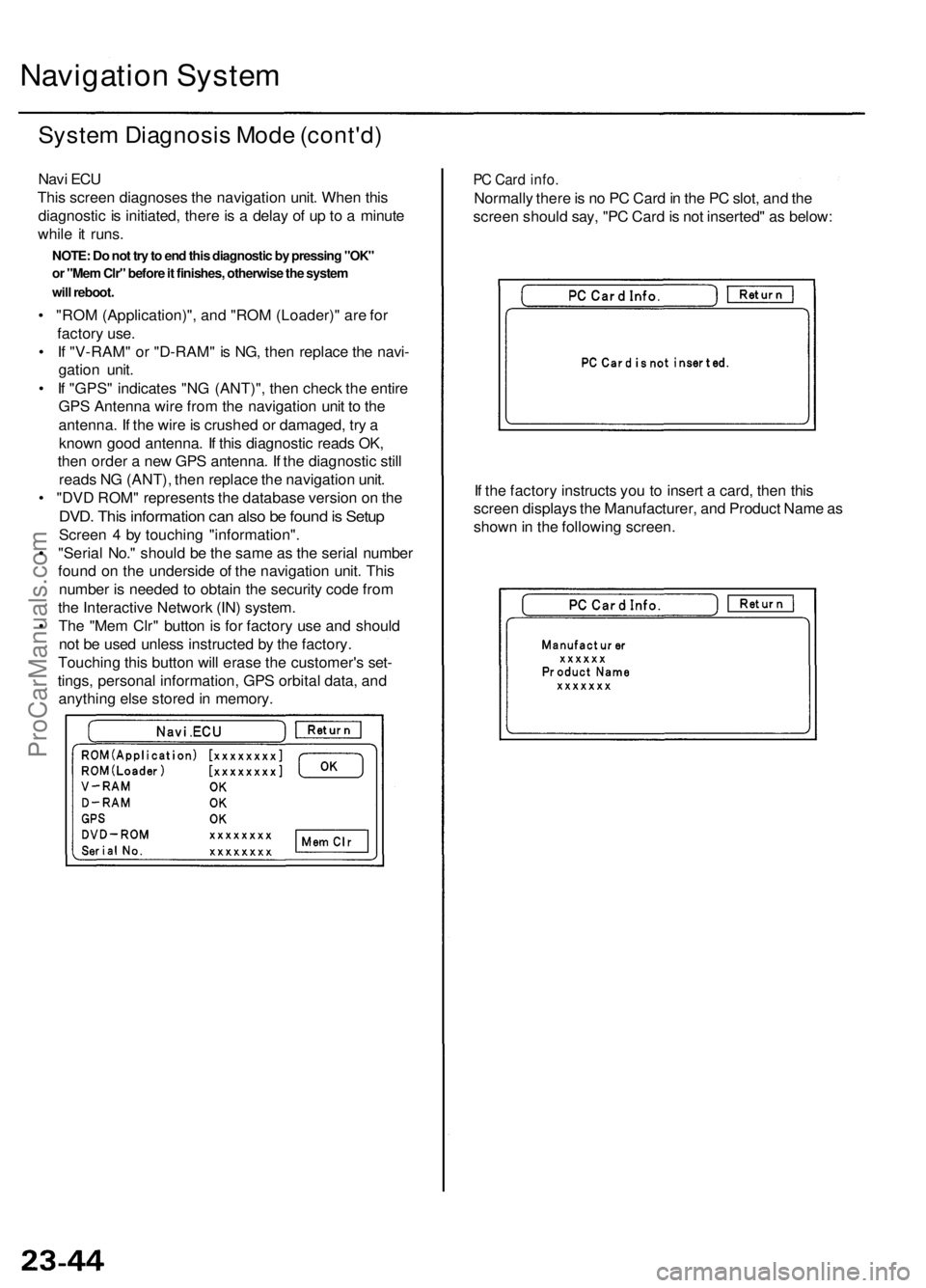
Navi EC U
Thi s scree n diagnose s th e navigatio n unit . Whe n thi s
diagnosti c i s initiated , ther e is a dela y o f u p to a minut e
whil e it runs .
• "RO M (Application)" , an d "RO M (Loader) " ar e fo r
factor y use .
• I f "V-RAM " o r "D-RAM " i s NG , the n replac e th e navi -
gatio n unit .
• I f "GPS " indicate s "N G (ANT)" , the n chec k th e entir e
GP S Antenn a wir e fro m th e navigatio n uni t t o th e
antenna . I f th e wir e is crushe d o r damaged , tr y a
know n goo d antenna . I f thi s diagnosti c read s OK ,
the n orde r a ne w GP S antenna . I f th e diagnosti c stil l
read s N G (ANT) , the n replac e th e navigatio n unit .
• "DV D ROM " represent s th e databas e versio n o n th e
DVD . Thi s informatio n ca n als o b e foun d is Setu p
Scree n 4 by touchin g "information" .
• "Seria l No. " shoul d b e th e sam e a s th e seria l numbe r
foun d o n th e undersid e o f th e navigatio n unit . Thi s
numbe r i s neede d t o obtai n th e securit y cod e fro m
th e Interactiv e Networ k (IN ) system .
• Th e "Me m Clr " butto n is fo r factor y us e an d shoul d
no t b e use d unles s instructe d b y th e factory .
Touchin g thi s butto n wil l eras e th e customer' s set -
tings , persona l information , GP S orbita l data , an d
anythin g els e store d in memory .
PC Car d info .
Normall y ther e is n o P C Car d in th e P C slot , an d th e
scree n shoul d say , "P C Car d is no t inserted " a s below :
I f th e factor y instruct s yo u t o inser t a card , the n thi s
scree n display s th e Manufacturer , an d Produc t Nam e a s
show n in th e followin g screen .
NOTE: Do not try to end this diagnostic by pressing "OK"
or "Mem Clr" before it finishes, otherwise the system
will reboot.
ProCarManuals.com
Page 309 of 1954
Lubrication Points
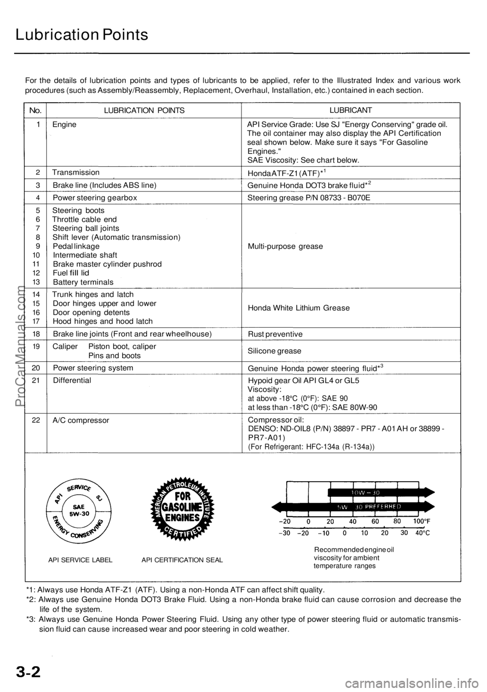
For the details of lubrication points and types of lubricants to be applied, refer to the Illustrated Index and various work
procedures (such as Assembly/Reassembly, Replacement, Overhaul, Installation, etc.) contained in each section.
No.
1
2
3
4
5
6
7
8
9
10
11
12
13
14
15
16
17
18
19
20
21
22
LUBRICATION POINTS
Engine
Transmission
Brake line (Includes ABS line)
Power steering gearbox
Steering boots
Throttle cable end
Steering ball joints
Shift lever (Automatic transmission)
Pedal linkage
Intermediate shaft
Brake master cylinder pushrod
Fuel
fill
lid
Battery terminals
Trunk hinges and latch
Door hinges upper and lower
Door opening detents
Hood hinges and hood latch
Brake line joints (Front and rear wheelhouse)
Caliper Piston boot, caliper
Pins and boots
Power steering system
Differential
A/C compressor
API SERVICE LABEL API CERTIFICATION SEAL
LUBRICANT
API Service Grade: Use SJ "Energy Conserving" grade oil.
The oil container may also display the API Certification
seal shown below. Make sure it says "For Gasoline
Engines."
SAE Viscosity: See chart below.
Honda ATF-Z1 (ATF)*1
Genuine Honda DOT3 brake fluid*2
Steering grease P/N 08733 - B070E
Multi-purpose grease
Honda White Lithium Grease
Rust preventive
Silicone grease
Genuine Honda power steering fluid*3
Hypoid gear Oil API GL4 or GL5
Viscosity:
at above -18°C (0°F): SAE 90
at less than -18°C (0°F): SAE 80W-90
Compressor oil:
DENSO: ND-OIL8 (P/N) 38897 - PR7 - A01 AH or 38899 -
PR7-A01)
(For Refrigerant: HFC-134a (R-134a))
Recommended engine oil
viscosity for ambient
temperature ranges
*1: Always use Honda ATF-Z1 (ATF). Using a non-Honda ATF can affect shift quality.
*2: Always use Genuine Honda DOT3 Brake Fluid. Using a non-Honda brake fluid can cause corrosion and decrease the
life of the system.
*3: Always use Genuine Honda Power Steering Fluid. Using any other type of power steering fluid or automatic transmis-
sion fluid can cause increased wear and poor steering in cold weather.ProCarManuals.com
Page 944 of 1954
Driveshafts
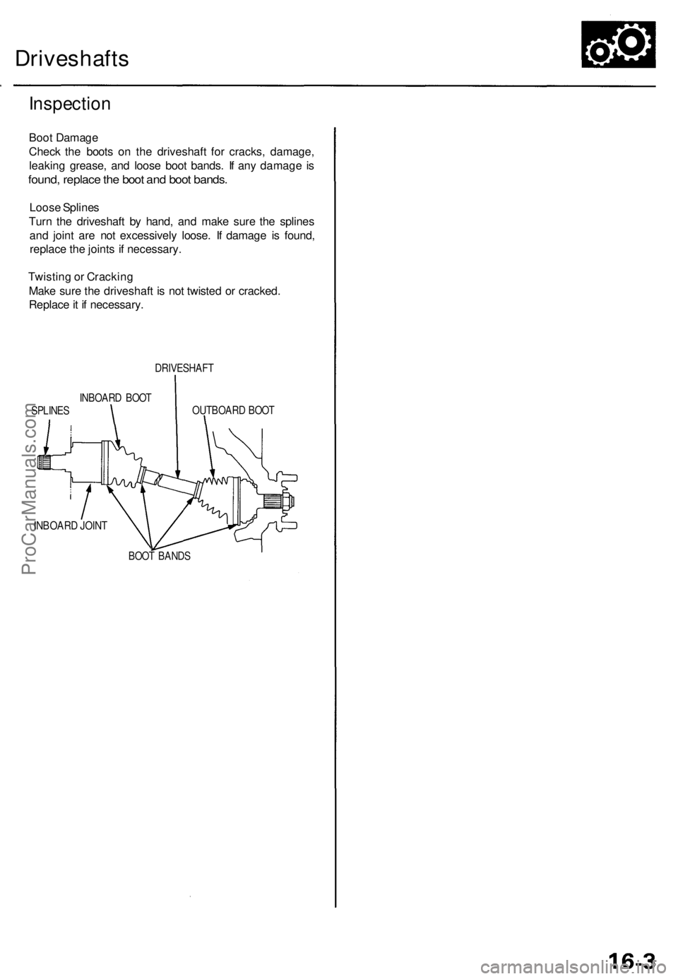
Inspection
Boot Damage
Check the boots on the driveshaft for cracks, damage,
leaking grease, and loose boot bands. If any damage is
found, replace the boot and boot bands.
Loose Splines
Turn the driveshaft by hand, and make sure the splines
and joint are not excessively loose. If damage is found,
replace the joints if necessary.
Twisting or Cracking
Make sure the driveshaft is not twisted or cracked.
Replace it if necessary.
DRIVESHAFT
INBOARD BOOT
SPLINES
OUTBOARD BOOT
INBOARD JOINT
BOOT BANDSProCarManuals.com
Page 946 of 1954
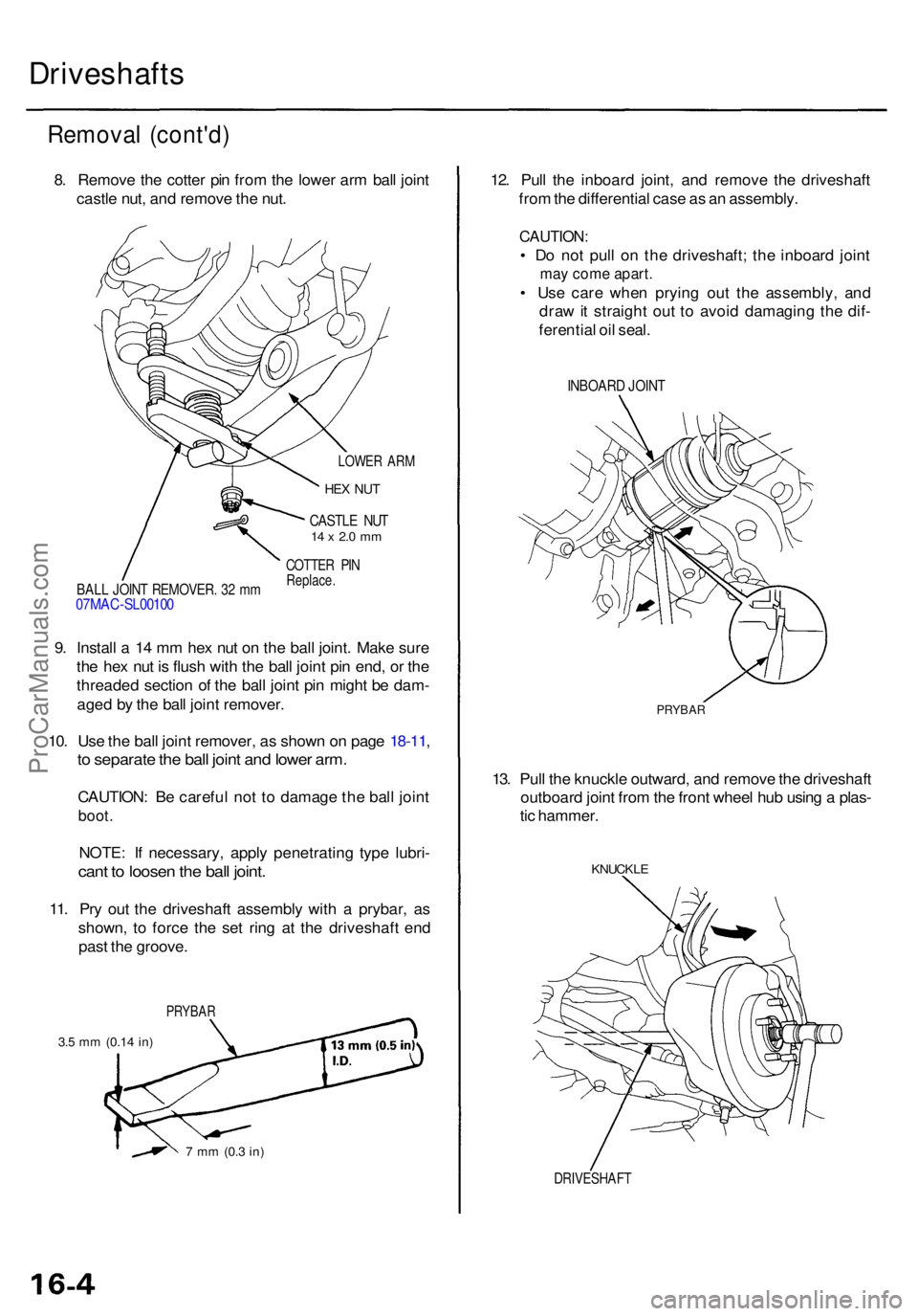
DRIVESHAFT
KNUCKLE
13. Pul l th e knuckl e outward , an d remov e th e driveshaf t
outboar d join t fro m th e fron t whee l hu b usin g a plas -
ti c hammer .
12
. Pul l th e inboar d joint , an d remov e th e driveshaf t
fro m th e differentia l cas e a s a n assembly .
CAUTION:
• D o no t pul l o n th e driveshaft ; th e inboar d join t
may com e apart .
• Us e car e whe n pryin g ou t th e assembly , an d
dra w it straigh t ou t t o avoi d damagin g th e dif -
ferentia l oi l seal .
INBOAR D JOIN T
Remova l (cont'd )
8. Remov e th e cotte r pi n fro m th e lowe r ar m bal l join t
castl e nut , an d remov e th e nut .
Driveshaft s
LOWER AR M
HEX NU T
CASTL E NU T14 x 2. 0 m m
COTTE R PI NReplace .BALL JOIN T REMOVER . 3 2 m m07MA C-SL0010 0
9. Instal l a 14 m m he x nu t o n th e bal l joint . Mak e sur e
th e he x nu t i s flus h wit h th e bal l join t pi n end , o r th e
threade d sectio n o f th e bal l join t pi n migh t b e dam -
age d b y th e bal l join t remover .
10 . Us e th e bal l join t remover , a s show n o n pag e 18-11 ,
to separat e th e bal l join t an d lowe r arm .
CAUTION : B e carefu l no t t o damag e th e bal l join t
boot .
NOTE : I f necessary , appl y penetratin g typ e lubri -
cant t o loose n th e bal l joint .
11. Pr y ou t th e driveshaf t assembl y wit h a prybar , a s
shown , t o forc e th e se t rin g a t th e driveshaf t en d
pas t th e groove .
PRYBA R
3.5 m m (0.1 4 in)
7 m m (0. 3 in)
PRYBA R
ProCarManuals.com
Page 947 of 1954
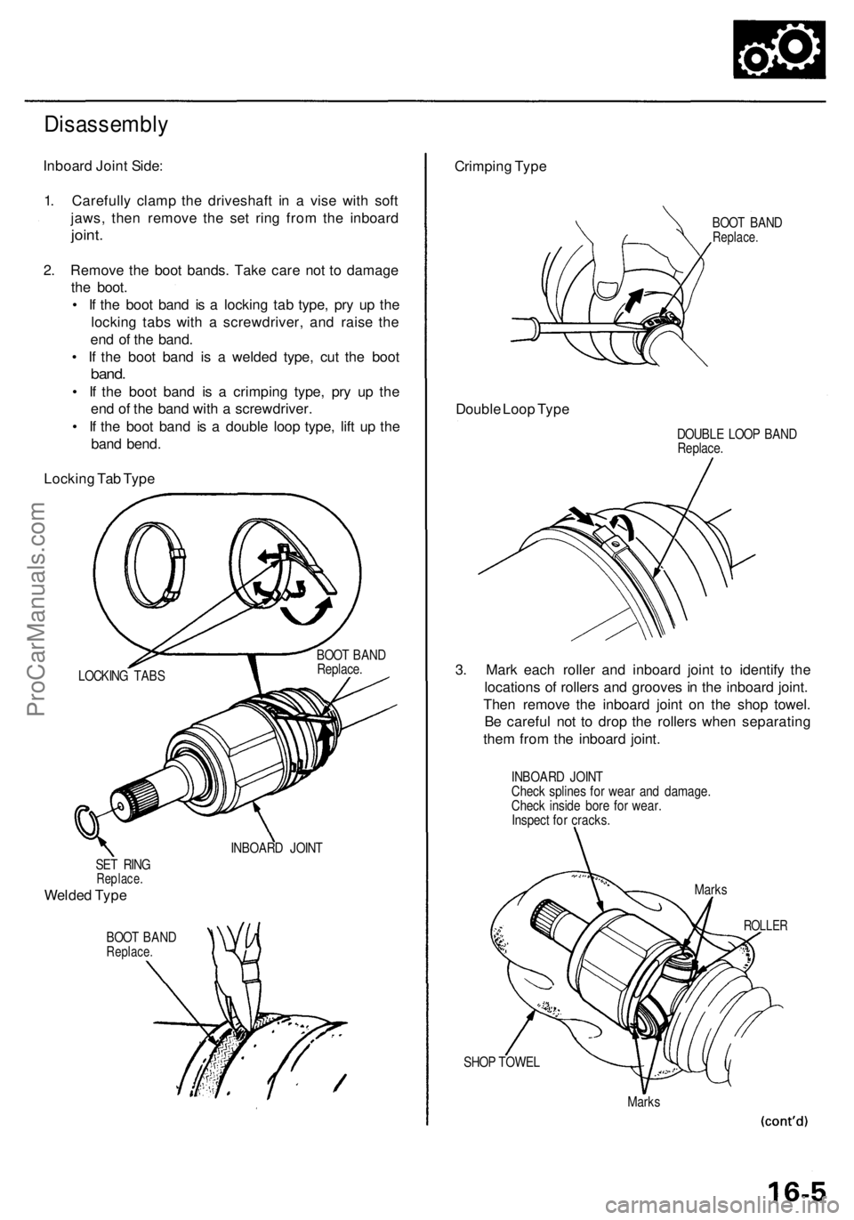
SET RIN GReplace .
Welded Typ e
BOO T BAN DReplace .
INBOARD JOIN T
SHOP TOWE L
Marks
Crimpin g Typ e
BOO T BAN DReplace .
Double Loo p Typ e
DOUBL E LOO P BAN DReplace .
3. Mar k eac h rolle r an d inboar d join t t o identif y th e
location s o f roller s an d groove s in th e inboar d joint .
The n remov e th e inboar d join t o n th e sho p towel .
B e carefu l no t t o dro p th e roller s whe n separatin g
the m fro m th e inboar d joint .
INBOAR D JOIN T
Chec k spline s fo r wea r an d damage .
Chec k insid e bor e fo r wear .
Inspec t fo r cracks .
ROLLER
Marks
Disassembl y
Inboard Join t Side :
1 . Carefull y clam p th e driveshaf t i n a vis e wit h sof t
jaws , the n remov e th e se t rin g fro m th e inboar d
joint.
2. Remov e th e boo t bands . Tak e car e no t t o damag e
th e boot .
• I f th e boo t ban d i s a lockin g ta b type , pr y u p th e
lockin g tab s wit h a screwdriver , an d rais e th e
en d o f th e band .
• I f th e boo t ban d i s a welde d type , cu t th e boo t
band.
• I f th e boo t ban d i s a crimpin g type , pr y u p th e
en d o f th e ban d wit h a screwdriver .
• I f th e boo t ban d i s a doubl e loo p type , lif t u p th e
ban d bend .
Lockin g Ta b Typ e
LOCKIN G TAB S BOO
T BAN D
Replace .
ProCarManuals.com
Page 948 of 1954
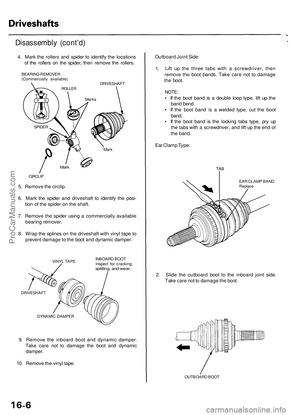
9. Remov e th e inboar d boo t an d dynami c damper .
Tak e car e no t t o damag e th e boo t an d dynami c
damper .
10 . Remov e th e viny l tape .
DYNAMI C DAMPE R INBOAR
D BOO T
Inspec t fo r cracking ,
splitting, an d wear .
VINY L TAP E
DRIVESHAF T
5. Remov e th e circlip .
6 . Mar k th e spide r an d driveshaf t t o identif y th e posi -
tio n o f th e spide r o n th e shaft .
7 . Remov e th e spide r usin g a commerciall y availabl e
bearin g remover .
8 . Wra p th e spline s o n th e driveshaf t wit h viny l tap e t o
preven t damag e to th e boo t an d dynami c damper .
CIRCLIP
Mark
Mar k
SPIDE R
Disassembl y (cont'd )
4. Mar k th e roller s an d spide r t o identif y th e location s
o f th e roller s o n th e spider , the n remov e th e rollers .
BEARIN G REMOVE R
(Commerciall y available )
ROLLER
Marks
DRIVESHAF T
Outboard Join t Side :
1 . Lif t u p th e thre e tab s wit h a screwdriver , the n
remov e th e boo t bands . Tak e car e no t t o damag e
th e boot .
NOTE :
• I f th e boo t ban d i s a doubl e loo p type , lif t u p th e
ban d bend .
• I f th e boo t ban d i s a welde d type , cu t th e boo t
band .
• I f th e boo t ban d i s th e lockin g tab s type , pr y u p
th e tab s wit h a screwdriver , an d lif t u p th e en d o f
th e band .
Ea r Clam p Type :
EAR CLAM P BAN DReplace .
TAB
2. Slid e th e outboar d boo t t o th e inboar d join t side .
Tak e car e no t t o damag e th e boot .
OUTBOAR D BOO T
ProCarManuals.com
Page 949 of 1954
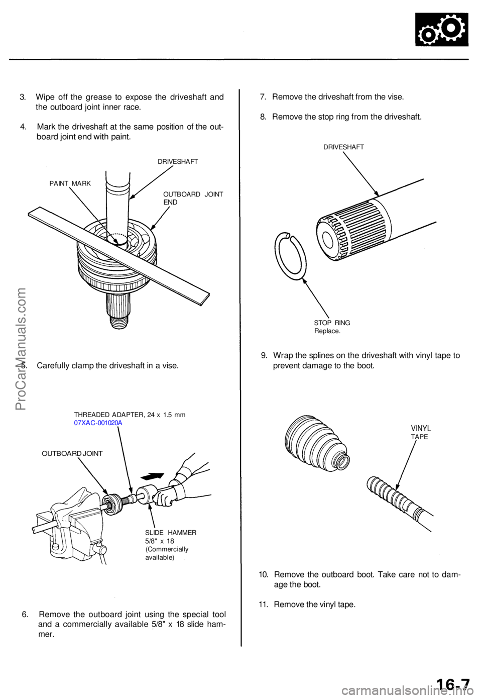
6. Remov e th e outboar d join t usin g th e specia l too l
an d a commerciall y availabl e 5/8 " x 1 8 slid e ham -
mer.
SLID E HAMME R5/8" x 1 8(Commerciall y
available )
OUTBOAR D JOIN T
THREADE D ADAPTER , 2 4 x 1. 5 m m
07XA C-001020 A
10. Remov e th e outboar d boot . Tak e car e no t t o dam -
ag e th e boot .
11 . Remov e th e viny l tape .
7
. Remov e th e driveshaf t fro m th e vise .
8 . Remov e th e sto p rin g fro m th e driveshaft .
DRIVESHAF T
STO P RIN G
Replace .
9. Wra p th e spline s o n th e driveshaf t wit h viny l tap e t o
preven t damag e to th e boot .
VINY LTAPE
5. Carefull y clam p th e driveshaf t i n a vise .
OUTBOAR D JOIN TEND
PAIN T MAR K DRIVESHAF
T
3. Wip e of f th e greas e t o expos e th e driveshaf t an d
th e outboar d join t inne r race .
4 . Mar k th e driveshaf t a t th e sam e positio n o f th e out -
boar d join t en d wit h paint .
ProCarManuals.com
Page 950 of 1954
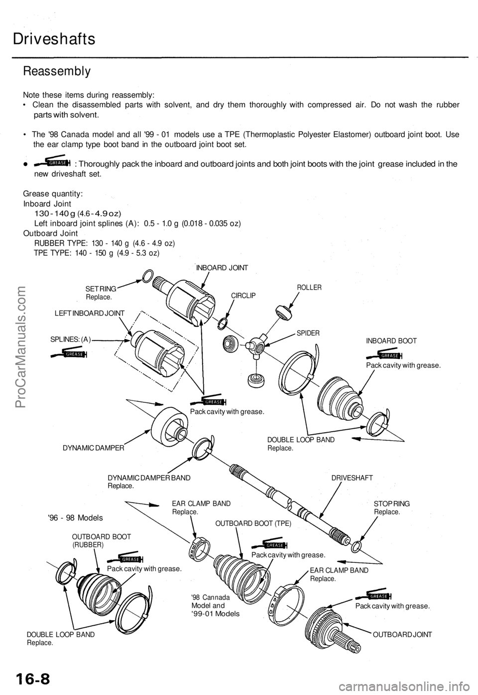
Driveshafts
Reassembl y
Note thes e item s durin g reassembly :
• Clea n th e disassemble d part s wit h solvent , an d dr y the m thoroughl y wit h compresse d air . D o no t was h th e rubbe r
parts wit h solvent .
• Th e '9 8 Canad a mode l an d al l '9 9 - 0 1 model s us e a TP E (Thermoplasti c Polyeste r Elastomer ) outboar d join t boot . Us e
th e ea r clam p typ e boo t ban d i n th e outboar d join t boo t set .
ne w driveshaf t set .
: Thoroughl y pac k th e inboar d an d outboar d joint s an d bot h join t boot s wit h th e join t greas e include d in th e
Greas e quantity :
Inboar d Join t
130 - 14 0 g (4. 6 - 4. 9 oz )
Lef t inboar d join t spline s (A) : 0. 5 - 1. 0 g (0.01 8 - 0.03 5 oz )
Outboar d Join t
RUBBE R TYPE : 13 0 - 14 0 g (4. 6 - 4. 9 oz )
TPE TYPE : 14 0 - 15 0 g (4. 9 - 5. 3 oz )
SET RIN GReplace .
LEFT INBOAR D JOIN T
SPLINES : (A )
INBOAR D JOIN T
CIRCLI PROLLE R
SPIDERINBOAR D BOO T
Pack cavit y wit h grease .
STO P RIN G
Replace .
DRIVESHAF T
DOUBLE LOO P BAN DReplace .
Pack cavit y wit h grease .
Pack cavit y wit h grease .
OUTBOAR D JOIN T
EAR CLAM P BAN DReplace .
'98 Cannad aModel an d'99-0 1 Model s
DYNAMI C DAMPE R
DYNAMI C DAMPE R BAN D
Replace .
EAR CLAM P BAN DReplace .
OUTBOAR D BOO T (TPE )
Pack cavit y wit h grease .
Pac k cavit y wit h grease .
'96 - 9 8 Model s
OUTBOAR D BOO T(RUBBER )
DOUBLE LOO P BAN DReplace .
ProCarManuals.com
Page 952 of 1954
Driveshafts
Reassembl y (cont'd )
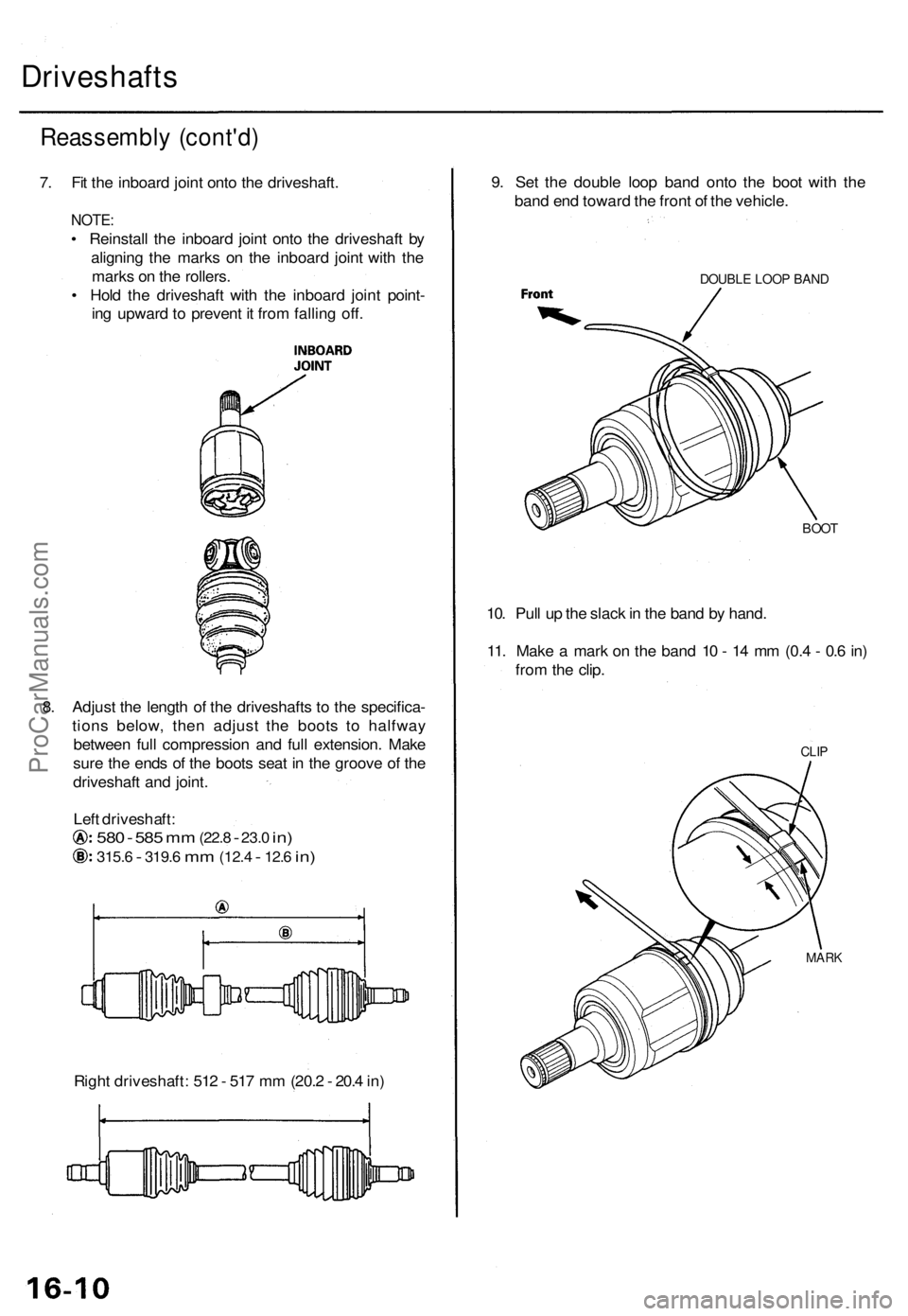
7. Fi t th e inboar d join t ont o th e driveshaft .
NOTE:
• Reinstal l th e inboar d join t ont o th e driveshaf t b y
alignin g th e mark s o n th e inboar d join t wit h th e
mark s o n th e rollers .
• Hol d th e driveshaf t wit h th e inboar d join t point -
in g upwar d to preven t i t fro m fallin g off .
8 . Adjus t th e lengt h o f th e driveshaft s t o th e specifica -
tion s below , the n adjus t th e boot s t o halfwa y
betwee n ful l compressio n an d ful l extension . Mak e
sur e th e end s o f th e boot s sea t i n th e groov e o f th e
driveshaf t an d joint .
Lef t driveshaft :
580 - 58 5 mm (22. 8 - 23.0 in)
315. 6 - 319. 6 mm (12. 4 - 12.6 in)
Righ t driveshaft : 51 2 - 51 7 m m (20. 2 - 20. 4 in ) 9
. Se t th e doubl e loo p ban d ont o th e boo t wit h th e
ban d en d towar d th e fron t o f th e vehicle .
10 . Pul l u p th e slac k in th e ban d b y hand .
11 . Mak e a mar k o n th e ban d 1 0 - 1 4 m m (0. 4 - 0. 6 in )
fro m th e clip .
DOUBL E LOO P BAN D
BOOT
MAR K
CLIP
ProCarManuals.com