check oil ACURA RL KA9 1996 Service Repair Manual
[x] Cancel search | Manufacturer: ACURA, Model Year: 1996, Model line: RL KA9, Model: ACURA RL KA9 1996Pages: 1954, PDF Size: 61.44 MB
Page 151 of 1954
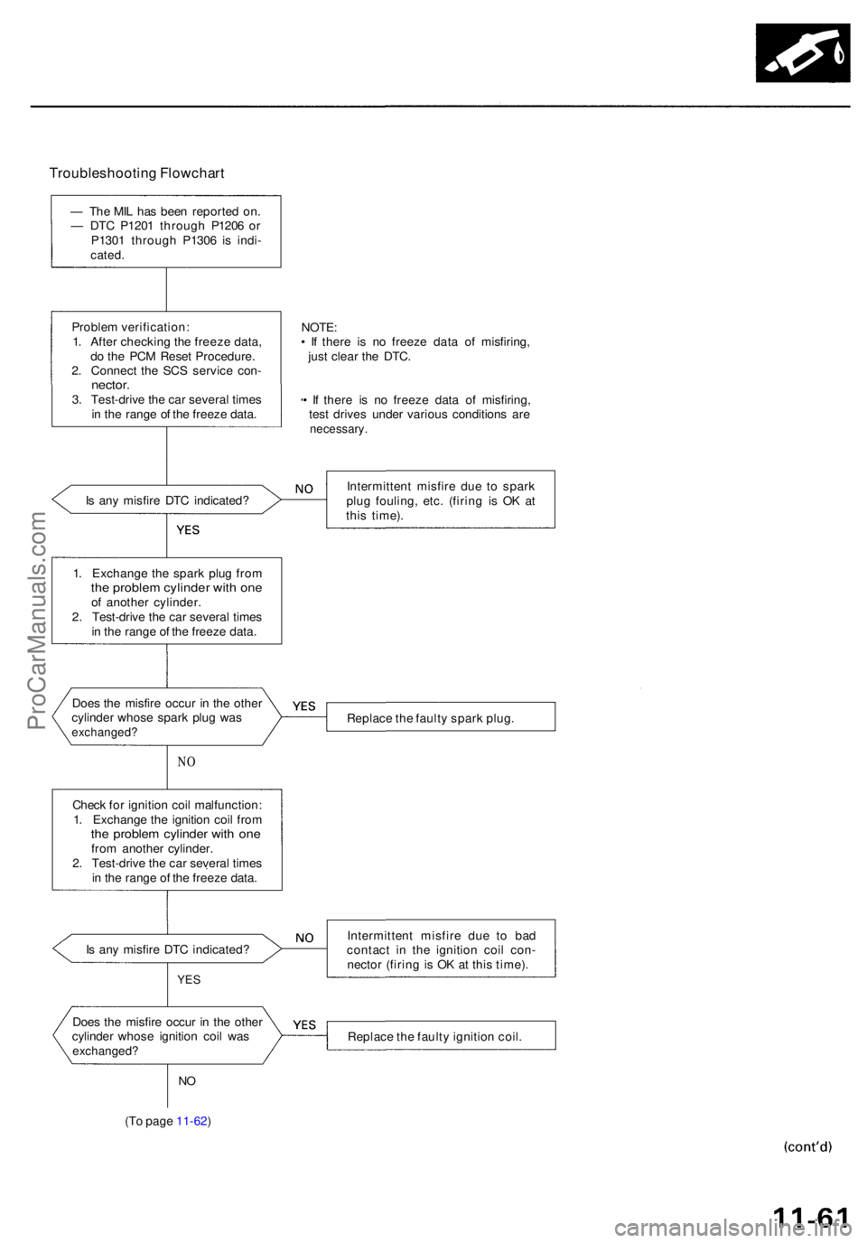
Troubleshooting Flowchar t
— Th e MI L ha s bee n reporte d on .
— DT C P120 1 throug h P120 6 o r
P130 1 throug h P130 6 i s indi -
cated .
Proble m verification :
1 . Afte r checkin g th e freez e data ,
d o th e PC M Rese t Procedure .
2 . Connec t th e SC S servic e con -
nector .3. Test-driv e th e ca r severa l time s
i n th e rang e o f th e freez e data .
I s an y misfir e DT C indicated ?
NO
Chec k fo r ignitio n coi l malfunction :
1 . Exchang e th e ignitio n coi l fro m
the proble m cylinde r wit h on efrom anothe r cylinder .
2 . Test-driv e th e ca r severa l time s
i n th e rang e o f th e freez e data .
I s an y misfir e DT C indicated ?
YES
NO
(T o pag e 11-62 )
NOTE:• I f ther e i s n o freez e dat a o f misfiring ,
jus t clea r th e DTC .
• I f ther e i s n o freez e dat a o f misfiring ,
tes t drive s unde r variou s condition s ar e
necessary .
Intermitten t misfir e du e t o spar k
plu g fouling , etc . (firin g i s O K a t
thi s time) .
Replac e th e fault y spar k plug .
Intermitten t misfir e du e t o ba d
contac t i n th e ignitio n coi l con -
necto r (firin g is O K a t thi s time) .
Replac e th e fault y ignitio n coil .
Doe
s th e misfir e occu r i n th e othe r
cylinde r whos e spar k plu g wa s
exchanged ?
Does th e misfir e occu r i n th e othe r
cylinde r whos e ignitio n coi l wa s
exchanged ?
1. Exchang e th e spar k plu g fro mthe proble m cylinde r wit h on eof anothe r cylinder .
2 . Test-driv e th e ca r severa l time s
i n th e rang e o f th e freez e data .
ProCarManuals.com
Page 154 of 1954
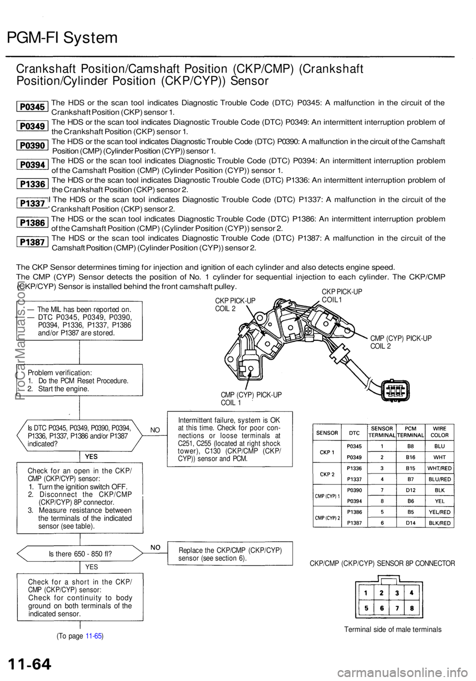
PGM-FI Syste m
Crankshaf t Position/Camshaf t Positio n (CKP/CMP ) (Crankshaf t
Position/Cylinde r Positio n (CKP/CYP) ) Senso r
The HD S o r th e sca n too l indicate s Diagnosti c Troubl e Cod e (DTC ) P0345 : A malfunctio n i n th e circui t o f th e
Crankshaf t Positio n (CKP ) senso r 1 .
Th e HD S o r th e sca n too l indicate s Diagnosti c Troubl e Cod e (DTC ) P0349 : A n intermitten t interruptio n proble m of
th e Crankshaf t Positio n (CKP ) senso r 1 .
Th e HD S o r th e sca n too l indicate s Diagnosti c Troubl e Cod e (DTC ) P0390 : A malfunctio n in th e circui t o f th e Camshaf t
Positio n (CMP ) (Cylinde r Positio n (CYP) ) senso r 1 .
Th e HD S o r th e sca n too l indicate s Diagnosti c Troubl e Cod e (DTC ) P0394 : A n intermitten t interruptio n proble m
o f th e Camshaf t Positio n (CMP ) (Cylinde r Positio n (CYP) ) senso r 1 .
Th e HD S o r th e sca n too l indicate s Diagnosti c Troubl e Cod e (DTC ) P1336 : A n intermitten t interruptio n proble m o f
th e Crankshaf t Positio n (CKP ) senso r 2 .
I Th e HD S o r th e sca n too l indicate s Diagnosti c Troubl e Cod e (DTC ) P1337 : A malfunctio n i n th e circui t o f th e
' Crankshaf t Positio n (CKP ) senso r 2 .
Th e HD S o r th e sca n too l indicate s Diagnosti c Troubl e Cod e (DTC ) P1386 : A n intermitten t interruptio n proble m
o f th e Camshaf t Positio n (CMP ) (Cylinde r Positio n (CYP) ) senso r 2 .
Th e HD S o r th e sca n too l indicate s Diagnosti c Troubl e Cod e (DTC ) P1387 : A malfunctio n i n th e circui t o f th e
Camshaf t Positio n (CMP ) (Cylinde r Positio n (CYP) ) senso r 2 .
Th e CK P Senso r determine s timin g fo r injectio n an d ignitio n o f eac h cylinde r an d als o detect s engin e speed .
Th e CM P (CYP ) Senso r detect s th e positio n o f No . 1 cylinde r fo r sequentia l injectio n t o eac h cylinder . Th e CKP/CM P
(CKP/CYP ) Senso r i s installe d behin d th e fron t camshaf t pulley .
— Th e MI L ha s bee n reporte d on .— DT C P0345 , P0349 , P0390 ,P0394, P1336 , P1337 , P138 6
and/o r P138 7 ar e stored .
Proble m verification :
1. D o th e PC M Rese t Procedure .2. Star t th e engine .
Check fo r a n ope n i n th e CKP /CMP (CKP/CYP ) sensor :1. Tur n th e ignitio n switc h OFF .2. Disconnec t th e CKP/CM P(CKP/CYP) 8 P connector .3. Measur e resistanc e betwee nthe terminal s o f th e indicate dsensor (se e table) .
Is ther e 65 0 - 85 0 fl ?
YE S
Chec k fo r a shor t i n th e CKP /CMP (CKP/CYP ) sensor :Check fo r continuit y t o bod ygroun d o n bot h terminal s o f th eindicate d sensor .
CKP PICK-U PCOIL 2
CM P (CYP ) PICK-U PCOIL 1
N O
Intermitten t failure , syste m is O Kat thi s time . Chec k fo r poo r con -nection s o r loos e terminal s a tC251 , C25 5 (locate d a t righ t shoc ktower) , C13 0 (CKP/CM P (CKP /CYP)) senso r an d PCM .
Replac e th e CKP/CM P (CKP/CYP )sensor (se e sectio n 6) .
CK P PICK-U PCOIL1
CMP (CYP ) PICK-U PCOIL 2
CKP/CM P (CKP/CYP ) SENSO R 8 P CONNECTO R
(To pag e 11-65 )Termina l sid e o f mal e terminal s
Is DT C P0345 , P0349 , P0390 , P0394 ,P1336, P1337 , P138 6 and/o r P138 7indicated ?
ProCarManuals.com
Page 330 of 1954
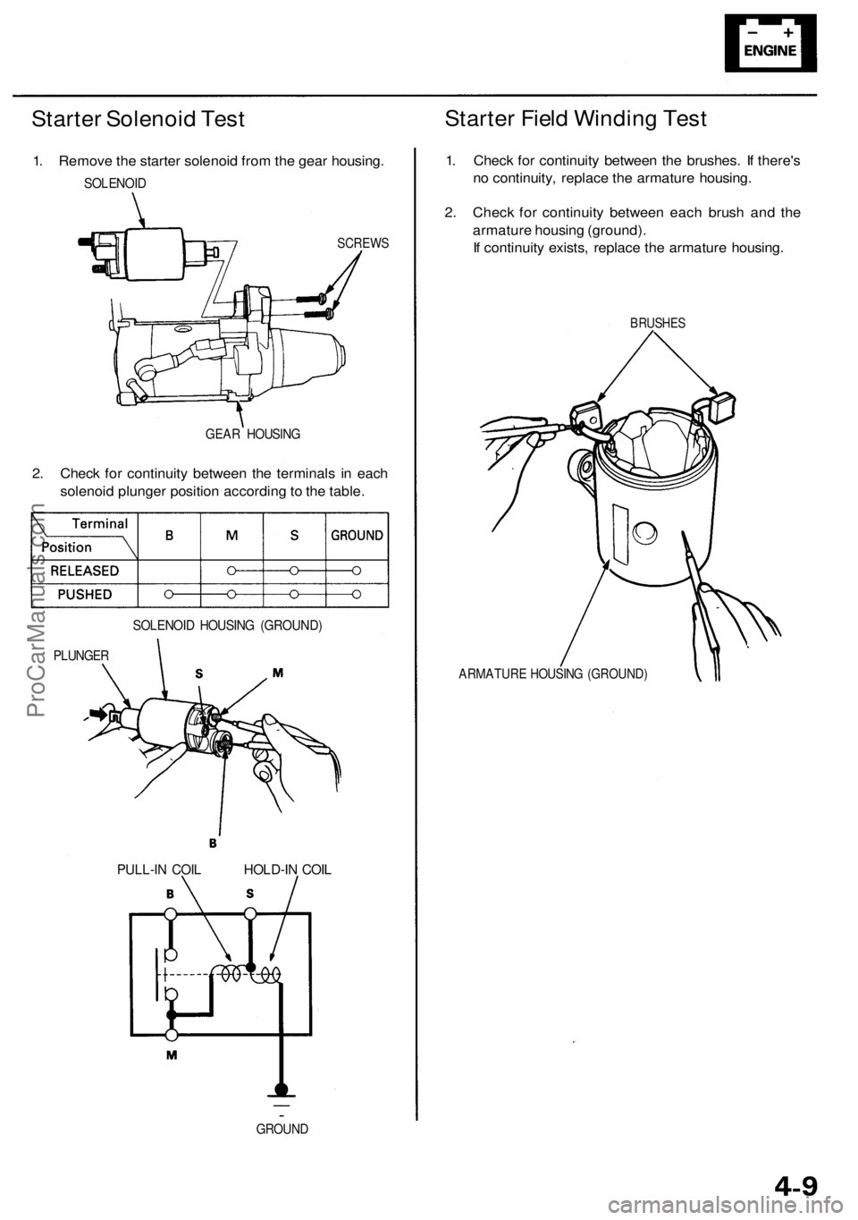
Starter Solenoid Test
1. Remove the starter solenoid from the gear housing.
SOLENOID
SCREWS
GEAR HOUSING
2. Check for continuity between the terminals in each
solenoid plunger position according to the table.
PLUNGER
SOLENOID HOUSING (GROUND)
Starter Field Winding Test
1. Check for continuity between the brushes. If there's
no continuity, replace the armature housing.
2. Check for continuity between each brush and the
armature housing (ground).
If continuity exists, replace the armature housing.
BRUSHES
ARMATURE HOUSING (GROUND)
GROUND
PULL-IN COIL
HOLD-IN COILProCarManuals.com
Page 332 of 1954
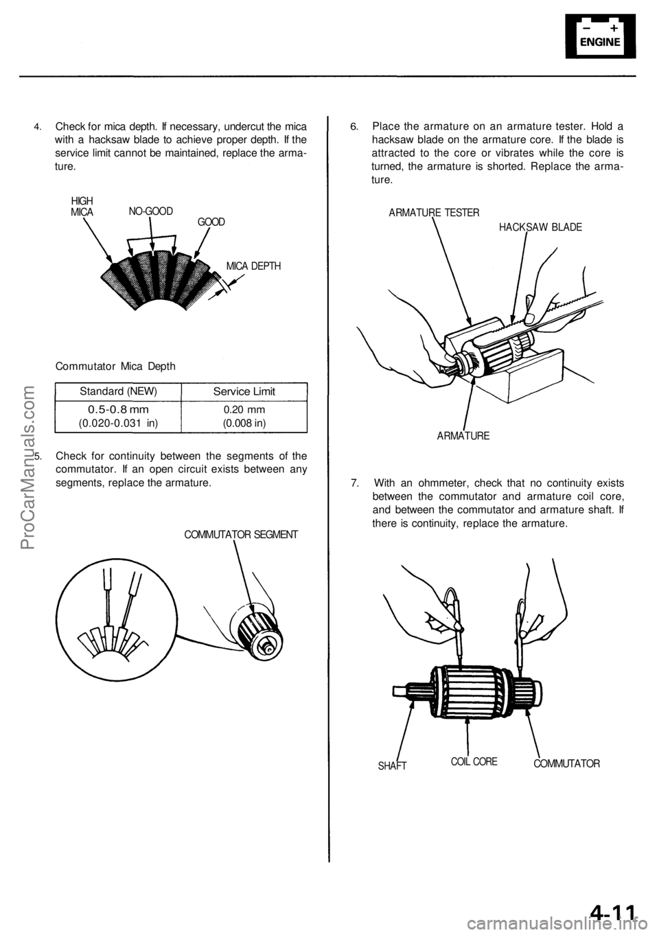
4.
Check for mica depth. If necessary, undercut the mica
with a hacksaw blade to achieve proper depth. If the
service limit cannot be maintained, replace the arma-
ture.
NO-GOOD
GOOD
MICA DEPTH
Commutator Mica Depth
Standard (NEW)
0.5-0.8 mm
(0.020-0.031 in)
Service Limit
0.20
mm
(0.008 in)
5.
Check for continuity between the segments of the
commutator. If an open circuit exists between any
segments, replace the armature.
COMMUTATOR SEGMENT
6.
Place the armature on an armature tester. Hold a
hacksaw blade on the armature core. If the blade is
attracted to the core or vibrates while the core is
turned, the armature is shorted. Replace the arma-
ture.
ARMATURE TESTER
HACKSAW BLADE
ARMATURE
7. With an ohmmeter, check that no continuity exists
between the commutator and armature coil core,
and between the commutator and armature shaft. If
there is continuity, replace the armature.
SHAFT
COIL CORE
COMMUTATOR
HIGH
MICAProCarManuals.com
Page 351 of 1954
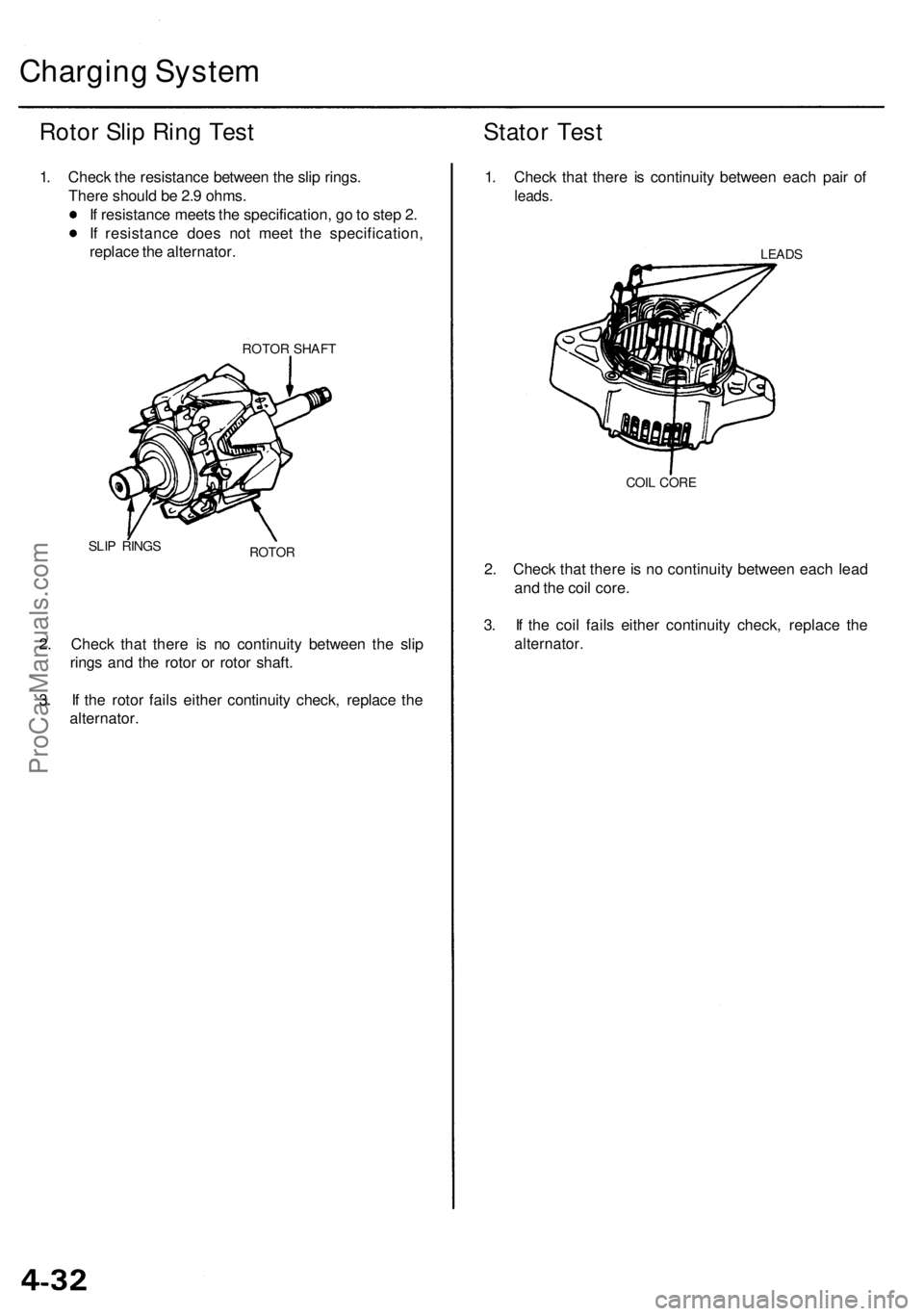
Charging System
Rotor Slip Ring Test
1. Check the resistance between the slip rings.
There should be 2.9 ohms.
If resistance meets the specification, go to step 2.
If resistance does not meet the specification,
replace the alternator.
ROTOR SHAFT
SLIP RINGS
ROTOR
2. Check that there is no continuity between the slip
rings and the rotor or rotor shaft.
3. If the rotor fails either continuity check, replace the
alternator.
Stator Test
1. Check that there is continuity between each pair of
leads.
LEADS
COIL CORE
2. Check that there is no continuity between each lead
and the coil core.
3. If the coil fails either continuity check, replace the
alternator.ProCarManuals.com
Page 411 of 1954
4. Remove the bolts, then remove the camshaft hold-
ers from the cylinder head.
5. Lift the camshaft out of the cylinder head, wipe it
clean, then inspect the lift ramps. Replace the
camshaft if any lobes are pitted, scored, or excessively
worn.
6. Clean the camshaft bearing surfaces in the cylinder
head, then set the camshaft back in place.
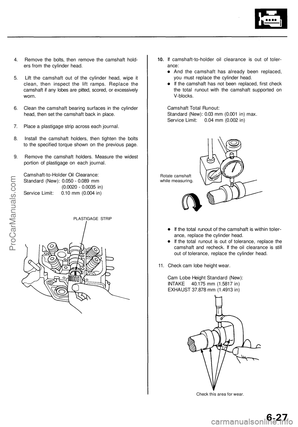
7. Place a plastigage strip across each journal.
8. Install the camshaft holders, then tighten the bolts
to the specified torque shown on the previous page.
9. Remove the camshaft holders. Measure the widest
portion of plastigage on each journal.
PLASTIGAGE STRIP
If camshaft-to-holder oil clearance is out of toler-
ance:
And the camshaft has already been replaced,
you must replace the cylinder head.
If the camshaft has not been replaced, first check
the total runout with the camshaft supported on
V-blocks.
Rotate camshaft
while measuring.
If the total runout of the camshaft is within toler-
ance, replace the cylinder head.
If the total runout is out of tolerance, replace the
camshaft and recheck. If the oil clearance is still
out of tolerance, replace the cylinder head.
11. Check cam lobe height wear.
Check this area for wear.
Cam Lobe Height Standard (New):
INTAKE 40.175 mm (1.5817 in)
EXHAUST 37.878 mm (1.4913 in)
Camshaft Total Runout:
Standard (New): 0.03 mm (0.001 in) max.
Service Limit: 0.04 mm (0.002 in)
Camshaft-to-Holder Oil Clearance:
Standard (New): 0.050 - 0.089 mm
(0.0020 - 0.0035 in)
Service Limit: 0.10 mm (0.004 in)ProCarManuals.com
Page 422 of 1954
Hydraulic Tappets
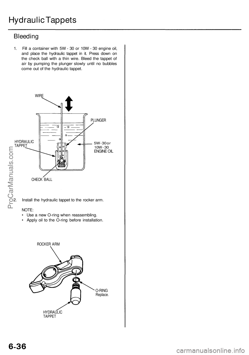
Bleeding
1. Fill a container with 5W - 30 or 10W - 30 engine oil,
and place the hydraulic tappet in it. Press down on
the check ball with a thin wire. Bleed the tappet of
air by pumping the plunger slowly until no bubbles
come out of the hydraulic tappet.
WIRE
HYDRAULIC
TAPPET
PLUNGER
5W
- 30 or
10W
-
30
ENGINE OIL
CHECK BALL
2. Install the hydraulic tappet to the rocker arm.
NOTE:
• Use a new O-ring when reassembling.
• Apply oil to the O-ring before installation.
ROCKER ARM
O-RING
Replace.
HYDRAULIC
TAPPETProCarManuals.com
Page 426 of 1954
Cylinder Heads
Installation (cont'd)
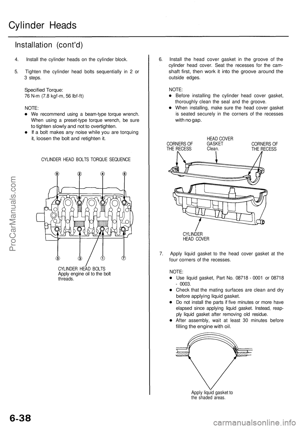
4. Install the cylinder heads on the cylinder block.
5. Tighten the cylinder head bolts sequentially in 2 or
3 steps.
Specified Torque:
76 N-m (7.8 kgf-m, 56 Ibf-ft)
NOTE:
We recommend using a beam-type torque wrench.
When using a preset-type torque wrench, be sure
to tighten slowly and not to overtighten.
If a bolt makes any noise while you are torquing
it, loosen the bolt and retighten it.
CYLINDER HEAD BOLTS TORQUE SEQUENCE
CYLINDER HEAD BOLTS
Apply engine oil to the bolt
threads.
6. Install the head cover gasket in the groove of the
cylinder head cover. Seat the recesses for the cam-
shaft first, then work it into the groove around the
outside edges.
NOTE:
Before installing the cylinder head cover gasket,
thoroughly clean the seal and the groove.
When installing, make sure the head cover gasket
is seated securely in the corners of the recesses
with no gap.
CORNERS OF
THE RECESS
HEAD COVER
GASKET
Clean.
CORNERS OF
THE RECESS
CYLINDER
HEAD COVER
7. Apply liquid gasket to the head cover gasket at the
four corners of the recesses.
NOTE:
Use liquid gasket, Part No. 08718 - 0001 or 08718
- 0003.
Check that the mating surfaces are clean and dry
before applying liquid gasket.
Do not install the parts if five minutes or more have
elapsed since applying liquid gasket. Instead, reap-
ply liquid gasket after removing old residue.
After assembly, wait at least 30 minutes before
filling the engine with oil.
Apply liquid gasket to
the shaded areas.ProCarManuals.com
Page 440 of 1954
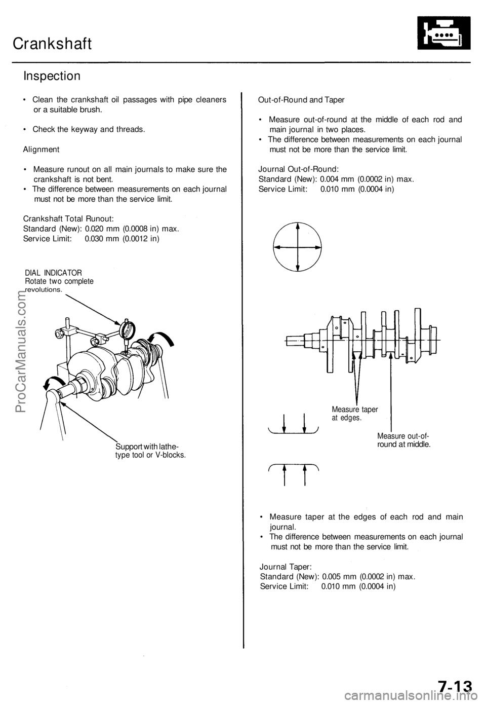
Crankshaft
Inspection
• Clean the crankshaft oil passages with pipe cleaners
or a suitable brush.
• Check the keyway and threads.
Alignment
• Measure runout on all main journals to make sure the
crankshaft is not bent.
• The difference between measurements on each journal
must not be more than the service limit.
Crankshaft Total Runout:
Standard (New): 0.020 mm (0.0008 in) max.
Service Limit: 0.030 mm (0.0012 in)
DIAL INDICATOR
Rotate two complete
revolutions.
Support with lathe-
type tool or V-blocks.
Out-of-Round and Taper
• Measure out-of-round at the middle of each rod and
main journal in two places.
• The difference between measurements on each journal
must not be more than the service limit.
Journal Out-of-Round:
Standard (New): 0.004 mm (0.0002 in) max.
Service Limit: 0.010 mm (0.0004 in)
Measure taper
at edges.
Measure out-of-
round at middle.
• Measure taper at the edges of each rod and main
journal.
• The difference between measurements on each journal
must not be more than the service limit.
Journal Taper:
Standard (New): 0.005 mm (0.0002 in) max.
Service Limit: 0.010 mm (0.0004 in)ProCarManuals.com
Page 454 of 1954
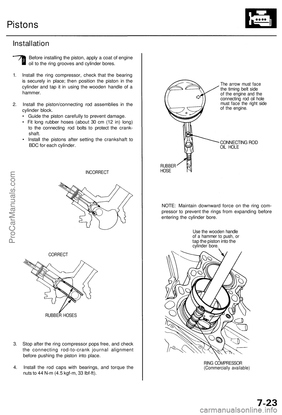
3. Stop after the ring compressor pops free, and check
the connecting rod-to-crank journal alignment
before pushing the piston into place.
4. Install the rod caps with bearings, and torque the
nuts to 44 N-m (4.5 kgf-m, 33 Ibf-ft).
RUBBER HOSES
CORRECT
Pistons
Installation
Before installing the piston, apply a coat of engine
oil to the ring grooves and cylinder bores.
1. Install the ring compressor, check that the bearing
is securely in place; then position the piston in the
cylinder and tap it in using the wooden handle of a
hammer.
2. Install the piston/connecting rod assemblies in the
cylinder block.
• Guide the piston carefully to prevent damage.
• Fit long rubber hoses (about 30 cm (12 in) long)
to the connecting rod bolts to protect the crank-
shaft.
• Install the pistons after setting the crankshaft to
BDC for each cylinder.
INCORRECT
The arrow must face
the timing belt side
of the engine and the
connecting rod oil hole
must face the right side
of the engine.
CONNECTING ROD
OIL HOLE
RUBBER
HOSE
NOTE: Maintain downward force on the ring com-
pressor to prevent the rings from expanding before
entering the cylinder bore.
Use the wooden handle
of a hammer to push, or
tap the piston into the
cylinder bore.
RING COMPRESSOR
(Commercially available)ProCarManuals.com