oil pressure ACURA RL KA9 1996 Service Repair Manual
[x] Cancel search | Manufacturer: ACURA, Model Year: 1996, Model line: RL KA9, Model: ACURA RL KA9 1996Pages: 1954, PDF Size: 61.44 MB
Page 149 of 1954
Random Misfir e
The HD S o r th e sca n too l indicate s Diagnosti c Troubl e Cod e (DTC ) P0300 , an d
som e o f P120 1 - P120 6 o r som e o f P130 1 - P1306 : Rando m misfire .
Descriptio n
Misfire detectio n i s accomplishe d b y monitorin g th e voltag e o f th e spar k plu g wit h th e spar k plu g voltag e senso r whic h i s
buil t i n to th e ignitio n coil .
If misfirin g stron g enoug h t o damag e th e catalys t i s detected , th e MI L wil l blin k durin g th e tim e o f it s occurrence , an d DT C
P0300 , som e
of DTC s P120 1 throug h P1206 or som e of DTC s P130 1 throug h P1306 will be stored . Then , after misfir e has
ceased , th e MI L wil l com e o n an d sta y o n wheneve r th e ignitio n switc h is O N (II) .
I f misfirin g tha t increase s emission s i s detecte d during two consecutiv e drivin g cycles , th e MI L wil l com e on , an d DT C
P0300 , som e o f DTC s P120 1 throug h P120 6 o r som e o f DTC s P130 1 throug h P130 6 wil l b e stored .
NOTE : I f som e o f th e DTC s liste d belo w ar e store d a t th e sam e tim e a s a misfir e DTC , troubleshoo t thos e DTC s first , the n
troubleshoo t th e misfir e DTC .
P1128 , P1129 : MA P senso r
P0171 , P0172 , P0174 , P0175 : Fue l meterin g
P0401 , P0404 , P0406 : EG R syste m
P0345 , P0349 , P0390 , P0394 , P1336 , P1337 , P1386 , P1387 : CKP/CM P (CKP/CYP ) senso r
P0506 , P0507 : Idl e Contro l Syste m
P0511 : IA C valv e
Possibl e Caus e
Fuel pum p insufficien t fue l pressure , amoun t o f flo w
Fue l lin e clogging , blockage , leakag e
Fue l filte r cloggin g
Fue l pressur e regulato r stuc k ope n
EG R syste m malfunctio n
Ignitio n coi l wir e open , leakag e
Ignitio n contro l modul e malfunctio n
IA C valv e malfunctio n
Fas t idl e therm o valv e malfunctio n
Carbo n deposit s o n valve s
Compressio n lo w
Gasolin e doe s no t mee t Owner' s Manua l spec. , lac k o f fue l
Troubleshootin g
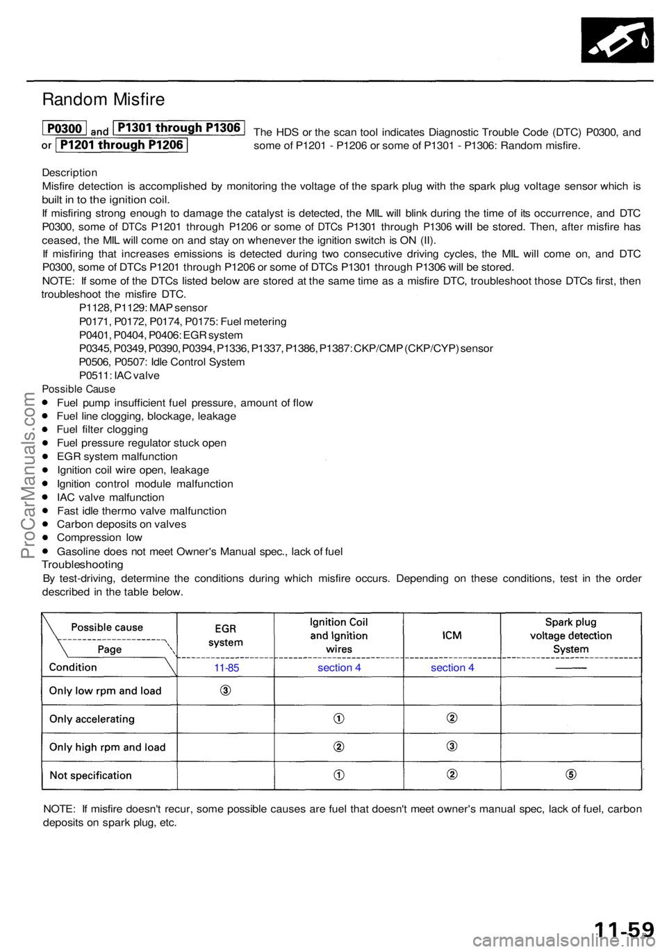
By test-driving , determin e th e condition s during which misfir e occurs . Dependin g o n thes e conditions , tes t i n th e orde r
describe d i n th e tabl e below .
NOTE : I f misfir e doesn' t recur , som e possibl e cause s ar e fue l tha t doesn' t mee t owner' s manua l spec , lac k o f fuel , carbo n
deposit s o n spar k plug , etc .
11-8 5 sectio n 4 section 4
ProCarManuals.com
Page 420 of 1954
Valve Guides
Reaming
NOTE: Fo r ne w valv e guide s only .
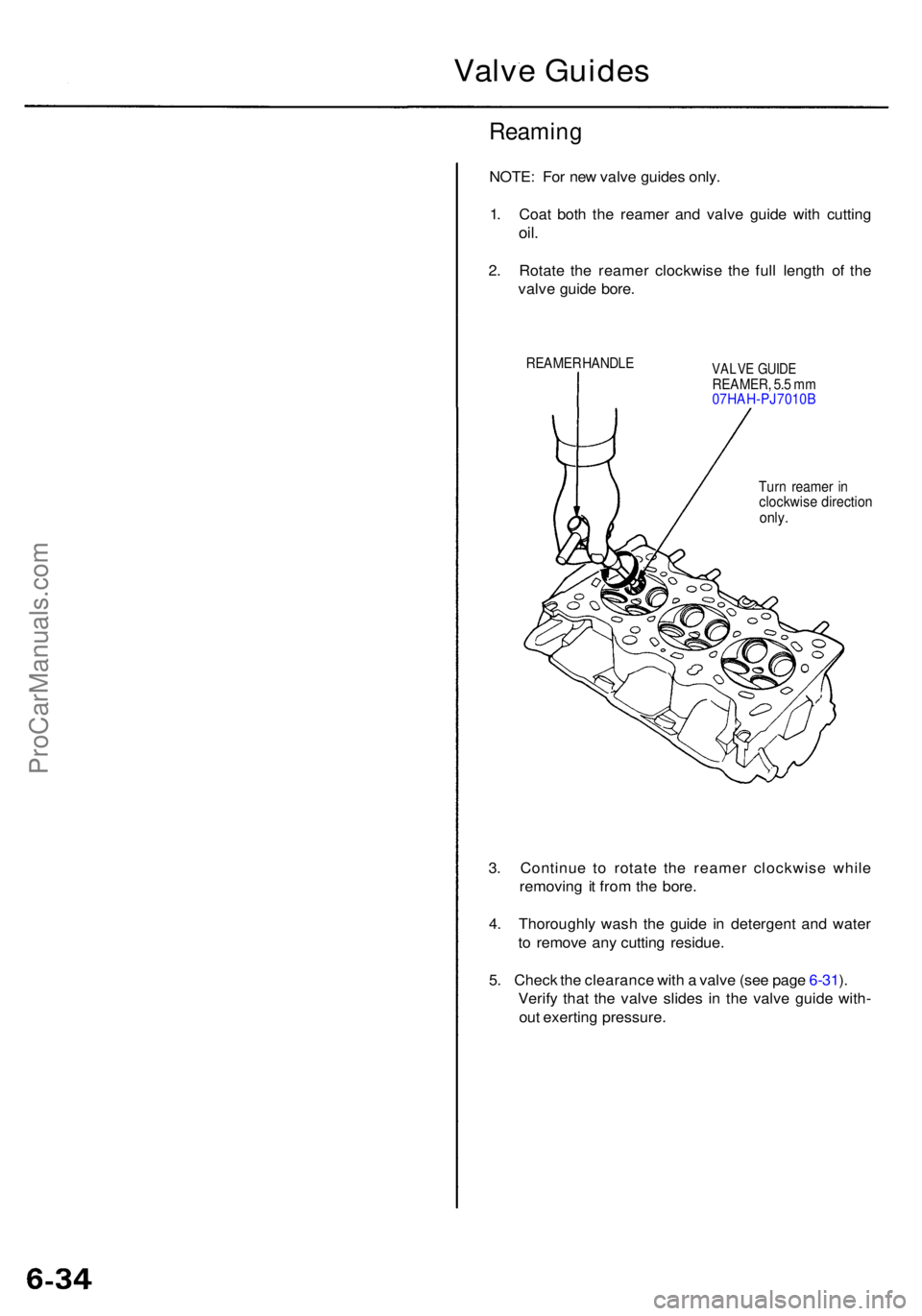
1 . Coa t bot h th e reame r an d valv e guid e wit h cuttin g
oil.
2. Rotat e th e reame r clockwis e th e ful l lengt h o f th e
valv e guid e bore .
REAME R HANDL EVALVE GUID EREAMER , 5. 5 m m
07HAH-PJ7010 B
Tur n reame r i n
clockwis e directio nonly.
3. Continu e t o rotat e th e reame r clockwis e whil e
removin g i t fro m th e bore .
4 . Thoroughl y was h th e guid e i n detergen t an d wate r
t o remov e an y cuttin g residue .
5 . Chec k th e clearanc e wit h a valv e (se e pag e 6-31 ).
Verif y tha t th e valv e slide s i n th e valv e guid e with -
ou t exertin g pressure .
ProCarManuals.com
Page 430 of 1954
Illustrated Index
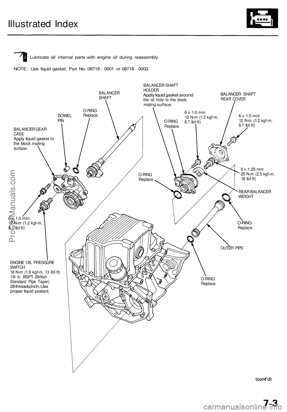
Lubricate all internal parts with engine oil during reassembly.
NOTE: Use liquid gasket, Part No. 08718 - 0001 or 08718 - 0003.
BALANCER
SHAFT
O-RING
Replace.
DOWEL
PIN
BALANCER GEAR
CASE
Apply liquid gasket to
the block mating
surface.
BALANCER SHAFT
HOLDER
Apply liquid gasket around
the oil hole to the block
mating surface.
O-RING
Replace.
6 x 1.0 mm
12 N-m (1.2 kgf-m,
8.7 Ibf-ft)
BALANCER SHAFT
REAR COVER
6 x 1.0 mm
12 N-m (1.2 kgf-m,
8.7 Ibf-ft)
8 x
1.25
mm
25 N-m (2.5 kgf-m,
18 Ibf-ft)
REAR BALANCER
WEIGHT
O-RING
Replace.
OUTER PIPE
O-RING
Replace.
ENGINE OIL PRESSURE
SWITCH
18 N-m (1.8 kgf-m, 13 Ibf-ft)
1/8 in. BSPT (British
Standard Pipe Taper)
28 threads/inch. Use
proper liquid sealant.
6 x 1.0 mm
12 N-m (1.2 kgf-m,
8.7 Ibf-ft)
O-RING
Replace.ProCarManuals.com
Page 469 of 1954
3. I f th e switc h fail s t o operate , chec k th e engin e oi l
level . I f th e engin e oi l leve l i s OK , chec k th e engin e
oi l pressure .
YEL/RED WIR E(Covere d wit hinsulation )
Testing
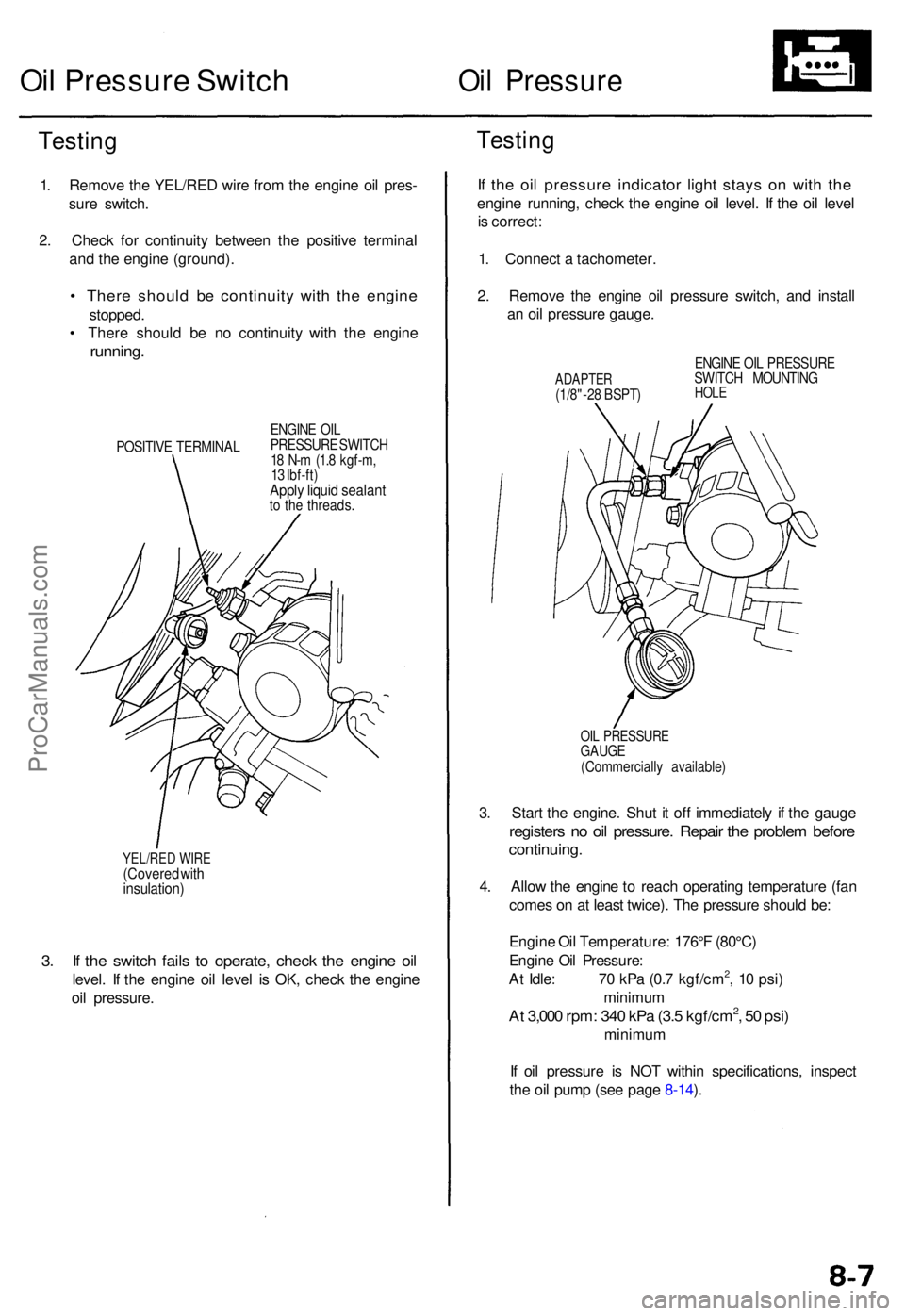
1. Remov e th e YEL/RE D wir e fro m th e engin e oi l pres -
sur e switch .
2 . Chec k fo r continuit y betwee n th e positiv e termina l
an d th e engin e (ground) .
• Ther e shoul d b e continuit y wit h th e engin e
stopped .
• Ther e shoul d b e n o continuit y wit h th e engin e
running .
POSITIV E TERMINA LENGIN
E OI L
PRESSUR E SWITC H
1 8 N- m (1. 8 kgf-m ,
1 3 Ibf-ft )
Apply liqui d sealan tto th e threads .
Oil Pressur e Switc hOil Pressur e
Testing
If th e oi l pressur e indicato r ligh t stay s o n wit h th e
engin e running , chec k th e engin e oi l level . I f th e oi l leve l
i s correct :
1 . Connec t a tachometer .
2 . Remov e th e engin e oi l pressur e switch , an d instal l
a n oi l pressur e gauge .
ADAPTE R(1/8"-28 BSPT ) ENGIN
E OI L PRESSUR E
SWITC H MOUNTIN GHOLE
OIL PRESSUR EGAUGE(Commerciall y available )
3. Star t th e engine . Shu t i t of f immediatel y i f th e gaug e
register s n o oi l pressure . Repai r th e proble m befor e
continuing .
4. Allo w th e engin e to reac h operatin g temperatur e (fa n
come s o n a t leas t twice) . Th e pressur e shoul d be :
Engin e Oi l Temperature : 176° F (80°C )
Engin e Oi l Pressure :
A t Idle : 7 0 kP a (0. 7 kgf/cm
2, 1 0 psi )
minimu m
At 3,00 0 rpm : 34 0 kP a (3. 5 kgf/cm2, 5 0 psi )
minimu m
I f oi l pressur e i s NO T withi n specifications , inspec t
th e oi l pum p (se e pag e 8-14 ).
ProCarManuals.com
Page 492 of 1954
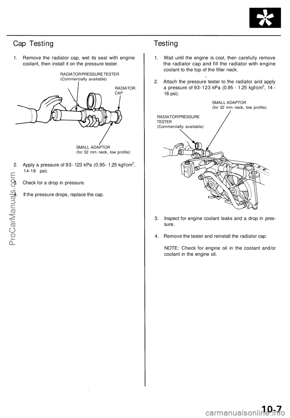
Cap Testing
Testing
1. Remove the radiator cap, wet its seal with engine
coolant, then install it on the pressure tester.
RADIATOR
CAP
2. Apply a pressure of 93- 123 kPa (0.95- 1.25 kgf/cm2,
14-18 psi).
3. Check for a drop in pressure.
4. If the pressure drops, replace the cap.
1. Wait until the engine is cool, then carefully remove
the radiator cap and fill the radiator with engine
coolant to the top of the filler neck.
2. Attach the pressure tester to the radiator and apply
a pressure of 93-123 kPa (0.95 - 1.25 kgf/cm2, 14 -
18
psi).
RADIATOR PRESSURE
TESTER
(Commercially available)
3. Inspect for engine coolant leaks and a drop in pres-
sure.
4. Remove the tester and reinstall the radiator cap.
NOTE: Check for engine oil in the coolant and/or
coolant in the engine oil.
RADIATOR PRESSURE TESTER
(Commercially available)
SMALL ADAPTOR
(for 32 mm neck, low profile)
SMALL ADAPTOR
(for 32 mm neck, low profile)ProCarManuals.com
Page 498 of 1954
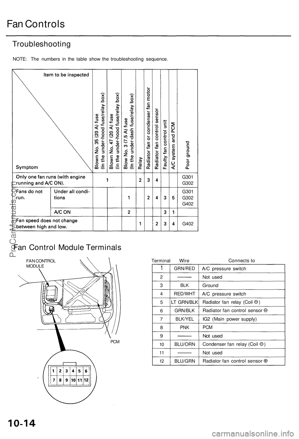
Fan Controls
Troubleshooting
NOTE: The numbers in the table show the troubleshooting sequence.
G301
G302
G301
G302
G402
G402
Fan Control Module Terminals
FAN CONTROL
MODULE
Terminal Wire
Connects to
1
2
3
4
5
6
7
8
9
10
11
12
GRN/RED
BLK
RED/WHT
LT GRN/BLK
GRN/BLK
BLK/YEL
PNK
BLU/ORN
BLU/GRN
A/C pressure switch
Not used
Ground
A/C pressure switch
Radiator fan relay (Coil )
Radiator fan control sensor
IG2 (Main power supply)
PCM
Not used
Condenser fan relay (Coil )
Not used
Radiator fan control sensor
PCMProCarManuals.com
Page 599 of 1954
PGM-FI Syste m
Rando m Misfir e
The sca n too l indicate s Diagnosti c Troubl e Cod e (DTC ) P0300*3,
P1300*4 an d som e o f P120 1 - P120 6 o r som e o f P130 1 - P1306 :
Rando m misfire .
Descriptio n
Misfir e detectio n i s accomplishe d b y monitorin g th e voltag e o f th e spar k plu g wit h th e spar k plu g voltag e senso r whic h i s
buil t i n to th e ignitio n coil .
If misfirin g stron g enoug h t o damag e th e catalys t i s detected , th e MI L wil l blin k durin g th e tim e o f it s occurrence , an d DT C
P1300*3 o r P0300*4, som e o f DTC s P120 1 throug h P120 6 o r som e o f DTC s P130 1 throug h P130 6 wil l b e stored . Then , afte r
misfir e ha s ceased , th e MI L wil l com e o n an d sta y o n wheneve r th e ignitio n switc h i s O N (II) .
I f misfirin g tha t increase s emission s i s detecte d durin g tw o consecutiv e drivin g cycles , th e MI L wil l com e on , an d DT C
P1300*
3 o r P0300*4, som e o f DTC s P120 1 throug h P120 6 o r som e o f DTC s P130 1 throug h P130 6 wil l b e stored .
NOTE : I f som e o f th e DTC s liste d belo w ar e store d a t th e sam e tim e a s a misfir e DTC , troubleshoo t thos e DTC s first , the n
troubleshoo t th e misfir e DTC .
P0106*1, P1128*2, P1129*2: MA P senso r
P0171 , P0172 , P0174 , P0175 : Fue l meterin g
P0401 , P1491 , PU98 : EG R syste m
P0335 , P0336 , P1336 , P1337 , P1381 , P1382 , P1386 , P1387 : CKP/CY P senso r
P0505 : Idl e Contro l Syste m
PI508 : IA C valv e
*1 : '9 6 mode l onl y
*2 : '9 7 - 0 1 model s
*3: '9 6 - 9 7 model s
*4: '9 8 - 0 1 model s
Possibl e Caus e
Fuel pum p insufficien t fue l pressure , amoun t o f flo w
Fue l lin e clogging , blockage , leakag e
Fue l filte r cloggin g
Fue l pressur e regulato r stuc k ope n
EG R syste m malfunctio n
Ignitio n coi l wir e open , leakag e
Ignition contro l modul e malfunction
MA P senso r range/performance , poo r response*1
IA C valv e malfunctio n
Fas t idl e therm o valv e malfunctio n
Carbo n deposit s o n valve s
Compressio n lo w
Gasolin e doe s no t mee t Owner' s Manua l spec. , lac k o f fue l
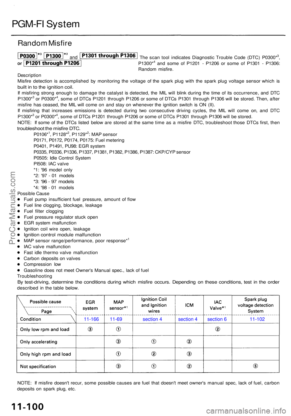
Troubleshootin g
By test-driving , determin e th e condition s durin g whic h misfir e occurs . Dependin g o n thes e conditions , tes t i n th e orde r
describe d i n th e tabl e below .
NOTE : I f misfir e doesn' t recur , som e possibl e cause s ar e fue l tha t doesn' t mee t owner' s manua l spec , lac k o f fuel , carbo n
deposit s o n spar k plug , etc .
11-166 11-69 section 4 section 4 section 6 11-102
and
ProCarManuals.com
Page 634 of 1954
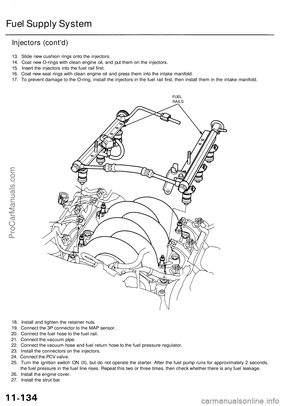
Fuel Supply System
Injectors (cont'd)
13. Slide new cushion rings onto the injectors.
14. Coat new O-rings with clean engine oil, and put them on the injectors.
15. Insert the injectors into the fuel rail first.
16. Coat new seal rings with clean engine oil and press them into the intake manifold.
17. To prevent damage to the O-ring, install the injectors in the fuel rail first, then install them in the intake manifold.
FUEL
RAILS
18. Install and tighten the retainer nuts.
19. Connect the 3P connector to the MAP sensor.
20. Connect the fuel hose to the fuel rail.
21. Connect the vacuum pipe.
22. Connect the vacuum hose and fuel return hose to the fuel pressure regulator.
23. Install the connectors on the injectors.
24. Connect the PCV valve.
25. Turn the ignition switch ON (II), but do not operate the starter. After the fuel pump runs for approximately 2 seconds,
the fuel pressure in the fuel line rises. Repeat this two or three times, then check whether there is any fuel leakage.
26. Install the engine cover.
27. Install the strut bar.ProCarManuals.com
Page 873 of 1954
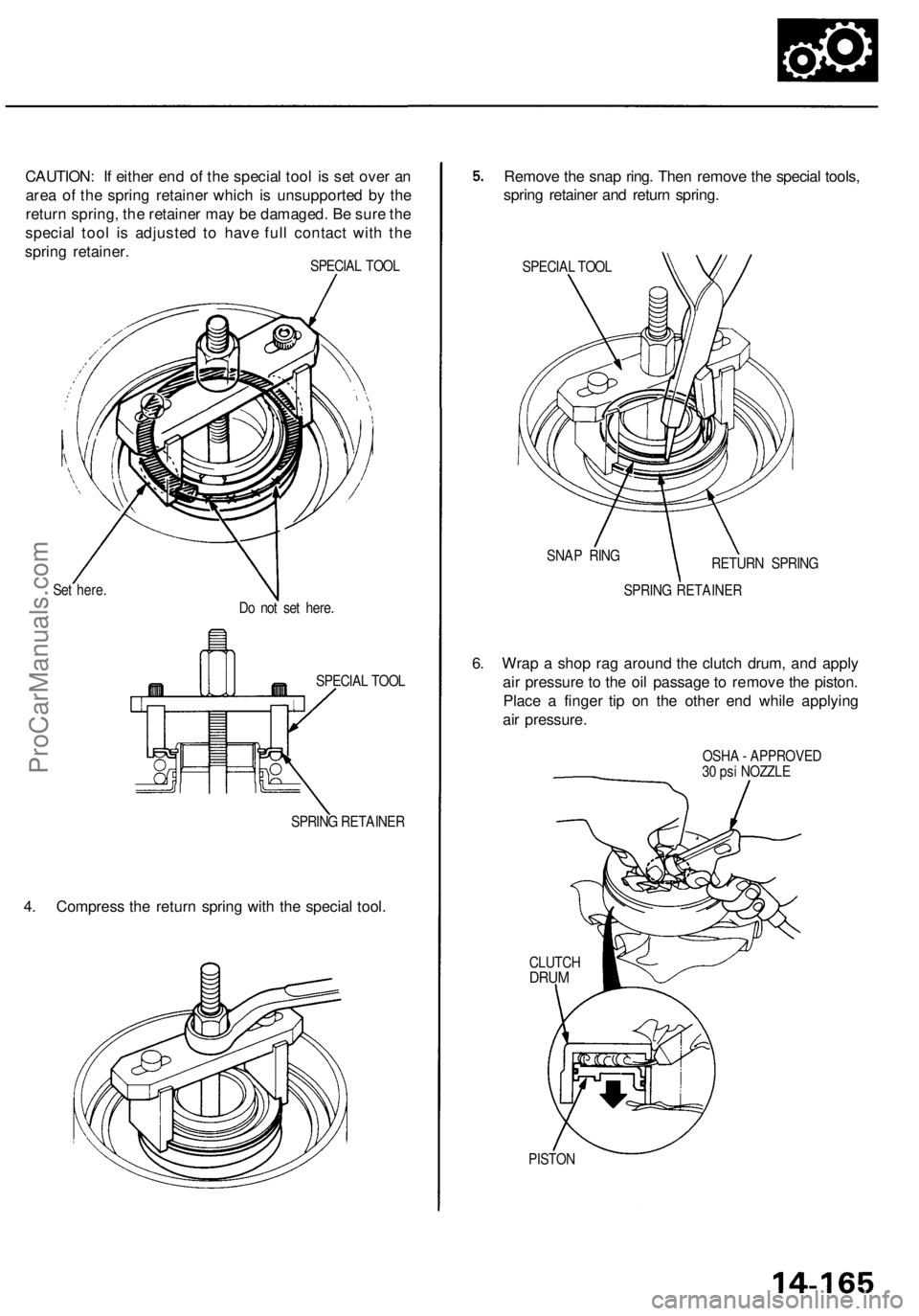
CAUTION: If either end of the special tool is set over an
area of the spring retainer which is unsupported by the
return spring, the retainer may be damaged. Be sure the
special tool is adjusted to have full contact with the
spring retainer.
Set here.
SPECIAL TOOL
SPRING RETAINER
4. Compress the return spring with the special tool.
Remove the snap ring. Then remove the special tools,
spring retainer and return spring.
SPECIAL TOOL
SNAP RING
SPRING RETAINER
6. Wrap a shop rag around the clutch drum, and apply
air pressure to the oil passage to remove the piston.
Place a finger tip on the other end while applying
air pressure.
CLUTCH
DRUM
PISTON
OSHA - APPROVED
30 psi NOZZLE
Do not set here.
SPECIAL TOOL
RETURN SPRINGProCarManuals.com
Page 1156 of 1954
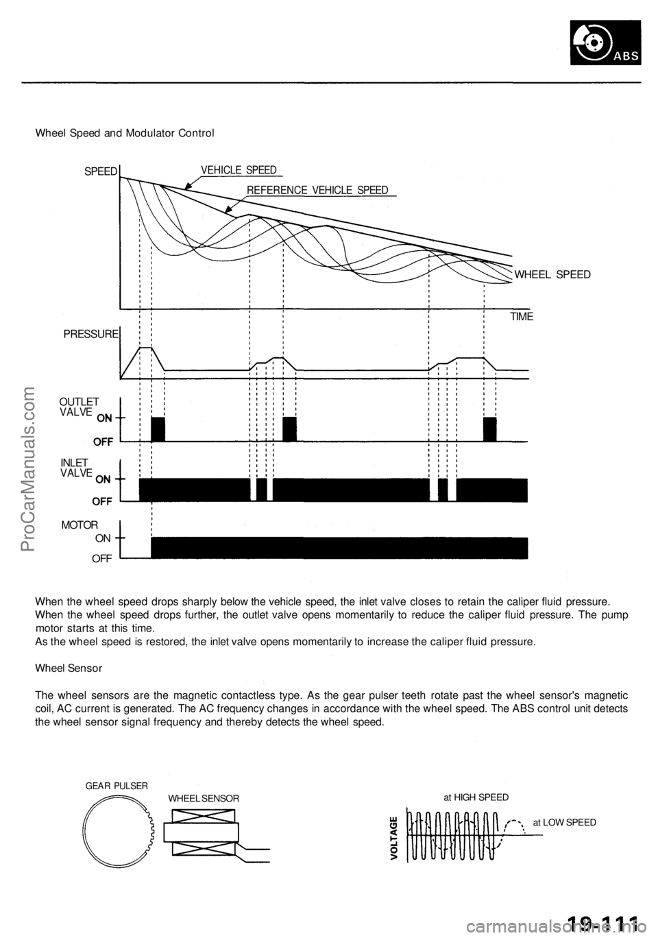
Wheel Spee d an d Modulato r Contro l
SPEED VEHICL E SPEE D
REFERENC E VEHICL E SPEE D
PRESSUR E
OUTLETVALVE
INLETVALV E
MOTO R
ON
OF F
WHEE L SPEE D
TIM E
Whe n th e whee l spee d drop s sharpl y belo w th e vehicl e speed , th e inle t valv e close s t o retai n th e calipe r flui d pressure .
Whe n th e whee l spee d drop s further , th e outle t valv e open s momentaril y t o reduc e th e calipe r flui d pressure . Th e pum p
moto r start s a t thi s time .
A s th e whee l spee d i s restored , th e inle t valv e open s momentaril y t o increas e th e calipe r flui d pressure .
Whee l Senso r
Th e whee l sensor s ar e th e magneti c contactles s type . A s th e gea r pulse r teet h rotat e pas t th e whee l sensor' s magnetic
coil , A C curren t i s generated . Th e A C frequenc y change s i n accordanc e wit h th e whee l speed . Th e AB S contro l uni t detect s
th e whee l senso r signa l frequenc y an d thereb y detect s th e whee l speed .
GEAR PULSE R
WHEEL SENSO R a
t HIG H SPEE D
at LO W SPEE D
ProCarManuals.com