phone ACURA RL KA9 1996 Service Repair Manual
[x] Cancel search | Manufacturer: ACURA, Model Year: 1996, Model line: RL KA9, Model: ACURA RL KA9 1996Pages: 1954, PDF Size: 61.44 MB
Page 43 of 1954
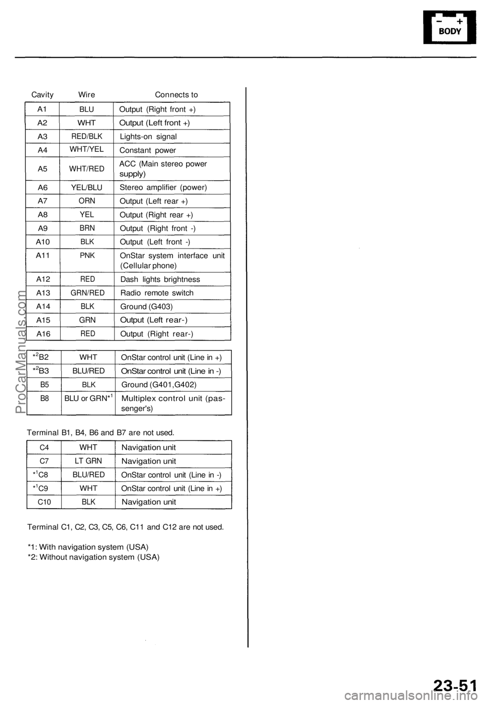
Cavity
Wire
Connects to
A1
A2
A3
A4
A5
A6
A7
A8
A9
A10
A11
A12
A13
A14
A15
A16
BLU
WHT
RED/BLK
WHT/YEL
WHT/RED
YEL/BLU
ORN
YEL
BRN
BLK
PNK
RED
GRN/RED
BLK
GRN
RED
Output (Right front +)
Output (Left front +)
Lights-on signal
Constant power
ACC (Main stereo power
supply)
Stereo amplifier (power)
Output (Left rear +)
Output (Right rear +)
Output (Right front -)
Output (Left front -)
OnStar system interface unit
(Cellular phone)
Dash lights brightness
Radio remote switch
Ground (G403)
Output (Left rear-)
Output (Right rear-)
*2B2
*2B3
B5
B8
WHT
BLU/RED
BLK
BLU or GRN*1
OnStar control unit (Line in +)
OnStar control unit (Line in -)
Ground (G401,G402)
Multiplex control unit (pas-
senger's)
Terminal B1, B4, B6 and B7 are not used.
C4
C7
*1C8
*1C9
C10
WHT
LT GRN
BLU/RED
WHT
BLK
Navigation unit
Navigation unit
OnStar control unit (Line in -)
OnStar control unit (Line in +)
Navigation unit
Terminal C1, C2, C3, C5, C6, C11 and C12 are not used.
*1: With navigation system (USA)
*2: Without navigation system (USA)ProCarManuals.com
Page 44 of 1954
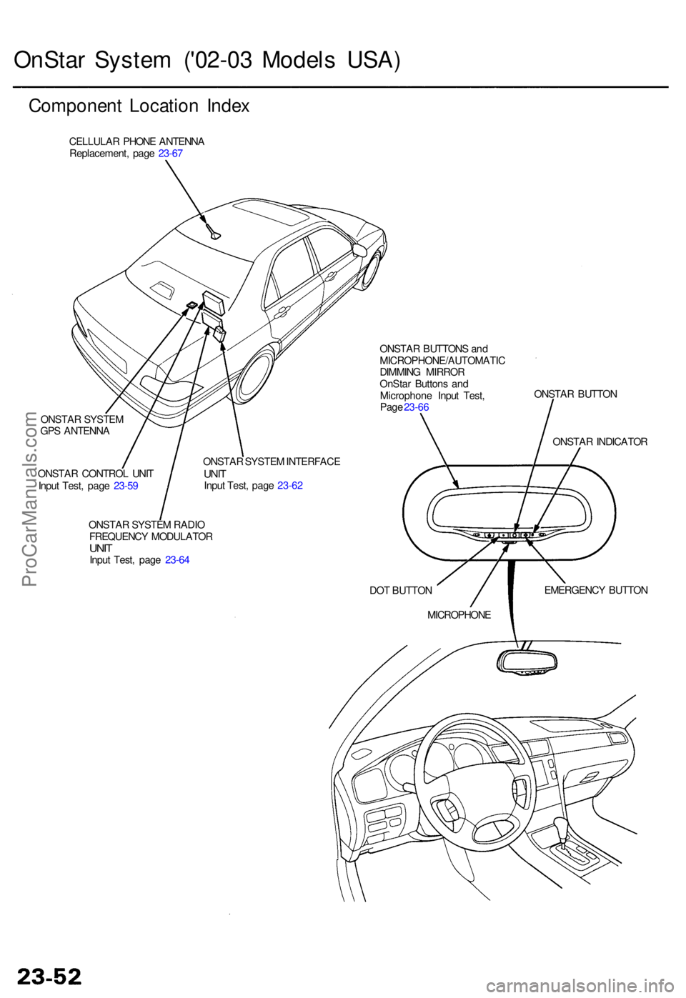
OnStar Syste m ('0 2-03 Mode ls USA )
Componen t Locatio n Inde x
CELLULA R PHON E ANTENN A
Replacement , pag e 23-6 7
ONSTA R SYSTE M
GP S ANTENN A
ONSTA R CONTRO L UNI T
Inpu t Test , pag e 23-5 9 ONSTA
R SYSTE M INTERFAC E
UNITInpu t Test , pag e 23-6 2
ONSTA R SYSTE M RADI O
FREQUENC Y MODULATO R
UNITInpu t Test , pag e 23-6 4 ONSTA
R BUTTON S an d
MICROPHONE/AUTOMATI C
DIMMIN G MIRRO R
OnSta r Button s an d
Microphon e Inpu t Test ,
Pag e 23-6 6 ONSTA
R BUTTO N
DO T BUTTO N
MICROPHON E EMERGENC
Y BUTTO N
ONSTA
R INDICATO R
ProCarManuals.com
Page 45 of 1954

Description
Basic operation:
1. OnStar system is activated.
2. Data is transmitted to service provider.
GPS SATELLITES
Two-way cellular communication
with call center.
Dispatch
Rescue/Police
911 CALL
CENTER
3. Call center associate makes appropriate response:
— Accident/Emergency notification (Police, Fire and EMS, etc.)
— Airbag deployment (Accident)
— Roadside assistance
— Stolen vehicle tracking
— Remote door lock/unlock command
— Misplaced vehicle (Flashes parking lights/honks horn)
— Route guidance
— Ride Assist
— Concierge services/convenience
Buttons and indicator:
DOT BUTTON
ONSTAR INDICATOR
Solid Green Light: System OK
Flashing Green Light: Call in
progress
Solid Red Light: System
malfunction
Flashing Red Light: Call
in progress, but malfunction
in system exist.
ONSTAR BUTTON
EMERGENCY BUTTON
Activation and termination
of voice recognition
(VR) for virtual advisor and cellular phone.
Used to connect to call
center (voice based information
service).
Used for emergencies.
Emergency calls have priority
over all others.
ONSTAR CALL
CENTER
(Human Advisor)
Requests for
dispatchProCarManuals.com
Page 46 of 1954
OnStar Syste m ('0 2 Mode l USA )
Descriptio n (cont'd )
Stolen vehicl e tracking :
If th e vehicl e i s stolen , th e owne r ca n repor t i t t o th e cal l center . The y wil l notif y th e authoritie s an d trac k th e vehicl e loca -
tio n t o assis t i n recovery .
Virtual advisor :
1. Virtua l adviso r setup . A subscribe r set s u p a persona l profil e o n thei r hom e compute r throug h th e interne t a t th e
OnSta r we b site .
— Stoc k portfoli o
— Traffi c
— Sport s
— New s
— Weather
— E-mai l
2 . Subscribe r call s OnSta r cal l center .
3 . OnSta r receive s an d processe s request .
4 . Profil e accesse d fo r requeste d information .
5 . OnSta r send s informatio n bac k t o subscriber . A compute r voic e relay s th e requeste d information .
Cellular phone :
The use r can mak e a hands-fre e cellula r phon e cal l wit h on e touc h (b y pressin g th e "dot " button) , an d b y usin g voic e
recognitio n commands .
Remote operation :
Vehicle door s ca n b e locke d remotel y if forgotte n o r unlocke d whe n key s ar e accidentall y lef t insid e th e vehicle . I f th e vehi -
cl e is misplace d in a parkin g lot , vehicl e aler t (honk s th e hor n an d Flashe s th e parkin g lights ) ca n b e requeste d remotely .
NOTE : Durin g norma l vehicl e operation , th e syste m is i n hig h powe r mode . Afte r th e ignitio n switc h i s turne d OF F th e sys -
te m wil l g o int o lo w powe r mod e fo r 4 8 hours , afte r tha t th e syste m wil l switc h t o slee p mod e t o conserv e batter y power .
Whe n
in lo w powe r mode , the syste m will switc h back to th e hig h powe r mod e for 1 minut e out o f ever y 10 minute s for a
perio d o f 4 8 hours . Remot e operatio n is onl y availabl e durin g th e 1 minut e perio d o f hig h powe r operation . Whe n th e sys -
te m is i n slee p mode , remot e operatio n i s no t possible .
Registerin g replacemen t components :
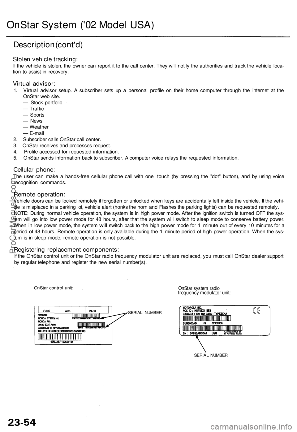
If th e OnSta r contro l uni t o r th e OnSta r radi o frequenc y modulato r uni t ar e replaced , yo u mus t cal l OnSta r deale r suppor t
b y regula r telephon e an d registe r th e ne w seria l number(s) .
OnStar contro l unit :OnSta r syste m radi ofrequenc y modulato r unit :
SERIA L NUMBE R
SERIAL NUMBE R
ProCarManuals.com
Page 47 of 1954
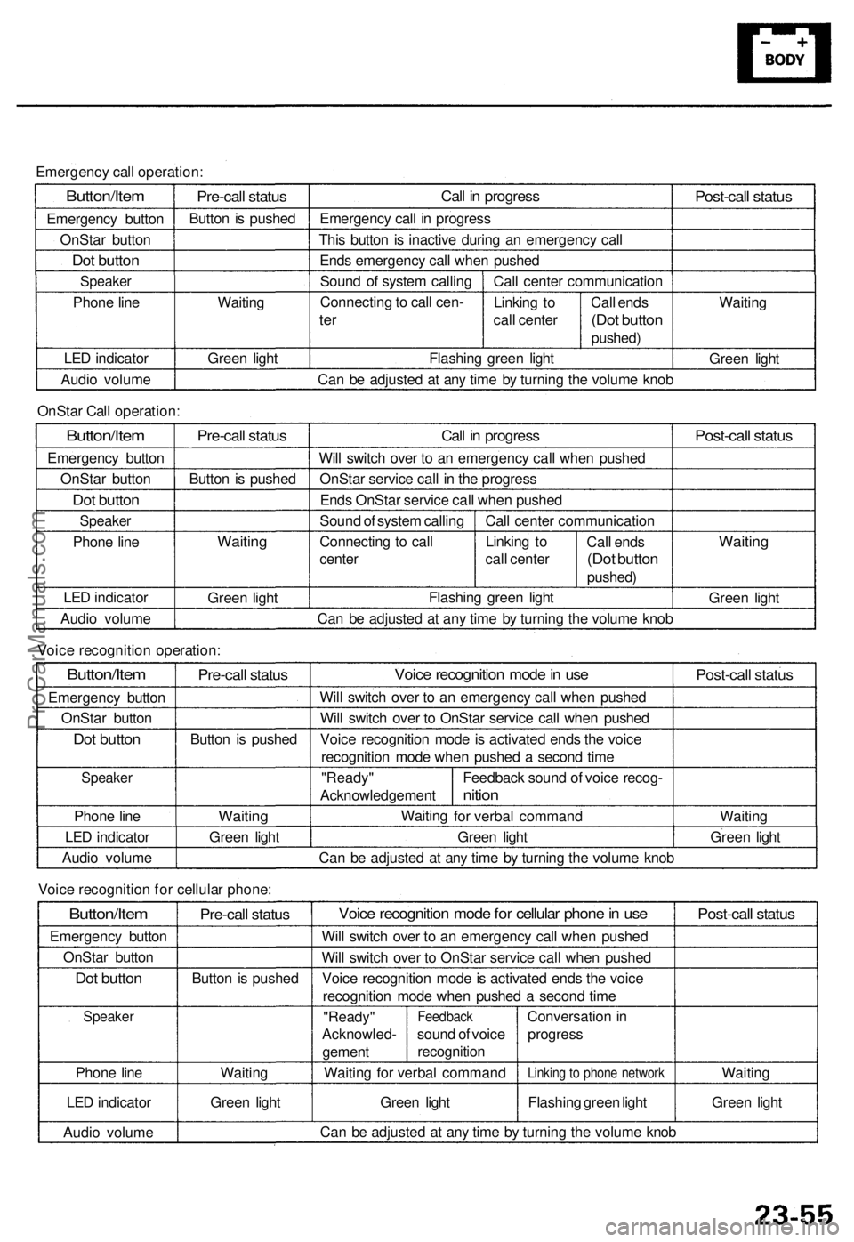
Emergency call operation:
Button/Item
Emergency button
OnStar button
Dot button
Speaker
Phone line
LED indicator
Audio volume
Pre-call status
Button is pushed
Waiting
Green light
Call in progress
Emergency call in progress
This button is inactive during an emergency call
Ends emergency call when pushed
Sound of system calling
Connecting to call cen-
ter
Call center communication
Linking to
call center
Flashing green light
Call ends
(Dot button
pushed)
Post-call status
Waiting
Green light
Can be adjusted at any time by turning the volume knob
OnStar Call operation:
Button/Item
Emergency button
OnStar button
Dot button
Speaker
Phone line
LED indicator
Audio volume
Pre-call status
Button is pushed
Waiting
Green light
Call in progress
Will switch over to an emergency call when pushed
OnStar service call in the progress
Ends OnStar service call when pushed
Sound of system calling
Connecting to call
center
Call center communication
Linking to
call center
Call ends
(Dot button
pushed)
Flashing green light
Post-call status
Waiting
Green light
Can be adjusted at any time by turning the volume knob
Voice recognition operation:
Button/Item
Emergency button
OnStar button
Dot button
Speaker
Phone line
LED indicator
Audio volume
Pre-call status
Button is pushed
Waiting
Green light
Voice recognition mode in use
Will switch over to an emergency call when pushed
Will switch over to OnStar service call when pushed
Voice recognition mode is activated ends the voice
recognition mode when pushed a second time
"Ready"
Acknowledgement
Waiting
Feedback sound of voice recog-
nition
for verbal command
Green light
Post-call status
Waiting
Green light
Can be adjusted at any time by turning the volume knob
Voice recognition for cellular phone:
Button/Item
Emergency button
OnStar button
Dot button
Speaker
Phone line
LED indicator
Audio volume
Pre-call status
Button is pushed
Waiting
Green light
Voice recognition mode for cellular phone in use
Will switch over to an emergency call when pushed
Will switch over to OnStar service call when pushed
Voice recognition mode is activated ends the voice
recognition mode when pushed a second time
"Ready"
Acknowled-
gement
Feedback
sound of voice
recognition
Waiting for verbal command
Green light
Conversation in
progress
Linking to phone network
Flashing green light
Post-call status
Waiting
Green light
Can be adjusted at any time by turning the volume knobProCarManuals.com
Page 50 of 1954
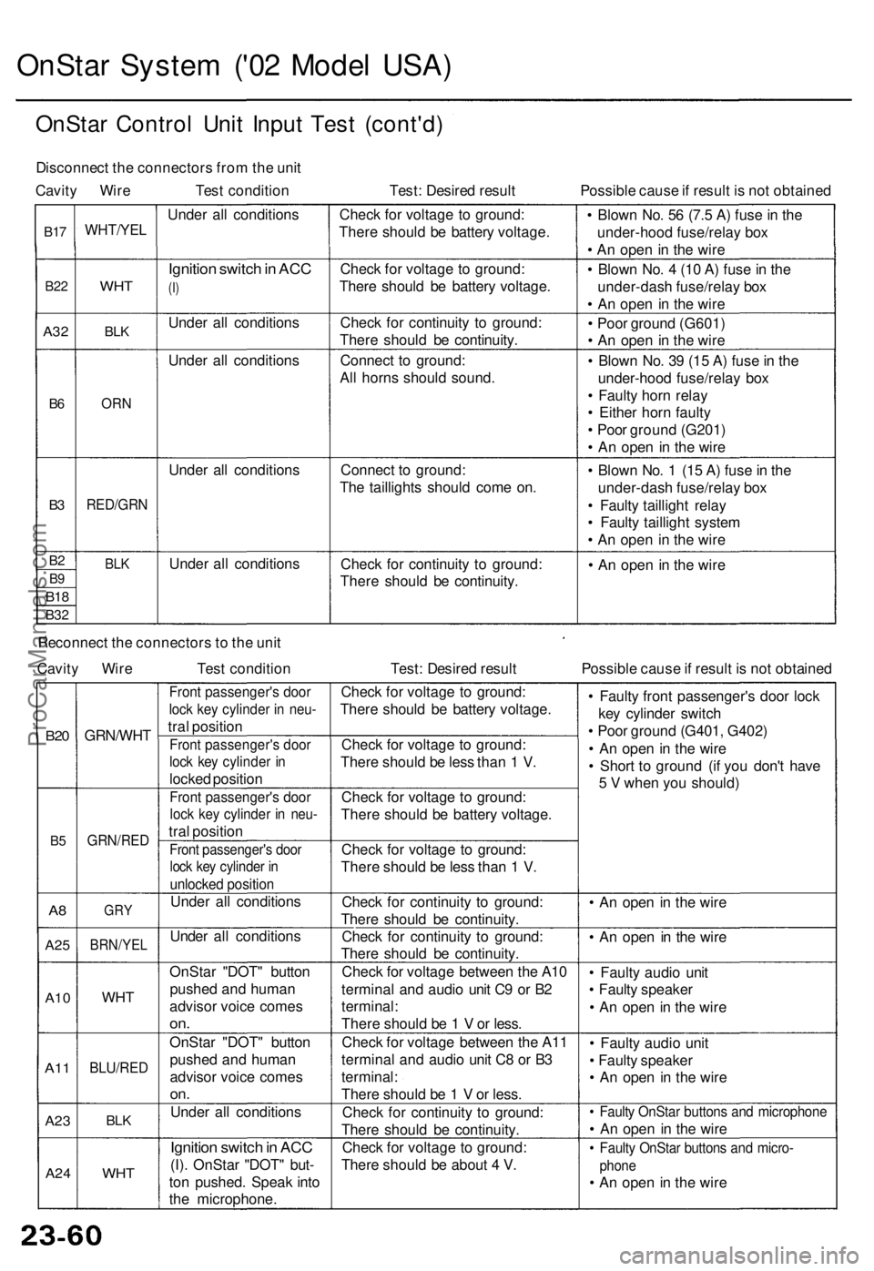
OnStar System ('02 Model USA)
OnStar Control Unit Input Test (cont'd)
Disconnect the connectors from the unit
Cavity Wire Test condition
Test: Desired result
Possible cause if result is not obtained
B17
B22
A32
B6
B3
B2
B9
B18
B32
WHT/YEL
WHT
BLK
ORN
RED/GRN
BLK
Under all conditions
Ignition switch in ACC
(I)
Under all conditions
Under all conditions
Under all conditions
Under all conditions
Check for voltage to ground:
There should be battery voltage.
Check for voltage to ground:
There should be battery voltage.
Check for continuity to ground:
There should be continuity.
Connect to ground:
All horns should sound.
Connect to ground:
The taillights should come on.
Check for continuity to ground:
There should be continuity.
• Blown No. 56 (7.5 A) fuse in the
under-hood fuse/relay box
• An open in the wire
• Blown No. 4 (10 A) fuse in the
under-dash fuse/relay box
• An open in the wire
• Poor ground (G601)
• An open in the wire
• Blown No. 39 (15 A) fuse in the
under-hood fuse/relay box
• Faulty horn relay
• Either horn faulty
• Poor ground (G201)
• An open in the wire
• Blown No. 1 (15 A) fuse in the
under-dash fuse/relay box
• Faulty taillight relay
• Faulty taillight system
• An open in the wire
• An open in the wire
Reconnect the connectors to the unit
Cavity Wire
Test condition
Test: Desired result
Possible cause if result is not obtained
B20
B5
A8
A25
A10
A11
A23
A24
GRN/WHT
GRN/RED
GRY
BRN/YEL
WHT
BLU/RED
BLK
WHT
Front passenger's door
lock key cylinder in neu-
tral position
Front passenger's door
lock key cylinder in
locked position
Front passenger's door
lock key cylinder in neu-
tral position
Front passenger's door
lock key cylinder in
unlocked position
Under all conditions
Under all conditions
OnStar "DOT" button
pushed and human
advisor voice comes
on.
OnStar "DOT" button
pushed and human
advisor voice comes
on.
Under all conditions
Ignition switch in ACC
(I). OnStar "DOT" but-
ton pushed. Speak into
the microphone.
Check for voltage to ground:
There should be battery voltage.
Check for voltage to ground:
There should be less than 1 V.
Check for voltage to ground:
There should be battery voltage.
Check for voltage to ground:
There should be less than 1 V.
Check for continuity to ground:
There should be continuity.
Check for continuity to ground:
There should be continuity.
Check for voltage between the A10
terminal and audio unit C9 or B2
terminal:
There should be 1 V or less.
Check for voltage between the A11
terminal and audio unit C8 or B3
terminal:
There should be 1 V or less.
Check for continuity to ground:
There should be continuity.
Check for voltage to ground:
There should be about 4 V.
• Faulty front passenger's door lock
key cylinder switch
• Poor ground (G401, G402)
• An open in the wire
• Short to ground (if you don't have
5 V when you should)
• An open in the wire
• An open in the wire
• Faulty audio unit
• Faulty speaker
• An open in the wire
• Faulty audio unit
• Faulty speaker
• An open in the wire
• Faulty OnStar buttons and microphone
• An open in the wire
• Faulty OnStar buttons and micro-
phone
• An open in the wireProCarManuals.com
Page 51 of 1954
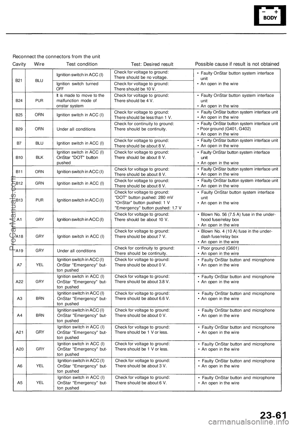
Reconnect the connectors from the unit
Cavity Wire Test condition
Test: Desired result
Possible cause if result is not obtained
B21
B24
B25
B29
B7
B10
B11
B12
B13
A1
A18
A19
A7
A22
A3
A4
A21
A20
A6
A5
BLU
PUR
ORN
ORN
BLU
BLK
ORN
GRN
PUR
GRY
GRY
GRY
YEL
GRY
BRN
BRN
GRY
GRY
YEL
YEL
Ignition switch in ACC (I)
Ignition switch turned
OFF
It is made to move to the
malfunction mode of
onstar system
Ignition switch in ACC (I)
Under all conditions
Ignition switch in ACC (I)
Ignition switch in ACC (I)
OnStar "DOT" button
pushed
Ignition switch in ACC (I)
Ignition switch in ACC (I)
Ignition switch in ACC (I)
Ignition switch in ACC (I)
Ignition switch in ACC (I)
Under all conditions
Ignition switch in ACC (I)
OnStar "Emergency" but-
ton pushed
Ignition switch in ACC (I)
OnStar "Emergency" but-
ton pushed
Ignition switch in ACC (I)
OnStar "Emergency" but-
ton pushed
Ignition switch in ACC (I)
OnStar "Emergency" but-
ton pushed
Ignition switch in ACC (I)
OnStar "Emergency" but-
ton pushed
Ignition switch in ACC (I)
OnStar "Emergency" but-
ton pushed
Ignition switch in ACC (I)
OnStar "Emergency" but-
ton pushed
Ignition switch in ACC (I)
OnStar "Emergency" but-
ton pushed
Check for voltage to ground:
There should be no voltage.
Check for voltage to ground:
There should be 10 V.
Check for voltage to ground:
There should be 4 V.
Check for voltage to ground:
There should be less than 1 V.
Check for continuity to ground:
There should be continuity.
Check for voltage to ground:
There should be about 8 V.
Check for voltage to ground:
There should be about 8 V.
Check for voltage to ground:
There should be about 8 V.
Check for voltage to ground:
There should be about 8 V.
Check for voltage to ground:
"DOT" button pushed: 280 mV
"OnStar" button pushed: 1 V
"Emergency" button pushed: 1.7 V
Check for voltage to ground:
There should be about 10 V.
Check for voltage to ground:
There should be about 7 V.
Check for continuity to ground:
There should be continuity.
Check for voltage to ground:
There should be about 0 V.
Check for voltage to ground:
There should be about 3.8 V.
Check for voltage to ground:
There should be about 6.6 V.
Check for voltage to ground:
There should be about 0 V.
Check for voltage to ground:
There should be 1 V or less.
Check for voltage to ground:
There should be 1 V or less.
Check for voltage to ground:
There should be about 3 V.
Check for voltage to ground:
There should be about 6 V.
• Faulty OnStar button system interface
unit
• An open in the wire
• Faulty OnStar button system interface
unit
• An open in the wire
• Faulty OnStar button system interface unit
• An open in the wire
• Faulty OnStar button system interface unit
• Poor ground (G401, G402)
• An open in the wire
• Faulty OnStar button system interface unit
• An open in the wire
• Faulty OnStar button system interface
unit
• An open in the wire
• Faulty OnStar button system interface unit
• An open in the wire
• Faulty OnStar button system interface unit
• An open in the wire
• Faulty OnStar button system interface
unit
• An open in the wire
• Blown No. 56 (7.5 A) fuse in the under-
hood fuse/relay box
• An open in the wire
• Blown No. 4 (10 A) fuse in the under-
dash fuse/relay box
• An open in the wire
• Poor ground (G601)
• An open in the wire
• Faulty OnStar button and microphone
• An open in the wire
• Faulty OnStar button and microphone
• An open in the wire
• Faulty OnStar button and microphone
• An open in the wire
• Faulty OnStar button and microphone
• An open in the wire
• Faulty OnStar button and microphone
• An open in the wire
• Faulty OnStar button and microphone
• An open in the wire
• Faulty OnStar button and microphone
• An open in the wire
• Faulty OnStar button and microphone
• An open in the wireProCarManuals.com
Page 55 of 1954
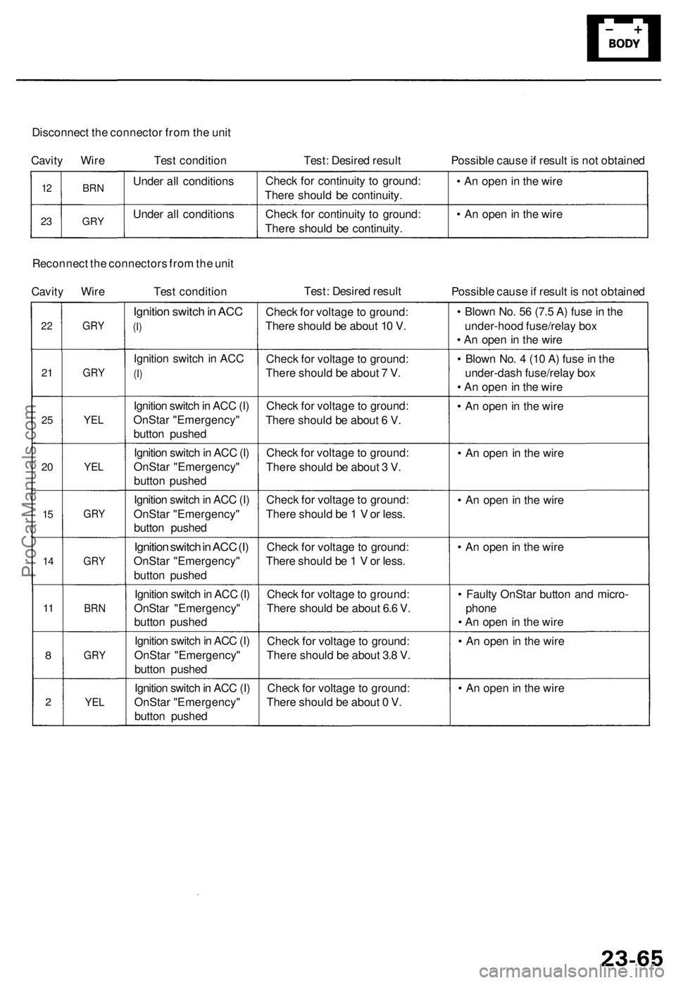
Disconnect the connector from the unit
Cavity Wire Test condition
Test: Desired result
Possible cause if result is not obtained
12
23
BRN
GRY
Under all conditions
Under all conditions
Check for continuity to ground:
There should be continuity.
Check for continuity to ground:
There should be continuity.
• An open in the wire
• An open in the wire
Reconnect the connectors from the unit
Cavity Wire Test condition
Test: Desired result
Possible cause if result is not obtained
22
21
25
20
15
14
11
8
2
GRY
GRY
YEL
YEL
GRY
GRY
BRN
GRY
YEL
Ignition switch in ACC
(I)
Ignition switch in ACC
(I)
Ignition switch in ACC (I)
OnStar "Emergency"
button pushed
Ignition switch in ACC (I)
OnStar "Emergency"
button pushed
Ignition switch in ACC (I)
OnStar "Emergency"
button pushed
Ignition switch in ACC (I)
OnStar "Emergency"
button pushed
Ignition switch in ACC (I)
OnStar "Emergency"
button pushed
Ignition switch in ACC (I)
OnStar "Emergency"
button pushed
Ignition switch in ACC (I)
OnStar "Emergency"
button pushed
Check for voltage to ground:
There should be about 10 V.
Check for voltage to ground:
There should be about 7 V.
Check for voltage to ground:
There should be about 6 V.
Check for voltage to ground:
There should be about 3 V.
Check for voltage to ground:
There should be 1 V or less.
Check for voltage to ground:
There should be 1 V or less.
Check for voltage to ground:
There should be about 6.6 V.
Check for voltage to ground:
There should be about 3.8 V.
Check for voltage to ground:
There should be about 0 V.
• Blown No. 56 (7.5 A) fuse in the
under-hood fuse/relay box
• An open in the wire
• Blown No. 4 (10 A) fuse in the
under-dash fuse/relay box
• An open in the wire
• An open in the wire
• An open in the wire
• An open in the wire
• An open in the wire
• Faulty OnStar button and micro-
phone
• An open in the wire
• An open in the wire
• An open in the wireProCarManuals.com
Page 56 of 1954
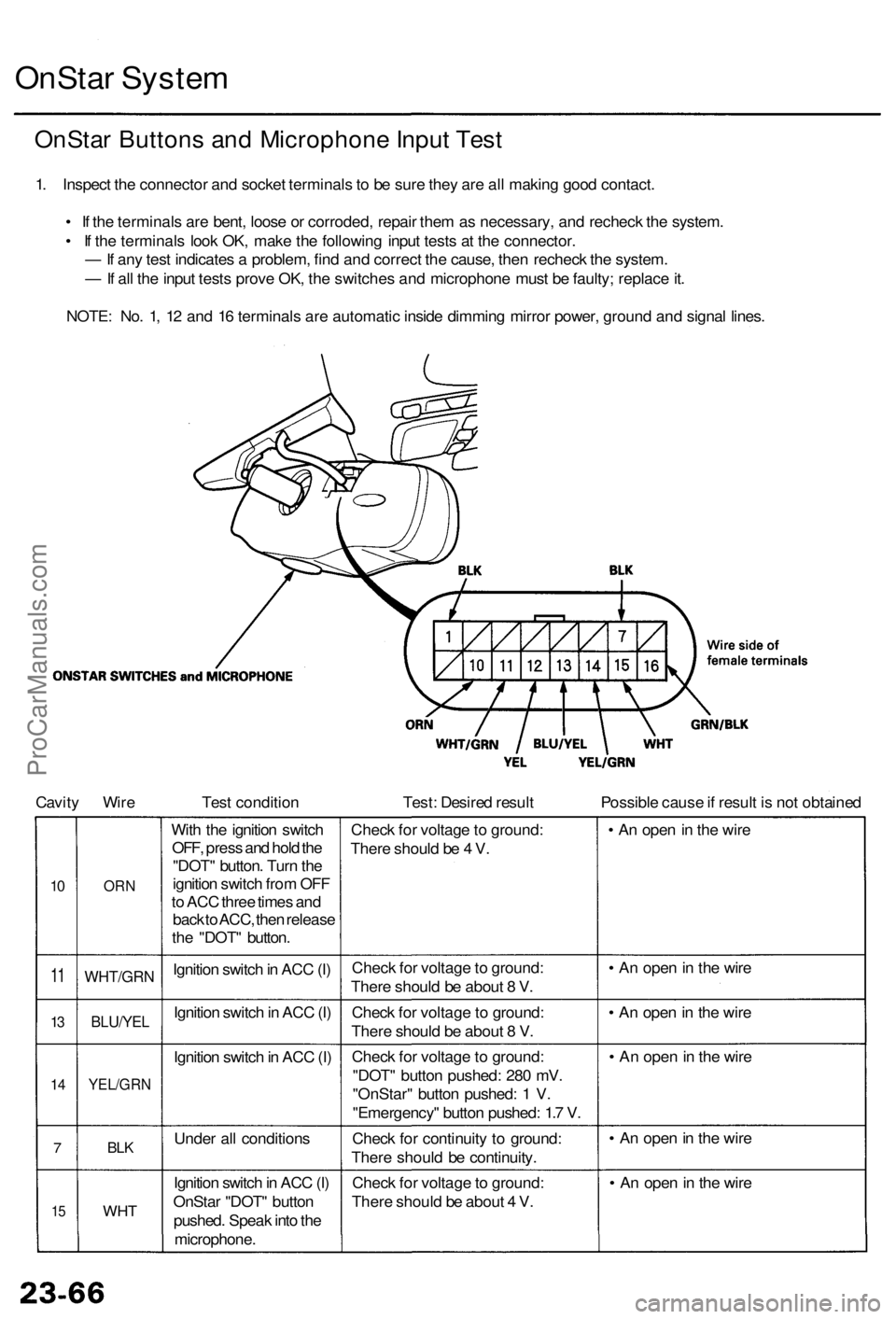
OnStar Syste m
OnSta r Button s an d Microphon e Inpu t Tes t
1. Inspec t th e connecto r an d socke t terminal s t o b e sur e the y ar e al l makin g goo d contact .
• I f th e terminal s ar e bent , loos e o r corroded , repai r the m a s necessary , an d rechec k th e system .
• I f th e terminal s loo k OK , mak e th e followin g inpu t test s a t th e connector .
— If an y tes t indicate s a problem , fin d an d correc t th e cause , the n rechec k th e system .
— If al l th e inpu t test s prov e OK , th e switche s an d microphon e mus t b e faulty ; replac e it .
NOTE : No . 1 , 1 2 an d 1 6 terminal s ar e automati c insid e dimmin g mirro r power , groun d an d signa l lines .
Cavit y Wir e Test conditio n Test: Desire d resul t Possible caus e if resul t i s no t obtaine d
10
1 1
13
1 4
7
15
OR N
WHT/GR N
BLU/YEL
YEL/GR N
BLK
WH T
With th e ignitio n switc h
OFF , pres s an d hol d th e
"DOT " button . Tur n th e
ignitio n switc h fro m OF F
t o AC C thre e time s an d
bac k to ACC , the n releas e
th e "DOT " button .
Ignitio n switc h in AC C (I )
Ignitio n switc h in AC C (I)
Ignitio n switc h in AC C (I )
Unde r al l condition s
Ignitio n switc h in AC C (I)
OnSta r "DOT " butto n
pushed . Spea k int o th e
microphone . Chec
k fo r voltag e to ground :
Ther e shoul d b e 4 V .
Chec k fo r voltag e to ground :
Ther e shoul d b e abou t 8 V .
Chec k fo r voltag e to ground :
Ther e shoul d b e abou t 8 V .
Chec k fo r voltag e to ground :
"DOT " butto n pushed : 28 0 mV .
"OnStar " butto n pushed : 1 V .
"Emergency " butto n pushed : 1. 7 V .
Chec k fo r continuit y t o ground :
Ther e shoul d b e continuity .
Chec k fo r voltag e to ground :
Ther e shoul d b e abou t 4 V . •
A n ope n in th e wir e
• A n ope n in th e wir e
• A n ope n in th e wir e
• A n ope n in th e wir e
• A n ope n in th e wir e
• A n ope n in th e wir e
ProCarManuals.com
Page 220 of 1954
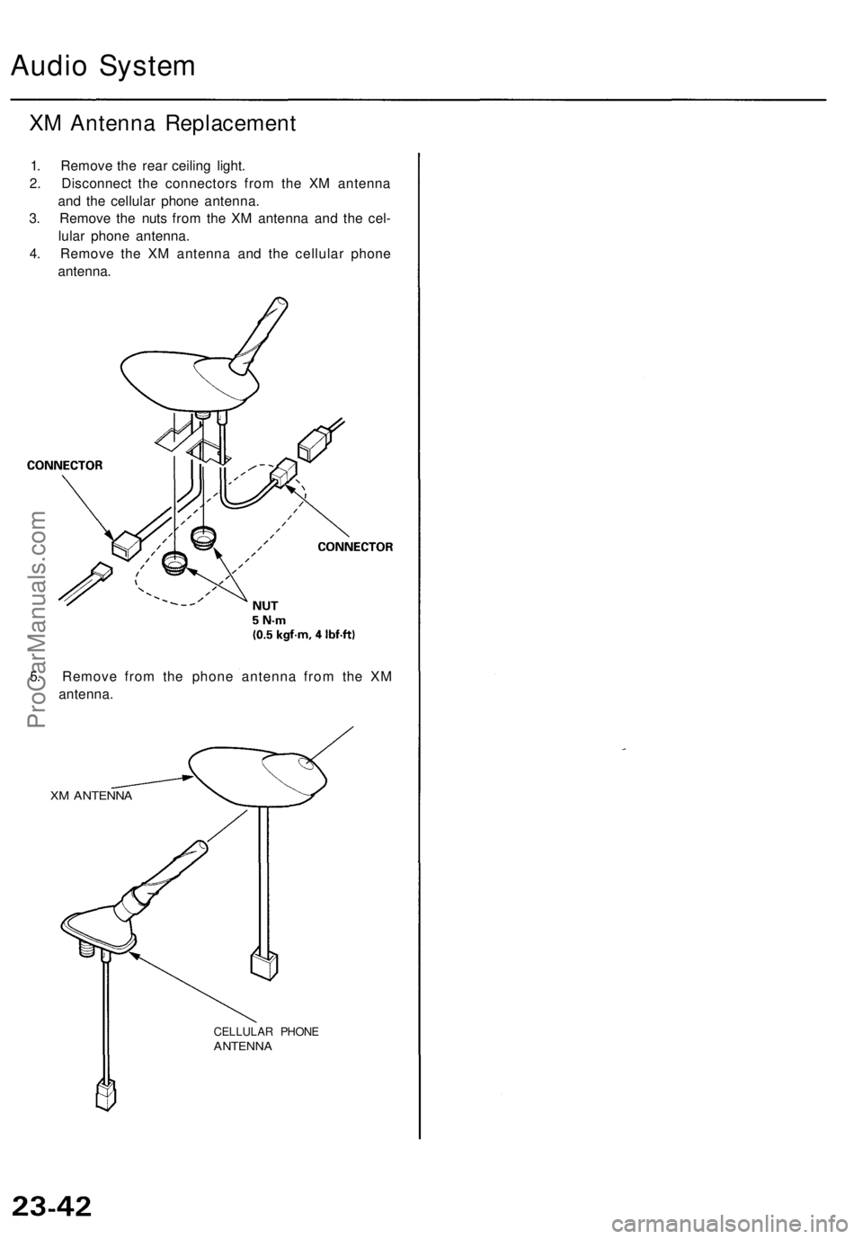
Audio System
XM Antenna Replacement
1. Remove the rear ceiling light.
2. Disconnect the connectors from the XM antenna
and the cellular phone antenna.
3. Remove the nuts from the XM antenna and the cel-
lular phone antenna.
4. Remove the XM antenna and the cellular phone
antenna.
5. Remove from the phone antenna from the XM
antenna.
XM ANTENNA
CELLULAR PHONE
ANTENNAProCarManuals.com