ACURA TL 1995 Service Repair Manual
Manufacturer: ACURA, Model Year: 1995, Model line: TL, Model: ACURA TL 1995Pages: 1771, PDF Size: 62.49 MB
Page 1061 of 1771
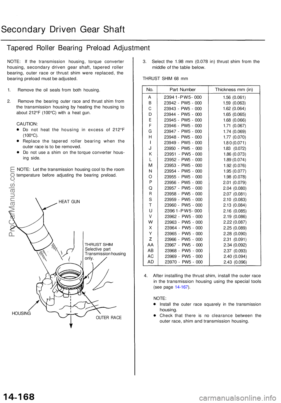
Secondary Drive n Gea r Shaf t
Tapere d Rolle r Bearin g Preloa d Adjustmen t
NOTE: I f th e transmissio n housing , torqu e converte r
housing, secondar y drive n gea r shaft , tapere d rolle r
bearing , oute r rac e o r thrus t shi m wer e replaced , th e
bearin g preloa d mus t b e adjusted .
1. Remov e th e oi l seal s fro m bot h housing .
2 . Remov e th e bearin g oute r rac e an d thrus t shi m fro m
the transmissio n housin g b y heatin g th e housin g t o
abou t 212° F (100°C ) wit h a hea t gun .
CAUTION :
Do no t hea t th e housin g i n exces s o f 212° F
(100°C) .
Replac e th e tapere d rolle r bearin g whe n th e
oute r rac e is to b e removed .
Do no t us e a shi m o n th e torqu e converte r hous -
in g side .
NOTE : Le t th e transmissio n housin g coo l t o th e roo m
temperatur e befor e adjustin g th e bearin g preload .
HEAT GU N
THRUS T SHI MSelectiv e par tTransmissio n housin g
only .
HOUSIN GOUTER RAC E
3. Selec t th e 1.9 8 m m (0.07 8 in ) thrus t shi m fro m th e
middl e o f th e tabl e below .
THRUS T SHI M 6 8 m m
No.
A
B
C
D
E
F
G
H
I
J
K
L
M
N
O
P
Q
R
S
T
U
V
W
X
Y
z
AA
A B
AC
AD
Par t Numbe r
2394 1-PW5 - 00 0
2394 2 - PW 5 - 00 0
2394 3 - PW 5 - 00 0
2394 4 - PW 5 - 00 0
2394 5 - PW 5 - 00 0
2394 6 - PW 5 - 00 0
2394 7 - PW 5 - 00 0
2394 8 - PW 5 - 00 0
2394 9 - PW 5 - 00 0
2395 0 - PW 5 - 00 0
2395 1 - PW 5 - 00 0
2395 2 - PW 5 - 00 0
2395 3 - PW 5 - 00 0
2395 4 - PW 5 - 00 0
2395 5 - PW 5 - 00 0
2395 6 - PW 5 - 00 0
2395 7 - PW 5 - 00 0
2395 8 - PW 5 - 00 0
2395 9 - PW 5 - 00 0
2396 0 - PW 5 - 00 0
239 6 1-PW5 - 00 0
2396 2 - PW 5 - 00 0
2396 3 - PW 5 - 00 0
2396 4 - PW 5 - 00 0
2396 5 - PW 5 - 00 0
2396 6 - PW 5 - 00 0
2396 7 - PW 5 - 00 0
2396 8 - PW 5 - 00 0
2396 9 - PW 5 - 00 0
2397 0 - PW 5 - 00 0
Thicknes s m m (in )
1.56 (0.061 )
1.5 9 (0.063 )
1.6 2 (0.064 )
1.65 (0.065 )
1.68 (0.066 )
1.7 1 (0.067 )
1.7 4 (0.069 )
1.7 7 (0.070 )
1. 8 0 (0.071 )
1.8 3 (0.072 )
1.8 6 (0.073 )
1.8 9 (0.074 )
1.9 2 (0.076 )
1.9 5 (0.077 )
1.9 8 (0.078 )
2.0 1 (0.079 )
2.0 4 (0.080 )
2.0 7 (0.081 )
2.1 0 (0.083 )
2.1 3 (0.084 )
2.1 6 (0.085 )
2.1 9 (0.086 )
2.2 2 (0.087 )
2.2 5 (0.089 )
2.2 8 (0.090 )
2.3 1 (0.091 )
2.34 (0.092 )
2.37 (0.093 )
2.4 0 (0.094 )
2.4 3 (0.096 )
4. Afte r installin g th e thrus t shim , instal l th e oute r rac e
in th e transmissio n housin g usin g th e specia l tool s
(see pag e 14-167 ).
NOTE :
Instal l th e oute r rac e squarel y i n th e transmissio n
housing.
Check tha t ther e i s n o clearanc e betwee n th e
oute r race , shi m an d transmissio n housing .
ProCarManuals.com
Page 1062 of 1771
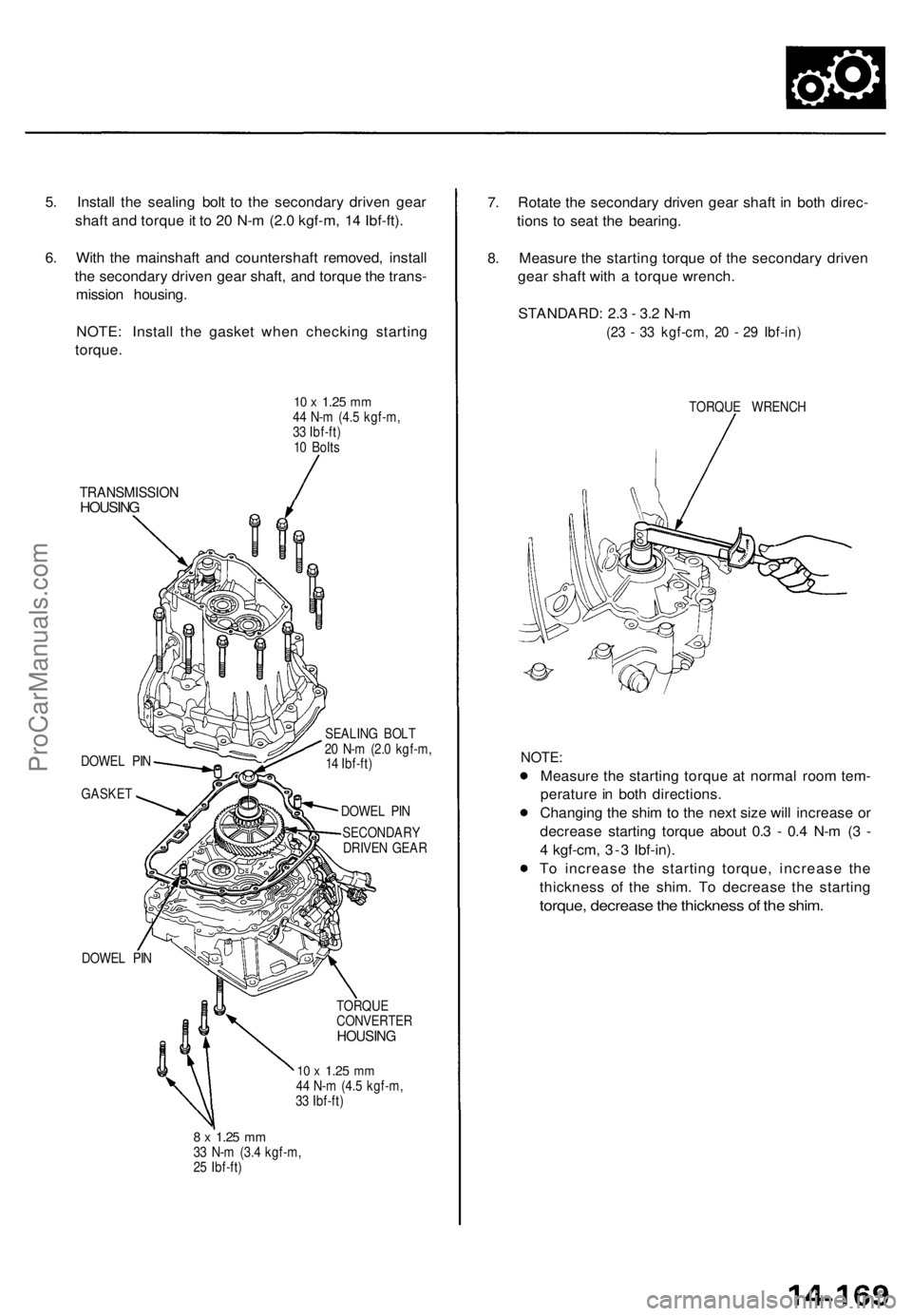
5. Install the sealing bolt to the secondary driven gear
shaft and torque it to 20 N-m (2.0 kgf-m, 14 Ibf-ft).
6. With the mainshaft and countershaft removed, install
the secondary driven gear shaft, and torque the trans-
mission housing.
NOTE: Install the gasket when checking starting
torque.
10 x
1.25
mm
44 N-m (4.5 kgf-m,
33 Ibf-ft)
10 Bolts
TRANSMISSION
HOUSING
DOWEL PIN
GASKET
DOWEL PIN
SEALING BOLT
20 N-m (2.0 kgf-m,
14 Ibf-ft)
DOWEL PIN
SECONDARY
DRIVEN GEAR
TORQUE
CONVERTER
HOUSING
10 x
1.25
mm
44 N-m (4.5 kgf-m,
33 Ibf-ft)
8 x
1.25
mm
33 N-m (3.4 kgf-m,
25 Ibf-ft)
7. Rotate the secondary driven gear shaft in both direc-
tions to seat the bearing.
8. Measure the starting torque of the secondary driven
gear shaft with a torque wrench.
STANDARD: 2.3 - 3.2 N-m
(23 - 33 kgf-cm, 20 - 29 Ibf-in)
TORQUE WRENCH
NOTE:
Measure the starting torque at normal room tem-
perature in both directions.
Changing the shim to the next size will increase or
decrease starting torque about 0.3 - 0.4 N-m (3 -
4 kgf-cm, 3-3 Ibf-in).
To increase the starting torque, increase the
thickness of the shim. To decrease the starting
torque, decrease the thickness of the shim.ProCarManuals.com
Page 1063 of 1771
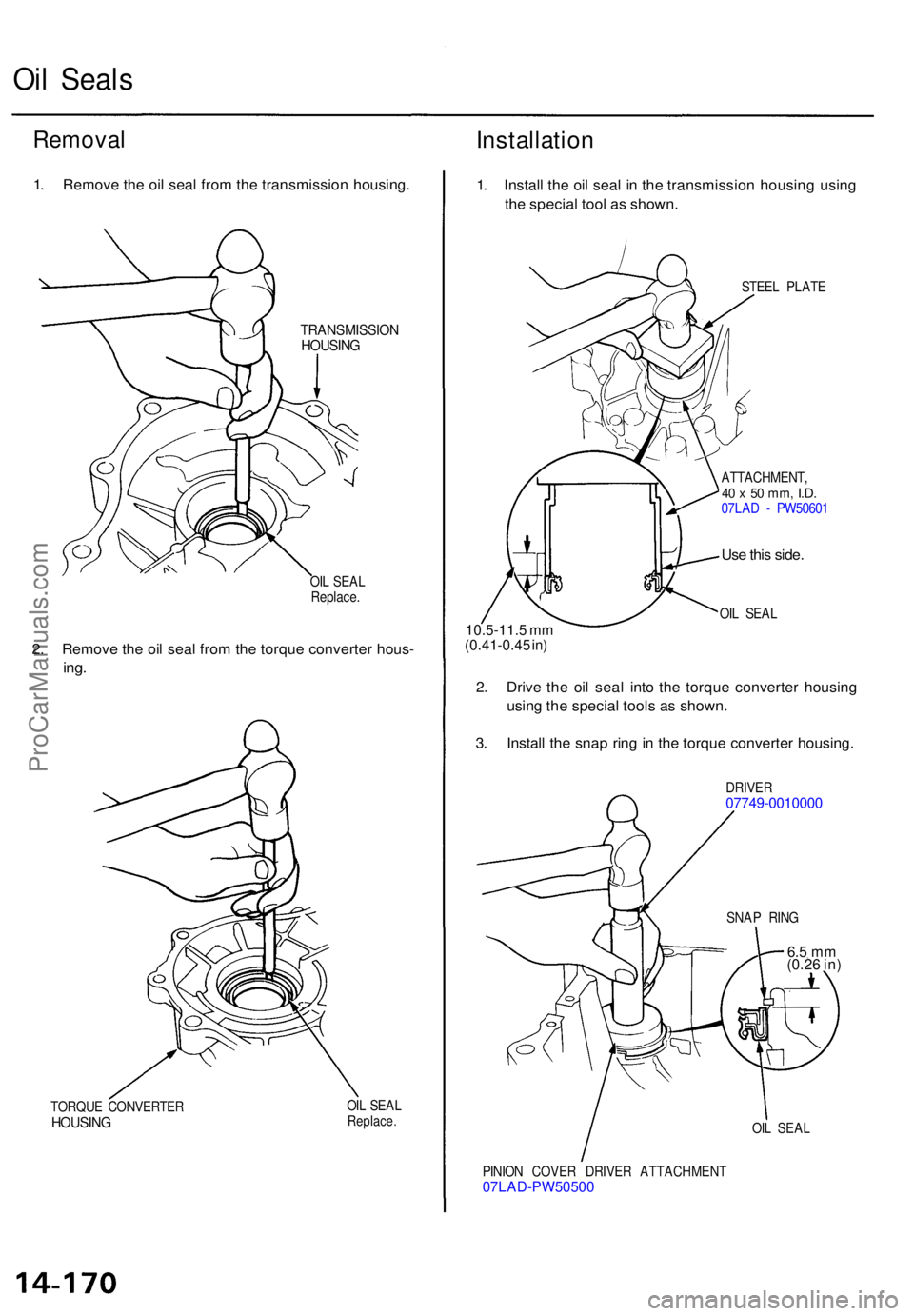
Oil Seal s
Remova lInstallatio n
1. Remov e th e oi l sea l fro m th e transmissio n housing .
TRANSMISSIO NHOUSING
OIL SEA L
Replace .
2. Remov e th e oi l sea l fro m th e torqu e converte r hous -
ing.
TORQU E CONVERTE RHOUSING
OIL SEA LReplace .
1. Instal l th e oi l sea l i n th e transmissio n housin g usin g
th e specia l too l a s shown .
STEEL PLAT E
ATTACHMENT ,
40 x 50 mm , I.D.07LA D - PW5060 1
Use thi s side .
OIL SEA L10.5-11. 5 m m
(0.41-0.4 5 in )
2. Driv e th e oi l sea l int o th e torqu e converte r housin g
usin g th e specia l tool s a s shown .
3 . Instal l th e sna p rin g in th e torqu e converte r housing .
DRIVER07749-001000 0
OIL SEA L
PINIO N COVE R DRIVE R ATTACHMEN T
07LAD-PW5050 0
SNAP RIN G
6.5 m m
(0.2 6 in )
ProCarManuals.com
Page 1064 of 1771
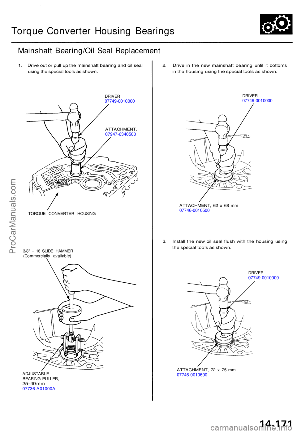
Torque Converte r Housin g Bearing s
Mainshaf t Bearing/Oi l Sea l Replacemen t
1. Driv e ou t o r pul l u p th e mainshaf t bearin g an d oi l sea l
usin g th e specia l tool s a s shown .
DRIVER07749-001000 0
ATTACHMENT ,07947-6340500
TORQUE CONVERTE R HOUSIN G
3/8 " - 1 6 SLID E HAMME R
(Commerciall y available )
ADJUSTABL E
BEARIN G PULLER ,
25 - 4 0 m m07736-A01000 A
2. Driv e i n th e ne w mainshaf t bearin g unti l i t bottom s
i n th e housin g usin g th e specia l tool s a s shown .
DRIVER07749-001000 0
ATTACHMENT , 6 2 x 68 m m07746-001050 0
3. Instal l th e ne w oi l sea l flus h wit h th e housin g usin g
th e specia l tool s a s shown .
DRIVER07749-001000 0
ATTACHMENT , 7 2 x 7 5 m m07746-001060 0
ProCarManuals.com
Page 1065 of 1771
Torque Converte r Housin g
Bearing
Transmissio n Housin g
Bearing
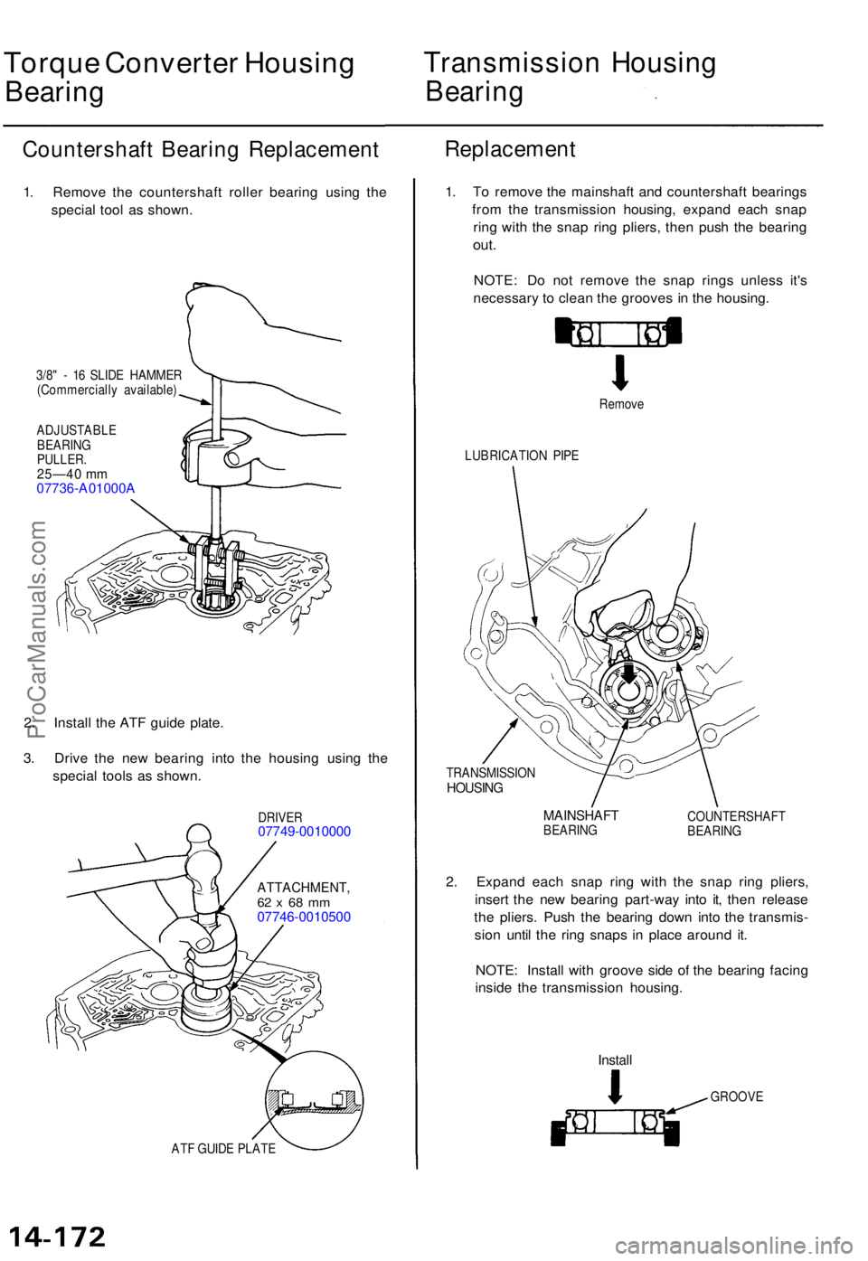
Countershaf t Bearin g Replacemen t
1. Remov e th e countershaf t rolle r bearin g usin g th e
specia l too l a s shown .
3/8" - 1 6 SLID E HAMME R
(Commerciall y available )
ADJUSTABL E
BEARIN G
PULLER .25—40 m m07736-A01000 A
2. Instal l th e AT F guid e plate .
3 . Driv e th e ne w bearin g int o th e housin g usin g th e
specia l tool s a s shown .
DRIVER07749-001000 0
ATTACHMENT ,62 x 68 m m07746-001050 0
Replacement
ATF GUID E PLAT E
1. T o remov e th e mainshaf t an d countershaf t bearing s
fro m th e transmissio n housing , expan d eac h sna p
rin g wit h th e sna p rin g pliers , the n pus h th e bearin g
out.
NOTE : D o no t remov e th e sna p ring s unles s it' s
necessar y t o clea n th e groove s i n th e housing .
Remove
LUBRICATIO N PIP E
TRANSMISSIO N
HOUSING
MAINSHAF TBEARING COUNTERSHAF
T
BEARIN G
2. Expan d eac h sna p rin g wit h th e sna p rin g pliers ,
inser t th e ne w bearin g part-wa y int o it , the n releas e
th e pliers . Pus h th e bearin g dow n int o th e transmis -
sio n unti l th e rin g snap s i n plac e aroun d it .
NOTE : Instal l wit h groov e sid e o f th e bearin g facin g
insid e th e transmissio n housing .
Install
GROOV E
ProCarManuals.com
Page 1066 of 1771
Reverse Idler Gear
Parking Brake Pawl
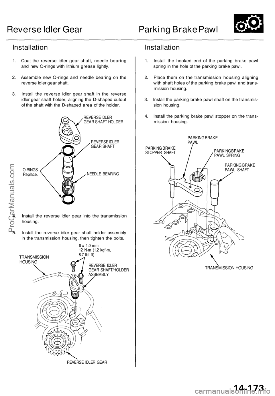
Installation
1. Coat the reverse idler gear shaft, needle bearing
and new O-rings with lithium grease lightly.
2. Assemble new O-rings and needle bearing on the
reverse idler gear shaft.
3. Install the reverse idler gear shaft in the reverse
idler gear shaft holder, aligning the D-shaped cutout
of the shaft with the D-shaped area of the holder.
REVERSE IDLER
GEAR SHAFT HOLDER
REVERSE IDLER
GEAR SHAFT
O-RINGS
Replace.
NEEDLE BEARING
4. Install the reverse idler gear into the transmission
housing.
5. Install the reverse idler gear shaft holder assembly
in the transmission housing, then tighten the bolts.
TRANSMISSION
HOUSING
6 x 1.0 mm
12 N-m (1.2 kgf-m,
8.7 Ibf-ft)
REVERSE IDLER
GEAR SHAFT/HOLDER
ASSEMBLY
REVERSE IDLER GEAR
Installation
1. Install the hooked end of the parking brake pawl
spring in the hole of the parking brake pawl.
2. Place them on the transmission housing aligning
with shaft holes of the parking brake pawl and trans-
mission housing.
3. Install the parking brake pawl shaft on the transmis-
sion housing.
4. Install the parking brake pawl stopper on the trans-
mission housing.
PARKING BRAKE
PAWL
PARKING BRAKE
STOPPER SHAFT
PARKING BRAKE
PAWL SPRING
PARKING BRAKE
PAWL SHAFT
TRANSMISSION HOUSINGProCarManuals.com
Page 1067 of 1771
Parking Brake Roller Rod
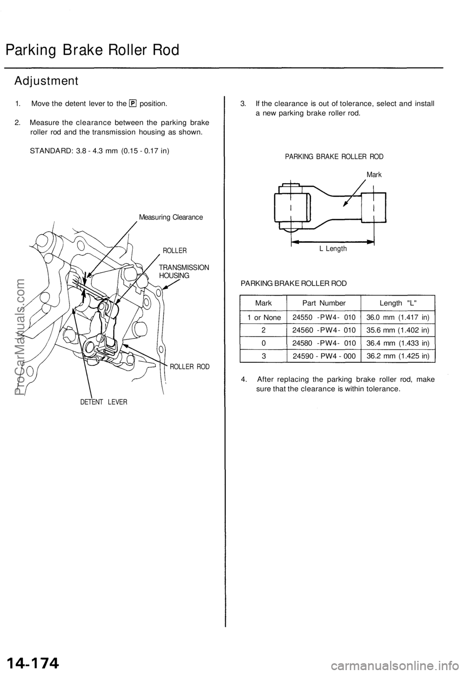
Adjustment
1. Move the detent lever to the position.
2. Measure the clearance between the parking brake
roller rod and the transmission housing as shown.
STANDARD: 3.8 - 4.3 mm (0.15 - 0.17 in)
Measuring Clearance
ROLLER
TRANSMISSION
HOUSING
DETENT LEVER
ROLLER ROD
3. If the clearance is out of tolerance, select and install
a new parking brake roller rod.
PARKING BRAKE ROLLER ROD
Mark
L Length
PARKING BRAKE ROLLER ROD
Mark
1 or None
2
0
3
Part Number
24550 -PW4- 010
24560 -PW4- 010
24580 -PW4- 010
24590 - PW4 - 000
Length "L"
36.0 mm (1.417 in)
35.6 mm (1.402 in)
36.4 mm (1.433 in)
36.2 mm (1.425 in)
4. After replacing the parking brake roller rod, make
sure that the clearance is within tolerance.ProCarManuals.com
Page 1068 of 1771
Control Shaft/Detent Spring
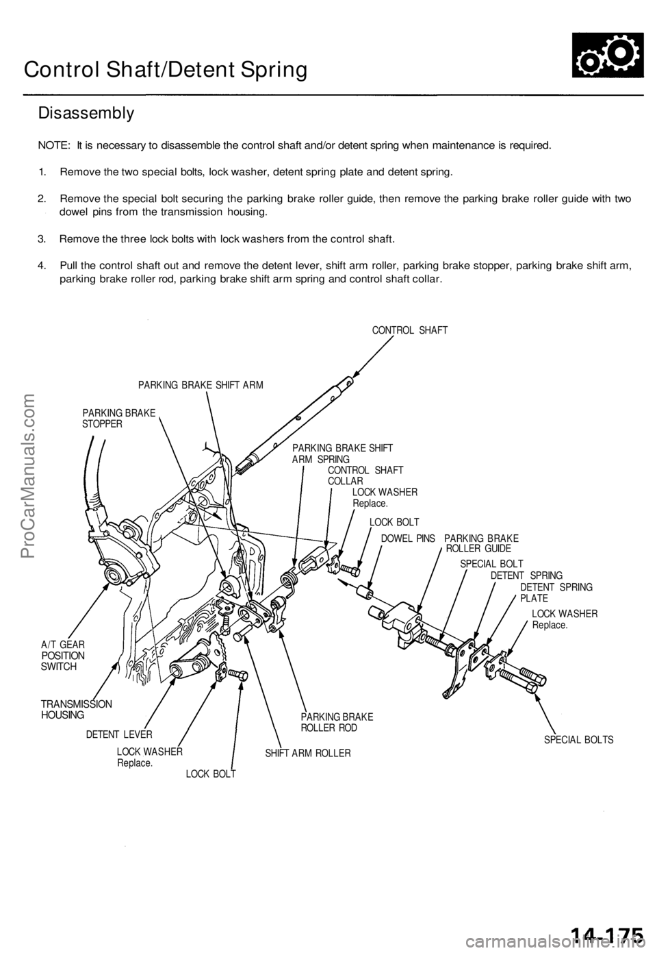
Disassembly
NOTE: It is necessary to disassemble the control shaft and/or detent spring when maintenance is required.
1. Remove the two special bolts, lock washer, detent spring plate and detent spring.
2. Remove the special bolt securing the parking brake roller guide, then remove the parking brake roller guide with two
dowel pins from the transmission housing.
3. Remove the three lock bolts with lock washers from the control shaft.
4. Pull the control shaft out and remove the detent lever, shift arm roller, parking brake stopper, parking brake shift arm,
parking brake roller rod, parking brake shift arm spring and control shaft collar.
CONTROL SHAFT
PARKING BRAKE SHIFT ARM
PARKING BRAKE
STOPPER
DOWEL PINS PARKING BRAKE
ROLLER GUIDE
A/T GEAR
POSITION
SWITCH
TRANSMISSION
HOUSING
DETENT LEVER
LOCK WASHER
Replace.
SHIFT ARM ROLLER
SPECIAL BOLT
DETENT SPRING
DETENT SPRING
PLATE
LOCK WASHER
Replace.
SPECIAL BOLTS
LOCK BOLT
PARKING BRAKE
ROLLER ROD
LOCK BOLT
LOCK WASHER
Replace.
CONTROL SHAFT
COLLAR
PARKING BRAKE SHIFT
ARM SPRINGProCarManuals.com
Page 1069 of 1771
Control Shaft/Deten t Sprin g
Reassembl y
NOTE:
Coat al l part s wit h ATF .
Replac e th e loc k washers .
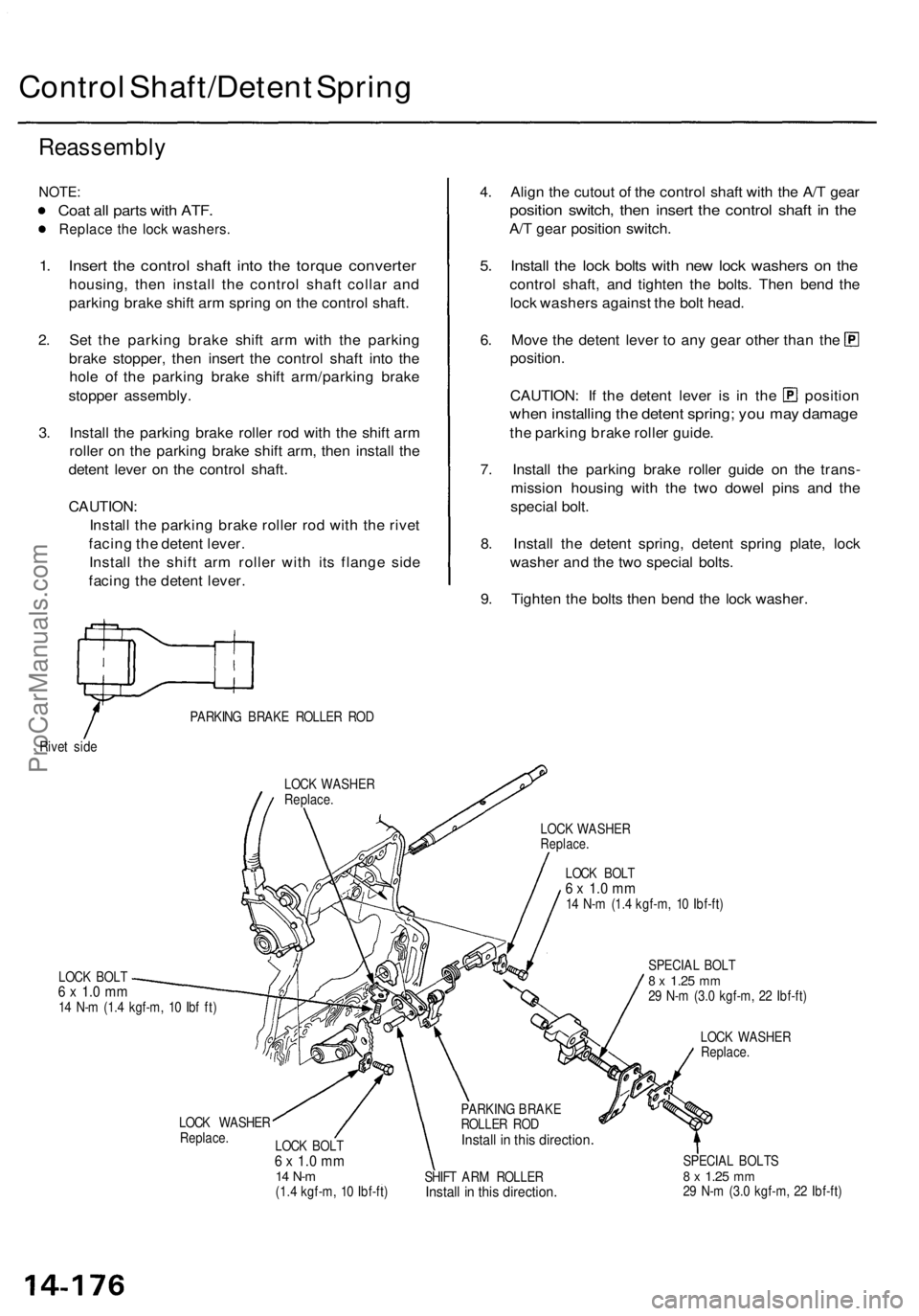
1. Inser t th e contro l shaf t int o th e torqu e converte r
housing, the n instal l th e contro l shaf t colla r an d
parkin g brak e shif t ar m sprin g o n th e contro l shaft .
2 . Se t th e parkin g brak e shif t ar m wit h th e parkin g
brak e stopper , the n inser t th e contro l shaf t int o th e
hol e o f th e parkin g brak e shif t arm/parkin g brak e
stoppe r assembly .
3 . Instal l th e parkin g brak e rolle r ro d wit h th e shif t ar m
rolle r o n th e parkin g brak e shif t arm , the n instal l th e
deten t leve r o n th e contro l shaft .
CAUTION :
Instal l th e parkin g brak e rolle r ro d wit h th e rive t
facin g th e deten t lever .
Instal l th e shif t ar m rolle r wit h it s flang e sid e
facin g th e deten t lever .
Rivet sid e PARKIN
G BRAK E ROLLE R RO D
LOC K WASHE R
Replace.
LOCK BOL T6 x 1. 0 m m14 N- m (1. 4 kgf-m , 1 0 Ib f ft )
4. Alig n th e cutou t o f th e contro l shaf t wit h th e A/ T gea r
positio n switch , the n inser t th e contro l shaf t i n th e
A/T gea r positio n switch .
5. Instal l th e loc k bolt s wit h ne w loc k washer s o n th e
contro l shaft , an d tighte n th e bolts . The n ben d th e
loc k washer s agains t th e bol t head .
6. Mov e th e deten t leve r t o an y gea r othe r tha n th e
position .
CAUTION : I f th e deten t leve r i s i n th e positio n
when installin g th e deten t spring ; yo u ma y damag e
the parkin g brak e rolle r guide .
7 . Instal l th e parkin g brak e rolle r guid e o n th e trans -
missio n housin g wit h th e tw o dowe l pin s an d th e
specia l bolt .
8 . Instal l th e deten t spring , deten t sprin g plate , loc k
washe r an d th e tw o specia l bolts .
9 . Tighte n th e bolt s the n ben d th e loc k washer .
LOCK WASHE RReplace.
LOCK BOL T6 x 1. 0 m m14 N- m (1. 4 kgf-m , 1 0 Ibf-ft )
LOC K WASHE R
Replace.LOCK BOL T6 x 1. 0 m m14 N- m(1.4 kgf-m , 1 0 Ibf-ft ) SPECIA
L BOL T
8 x 1.2 5 mm29 N- m (3. 0 kgf-m , 2 2 Ibf-ft )
LOC K WASHE R
Replace.
PARKING BRAK E
ROLLE R RO D
Instal l i n thi s directio n
SHIFT AR M ROLLE RInstall i n thi s direction .
SPECIAL BOLT S8 x 1.2 5 mm29 N- m (3. 0 kgf-m , 2 2 Ibf-ft )
ProCarManuals.com
Page 1070 of 1771
Transmission
Reassembly
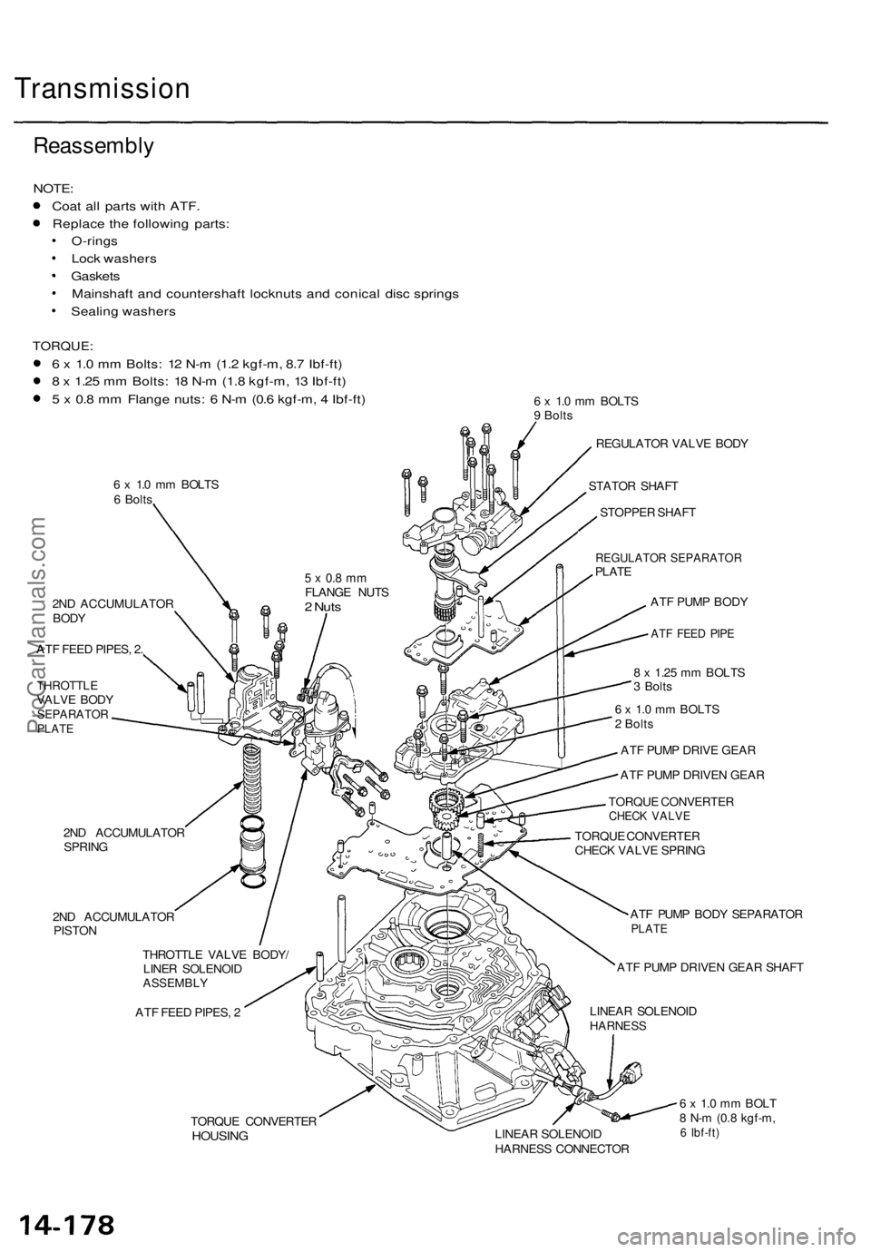
NOTE:
Coat all parts with ATF.
Replace the following parts:
O-rings
Lock washers
Gaskets
Mainshaft and countershaft locknuts and conical disc springs
Sealing washers
TORQUE:
6 x 1.0 mm Bolts: 12 N-m (1.2 kgf-m, 8.7 Ibf-ft)
8 x 1.25 mm Bolts: 18 N-m (1.8 kgf-m, 13 Ibf-ft)
5 x 0.8 mm Flange nuts: 6 N-m (0.6 kgf-m, 4 Ibf-ft)
6 x 1.0 mm BOLTS
6 Bolts
6 x 1.0 mm BOLTS
9 Bolts
2ND ACCUMULATOR
BODY
ATF FEED PIPES, 2.
THROTTLE
VALVE BODY
SEPARATOR
PLATE
2ND ACCUMULATOR
SPRING
2ND ACCUMULATOR
PISTON
THROTTLE VALVE BODY/
LINER SOLENOID
ASSEMBLY
ATF FEED PIPES, 2
REGULATOR VALVE BODY
STATOR SHAFT
STOPPER SHAFT
REGULATOR SEPARATOR
PLATE
ATF PUMP BODY
ATF FEED PIPE
8 x 1.25 mm BOLTS
3 Bolts
6 x 1.0 mm BOLTS
2 Bolts
ATF PUMP DRIVE GEAR
ATF PUMP DRIVEN GEAR
TORQUE CONVERTER
CHECK VALVE
TORQUE CONVERTER
CHECK VALVE SPRING
ATF PUMP BODY SEPARATOR
PLATE
ATF PUMP DRIVEN GEAR SHAFT
LINEAR SOLENOID
HARNESS
TORQUE CONVERTER
HOUSING
LINEAR SOLENOID
HARNESS CONNECTOR
6 x 1.0 mm BOLT
8 N-m (0.8 kgf-m,
6 Ibf-ft)
5 x 0.8 mm
FLANGE NUTS
2 NutsProCarManuals.com