roof ACURA TL 1995 Service Repair Manual
[x] Cancel search | Manufacturer: ACURA, Model Year: 1995, Model line: TL, Model: ACURA TL 1995Pages: 1771, PDF Size: 62.49 MB
Page 899 of 1771
Fuel Tube/Quick-Connec t Fitting s
Precaution s
Do no t smok e whil e workin g o n th e fue l
system . Kee p ope n flame s awa y fro m you r wor k area .
Th e fue l tube/quick-connec t fitting s assembl y connect s
th e in-tan k fue l pum p wit h th e fue l fee d pipe . Fo r remov -
in g o r installin g th e fue l pum p an d fue l tank , i t i s neces -
sar y t o disconnec t o r connec t th e quick-connec t fittings .
Pay attentio n to following :
The fue l tube/quick-connec t fitting s assembl y i s no t
heat-resistant ; b e carefu l no t t o damag e it durin g weld -
in g o r othe r heat-generatin g procedures .
Th e fue l tube/quick-connec t fitting s assembl y i s no t
acid-proof ; d o no t touc h i t wit h a sho p towe l whic h
wa s use d fo r wipin g batter y electrolyte . Replac e th e
fue l tube/quick-connec t fitting s assembl y i f i t cam e
int o contac t wit h electrolyt e o r somethin g similar .
Whe n connectin g o r disconnectin g th e fue l tube/quick -
connec t fitting s assembly , b e carefu l no t t o ben d o r
twis t i t excessively . Replac e i t i f damaged .
A disconnecte d quick-connec t fittin g ca n b e reconnected ,
bu t th e retaine r o n th e matin g pip e canno t b e reuse d onc e
i t ha s bee n remove d fro m th e pipe . Replac e th e retaine r
whe n
— Replacin g th e fue l pump .
— Replacin g th e fue l fee d pipe .
— It ha s bee n remove d fro m th e pipe .
— It i s damaged .
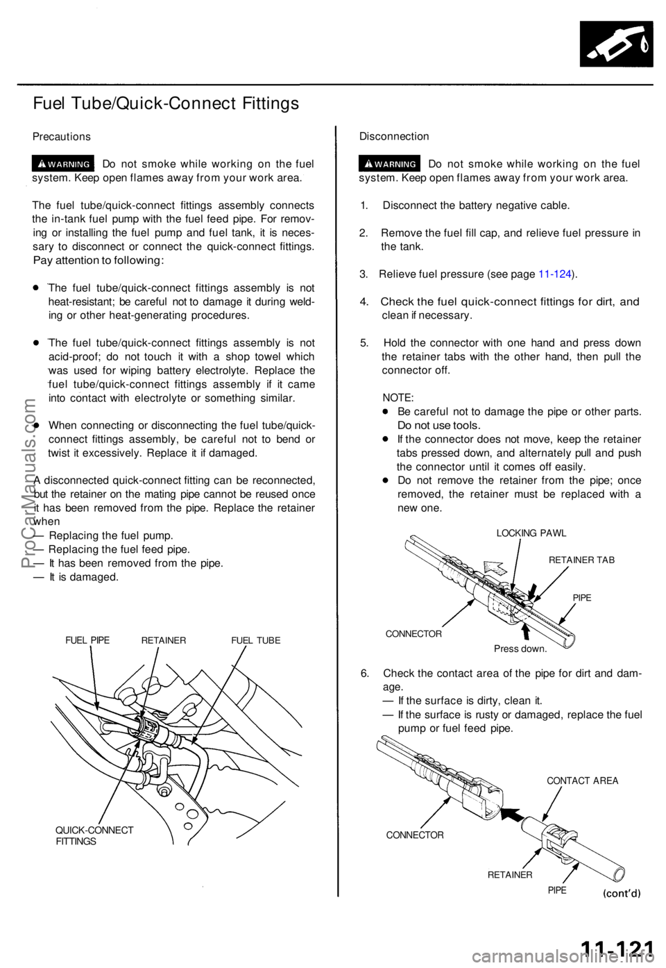
FUEL PIP ERETAINE RFUEL TUB E
QUICK-CONNEC TFITTINGS
Disconnectio n
Do no t smok e whil e workin g o n th e fue l
system . Kee p ope n flame s awa y fro m you r wor k area .
1 . Disconnec t th e batter y negativ e cable .
2 . Remov e th e fue l fil l cap , an d reliev e fue l pressur e in
th e tank .
3 . Reliev e fue l pressur e (se e pag e 11-124 ).
4 . Chec k th e fue l quick-connec t fitting s fo r dirt , an d
clea n if necessary .
5 . Hol d th e connecto r wit h on e han d an d pres s dow n
th e retaine r tab s wit h th e othe r hand , the n pul l th e
connecto r off .
NOTE :
Be carefu l no t t o damag e th e pip e o r othe r parts .
Do no t us e tools .
If th e connecto r doe s no t move , kee p th e retaine r
tab s presse d down , an d alternatel y pul l an d pus h
th e connecto r unti l i t come s of f easily .
D o no t remov e th e retaine r fro m th e pipe ; onc e
removed , th e retaine r mus t b e replace d wit h a
ne w one .
LOCKIN G PAW L
RETAINE R TA B
PIPE
CONNECTO R
Press down .
6. Chec k th e contac t are a o f th e pip e fo r dir t an d dam -
age.
— If th e surfac e is dirty , clea n it .
— If th e surface is rust y o r damaged , replac e th e fue l
pum p o r fue l fee d pipe .
CONTAC T ARE A
CONNECTO R
RETAINER
PIPE
ProCarManuals.com
Page 1296 of 1771
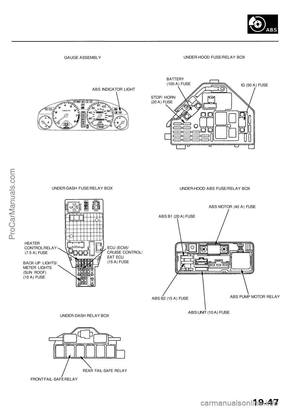
GAUGE ASSEMBLY
UNDER-HOOD FUSE/RELAY BOX
ABS INDICATOR LIGHT
BATTERY
(100 A) FUSE
IG (50 A) FUSE
STOP/ HORN
(20 A) FUSE
UNDER-DASH FUSE/RELAY BOX
UNDER-HOOD ABS FUSE/RELAY BOX
HEATER
CONTROL RELAY
(7.5 A) FUSE
BACK-UP LIGHTS/
METER LIGHTS
(SUN ROOF)
(10 A) FUSE
ECU (ECM)/
CRUISE CONTROL/
EAT ECU
(15 A) FUSE
ABS MOTOR (40 A) FUSE
ABS B1 (20 A) FUSE
ABS B2 (15 A) FUSE
ABS PUMP MOTOR RELAY
UNDER-DASH RELAY BOX
ABS UNIT (10 A) FUSE
REAR FAIL-SAFE RELAY
FRONT FAIL-SAFE RELAYProCarManuals.com
Page 1322 of 1771
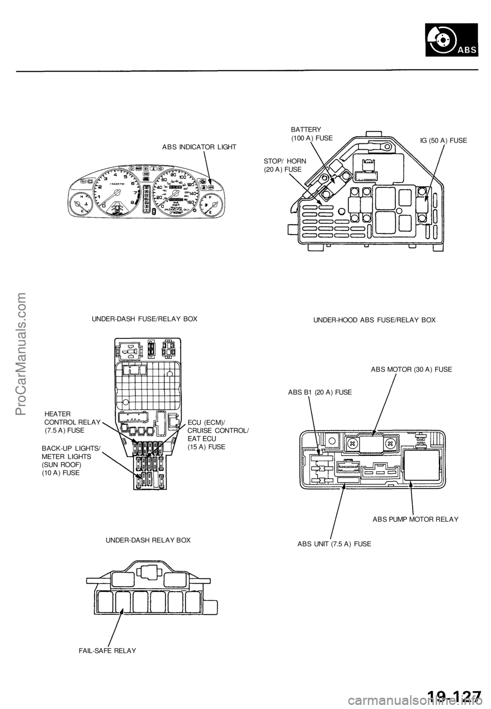
ABS INDICATOR LIGHT
BATTERY
(100 A) FUSE
STOP/ HORN
(20 A) FUSE
IG (50 A) FUSE
UNDER-DASH FUSE/RELAY BOX
UNDER-HOOD ABS FUSE/RELAY BOX
HEATER
CONTROL RELAY
(7.5 A) FUSE
BACK-UP LIGHTS/
METER LIGHTS
(SUN ROOF)
(10 A) FUSE
ECU (ECM)/
CRUISE CONTROL/
EAT ECU
(15 A) FUSE
ABS MOTOR (30 A) FUSE
ABS B1 (20 A) FUSE
UNDER-DASH RELAY BOX
ABS PUMP MOTOR RELAY
ABS UNIT (7.5 A) FUSE
FAIL-SAFE RELAYProCarManuals.com
Page 1395 of 1771
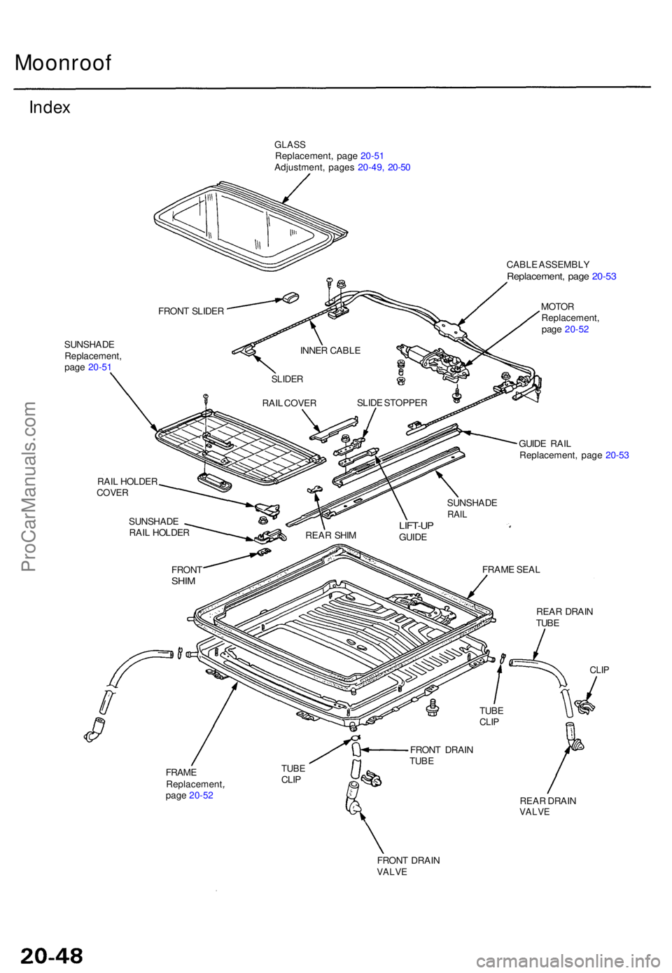
Moonroof
Index
GLAS SReplacement , pag e 20-5 1
Adjustment , page s 20-49 , 20-5 0
CABLE ASSEMBL Y
Replacement , pag e 20-5 3
MOTO R
Replacement ,
pag e 20-5 2
SUNSHAD E
Replacement ,
pag e 20-5 1
FRAME
Replacement ,
pag e 20-5 2 GUID
E RAI L
Replacement , pag e 20-5 3
CLIP
REA R DRAI NVALV E
FRON T DRAI NVALVE
TUBECLIP FRON
T DRAI N
TUB E TUB
E
CLIP
REA R DRAI N
TUB E
FRAM
E SEA L
LIFT-U PGUIDE
REA
R SHI M
FRON T
SHIM
SUNSHAD E
RAI L HOLDE R
RAI
L HOLDE R
COVERSUNSHAD ERAIL
SLID E STOPPE R
INNE
R CABL E
SLIDER
RAIL COVE R
FRON
T SLIDE R
ProCarManuals.com
Page 1397 of 1771
Moonroof
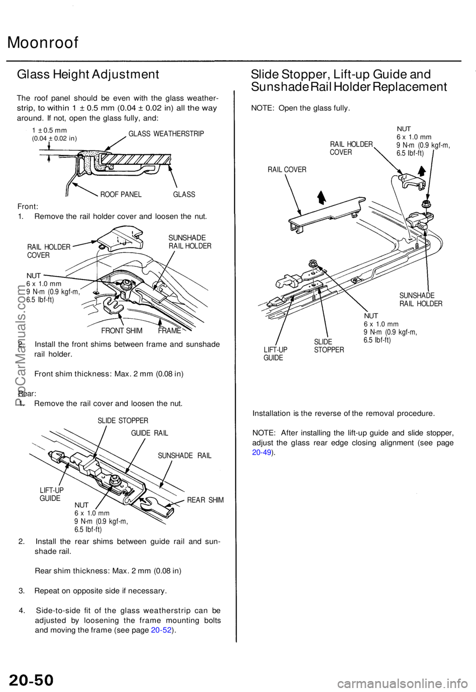
Glass Heigh t Adjustmen t
The roo f pane l shoul d b e eve n wit h th e glas s weather -
strip, t o withi n 1 ± 0.5 m m (0.0 4 ± 0.0 2 in ) al l th e wa y
around . I f not , ope n th e glas s fully , and :
1 ± 0. 5 m m(0.0 4 ± 0.02 in)GLAS S WEATHERSTRI P
ROO F PANE L GLAS S
Front:
1. Remov e th e rai l holde r cove r an d loose n th e nut .
SUNSHAD ERAIL HOLDE R
RAI L HOLDE R
COVE R
NUT6 x 1. 0 m m9 N- m (0. 9 kgf-m ,
6. 5 Ibf-ft )
FRON T SHI M FRAM E
2. Instal l th e fron t shim s betwee n fram e an d sunshad e
rai l holder .
Fron t shi m thickness : Max . 2 m m (0.0 8 in )
Rear :
1. Remov e th e rai l cove r an d loose n th e nut .
SLID E STOPPE R
GUID E RAI L
SUNSHAD E RAI L
REA R SHI M
LIFT-U
P
GUIDENUT6 x 1. 0 m m9 N- m (0. 9 kgf-m ,
6. 5 Ibf-ft )
2. Instal l th e rea r shim s betwee n guid e rai l an d sun -
shad e rail .
Rea r shi m thickness : Max . 2 m m (0.0 8 in )
3 . Repea t o n opposit e sid e if necessary .
4 . Side-to-sid e fi t o f th e glas s weatherstri p ca n b e
adjuste d b y loosenin g th e fram e mountin g bolt s
an d movin g th e fram e (se e pag e 20-52 ).
Slid e Stopper , Lift-u p Guid e an d
Sunshad e Rai l Holde r Replacemen t
NOTE: Ope n th e glas s fully .
RAIL HOLDE RCOVER
NUT6 x 1. 0 m m9 N- m (0. 9 kgf-m ,
6. 5 Ibf-ft )
RAI L COVE R
SUNSHADE
RAI L HOLDE R
LIFT-U P
GUID E SLID
E
STOPPE R
NUT6 x 1. 0 m m9 N- m (0. 9 kgf-m ,
6. 5 Ibf-ft )
Installatio n i s th e revers e o f th e remova l procedure .
NOTE : Afte r installin g th e lift-u p guid e an d slid e stopper ,
adjus t th e glas s rea r edg e closin g alignmen t (se e pag e
20-49 ).
ProCarManuals.com
Page 1399 of 1771
Moonroof
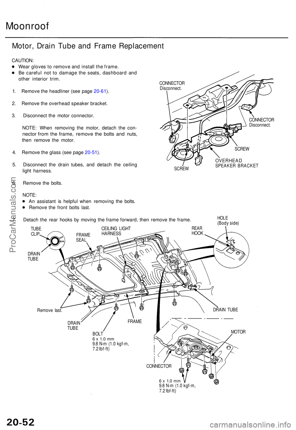
Motor, Drai n Tub e an d Fram e Replacemen t
CAUTION:
Wea r glove s t o remov e an d instal l th e frame .
B e carefu l no t t o damag e th e seats , dashboar d an d
othe r interio r trim .
1 . Remov e th e headline r (se e pag e 20-61 ).
2 . Remov e th e overhea d speake r bracket .
3 . Disconnec t th e moto r connector .
NOTE : Whe n removin g th e motor , detac h th e con -
necto r fro m th e frame , remov e th e bolt s an d nuts ,
then remov e th e motor .
4 . Remov e th e glas s (se e pag e 20-51 ).
5 . Disconnec t th e drai n tubes , an d detac h th e ceilin g
ligh t harness .
6 . Remov e th e bolts .
CONNECTO R
Disconnect .
SCREW
CONNECTO R
Disconnect .
SCREW
OVERHEA DSPEAKER BRACKE T
NOTE:
A n assistan t i s helpfu l whe n removin g th e bolts .
Remov e th e fron t bolt s last .
7 . Detac h th e rea r hook s b y movin g th e fram e forward , the n remov e th e frame .
DRAIN
TUB E
HOL E(Bod y side )
Remov e last .
DRAI N
TUB E
BOL T6 x 1. 0 m m9.8 N- m (1. 0 kgf-m ,
7. 2 Ibf-ft )
6 x 1. 0 m m9.8 N- m (1. 0 kgf-m ,
7. 2 Ibf-ft ) MOTO
R
CONNECTO R
FRAM
E DRAI
N TUB E
REARHOO K
CEILIN
G LIGH THARNES SFRAMESEAL
TUBECLIP
ProCarManuals.com
Page 1402 of 1771
Moonroof
Guide Rails/Cabl e Assembl y
Replacemen t (cont'd )
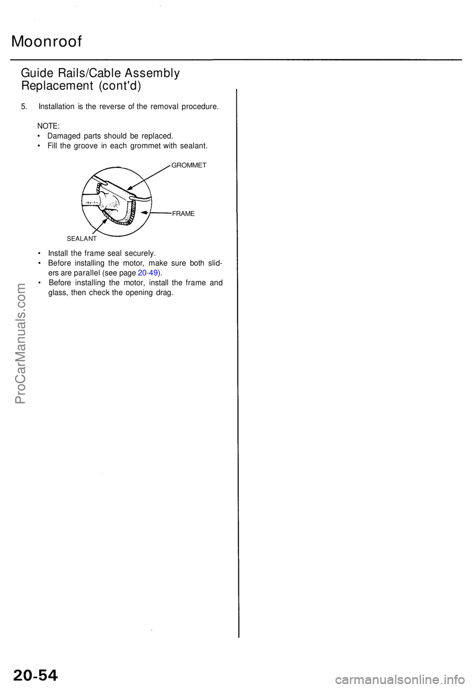
5. Installatio n i s th e revers e o f th e remova l procedure .
NOTE:
• Damage d part s shoul d b e replaced .
• Fil l th e groov e i n eac h gromme t wit h sealant .
GROMME T
FRAME
SEALAN T
• Instal l th e fram e sea l securely .
• Befor e installin g th e motor , mak e sur e bot h slid -
er s ar e paralle l (se e pag e 20-49 ).
• Befor e installin g th e motor , instal l th e fram e an d
glass , the n chec k th e openin g drag .
ProCarManuals.com
Page 1403 of 1771
Moonroof
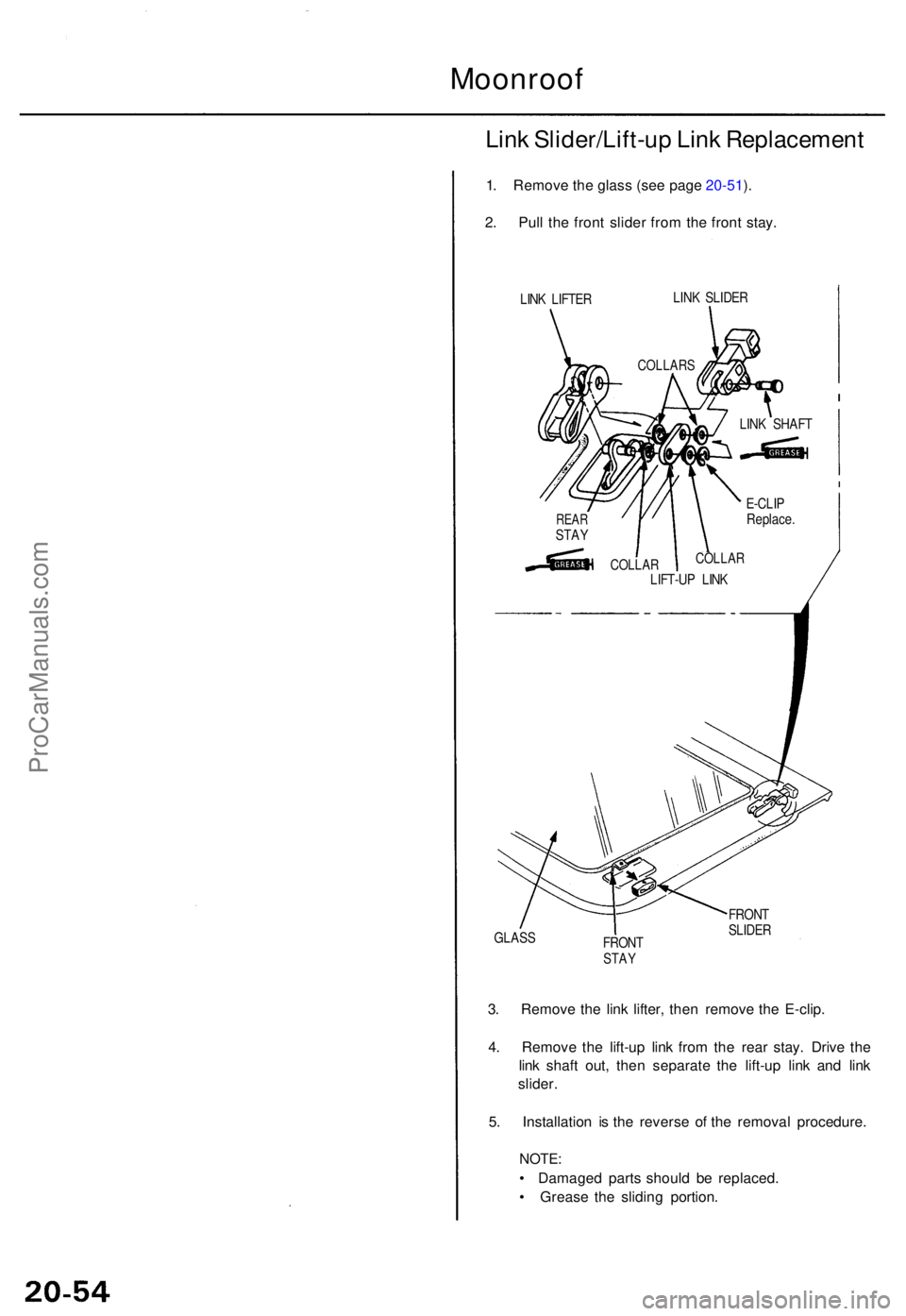
Link Slider/Lift-u p Lin k Replacemen t
1. Remov e th e glas s (se e pag e 20-51 ).
2 . Pul l th e fron t slide r fro m th e fron t stay .
LINK LIFTE R LIN
K SLIDE R
GLAS S
FRONT
STAY
FRON T
SLIDE R
3. Remov e th e lin k lifter , the n remov e th e E-clip .
4 . Remov e th e lift-u p lin k fro m th e rea r stay . Driv e th e
lin k shaf t out , the n separat e th e lift-u p lin k an d lin k
slider .
5 . Installatio n i s th e revers e o f th e remova l procedure .
NOTE:
• Damage d part s shoul d b e replaced .
• Greas e th e slidin g portion .
COLLAR S
LINK SHAF T
E-CLI P
Replace .
COLLAR
LIFT-UP LIN KCOLLA R
REARSTAY
ProCarManuals.com
Page 1457 of 1771
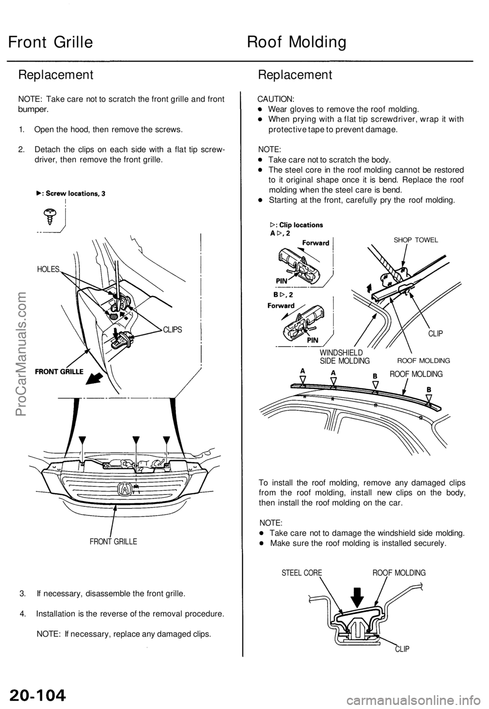
Front Grille
Roof Molding
Replacement
NOTE: Take care not to scratch the front grille and front
bumper.
1. Open the hood, then remove the screws.
2. Detach the clips on each side with a flat tip screw-
driver, then remove the front grille.
Replacement
FRONT GRILLE
3. If necessary, disassemble the front grille.
4. Installation is the reverse of the removal procedure.
NOTE: If necessary, replace any damaged clips.
CAUTION:
Wear gloves to remove the roof molding.
When prying with a flat tip screwdriver, wrap it with
protective tape to prevent damage.
NOTE:
Take care not to scratch the body.
The steel core in the roof molding cannot be restored
to it original shape once it is bend. Replace the roof
molding when the steel care is bend.
Starting at the front, carefully pry the roof molding.
SHOP TOWEL
WINDSHIELD
SIDE MOLDING
CLIP
ROOF MOLDING
ROOF MOLDING
To install the roof molding, remove any damaged clips
from the roof molding, install new clips on the body,
then install the roof molding on the car.
NOTE:
Take care not to damage the windshield side molding.
Make sure the roof molding is installed securely.
STEEL CORE
ROOF MOLDING
CLIP
CLIPS
HOLES.ProCarManuals.com
Page 1480 of 1771
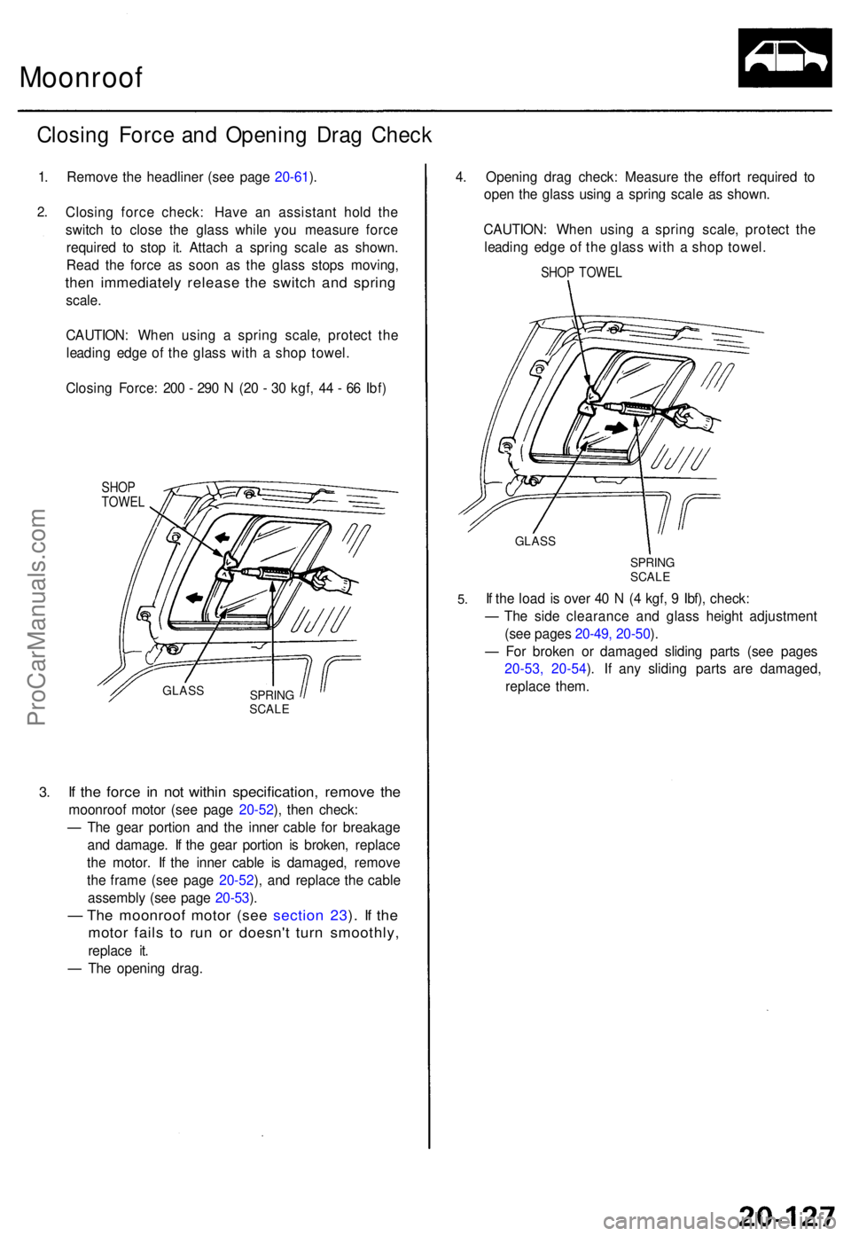
Moonroof
Closing Forc e an d Openin g Dra g Chec k
1. Remov e th e headline r (se e pag e 20-61 ).
2 .
3.
Closin g forc e check : Hav e a n assistan t hol d th e
switc h t o clos e th e glas s whil e yo u measur e forc e
require d t o sto p it . Attac h a sprin g scal e a s shown .
Rea d th e forc e a s soo n a s th e glas s stop s moving ,
then immediatel y releas e th e switc h an d sprin g
scale.
CAUTION : Whe n usin g a sprin g scale , protec t th e
leadin g edg e o f th e glas s wit h a sho p towel .
Closin g Force : 20 0 - 29 0 N (2 0 - 3 0 kgf , 4 4 - 6 6 Ibf )
SHO PTOWE L
If th e forc e i n no t withi n specification , remov e th e
moonroo f moto r (se e pag e 20-52 ), the n check :
— Th e gea r portio n an d th e inne r cabl e fo r breakag e
an d damage . I f th e gea r portio n i s broken , replac e
th e motor . I f th e inne r cabl e i s damaged , remov e
th e fram e (se e pag e 20-52 ), an d replac e th e cabl e
assembl y (se e pag e 20-53 ).
— Th e moonroo f moto r (se e sectio n 23 ). I f th e
moto r fail s t o ru n o r doesn' t tur n smoothly ,
replace it .
— Th e openin g drag . 4
. Openin g dra g check : Measur e th e effor t require d t o
ope n th e glas s usin g a sprin g scal e a s shown .
CAUTION : Whe n usin g a sprin g scale , protec t th e
leadin g edg e o f th e glas s wit h a sho p towel .
SHOP TOWE L
GLASS
SPRIN GSCALE
5.If th e loa d i s ove r 4 0 N (4 kgf , 9 Ibf) , check :
— Th e sid e clearanc e an d glas s heigh t adjustmen t
(se e page s 20-49 , 20-50 ).
— Fo r broke n o r damage d slidin g part s (se e page s
20-53, 20-54 ). If any sliding parts are damaged,
replac e them .
SPRIN GSCALE
GLAS S
ProCarManuals.com