engine ACURA TL 1995 Service Repair Manual
[x] Cancel search | Manufacturer: ACURA, Model Year: 1995, Model line: TL, Model: ACURA TL 1995Pages: 1771, PDF Size: 62.49 MB
Page 324 of 1771
Road Tes t
NOTE : War m u p th e engin e t o norma l operatin g temperatur e (th e radiato r fa n come s on) .
1. Appl y parkin g brak e an d bloc k th e wheels . Star t th e engine , the n shif t t o positio n whil e depressin g th e brak e pedal .
Depres s th e accelerato r peda l an d releas e it suddenly . Th e engin e shoul d no t stall .
2. Repea t sam e tes t i n position .
3. Tes t driv e th e vehicl e o n th e fla t roa d in position . Chec k tha t th e shif t point s occu r a t th e approximat e speed s show n
o n th e nex t page . Als o chec k fo r abnorma l nois e an d clutc h slippage .
NOTE : Throttl e positio n senso r voltag e represent s th e throttl e opening .
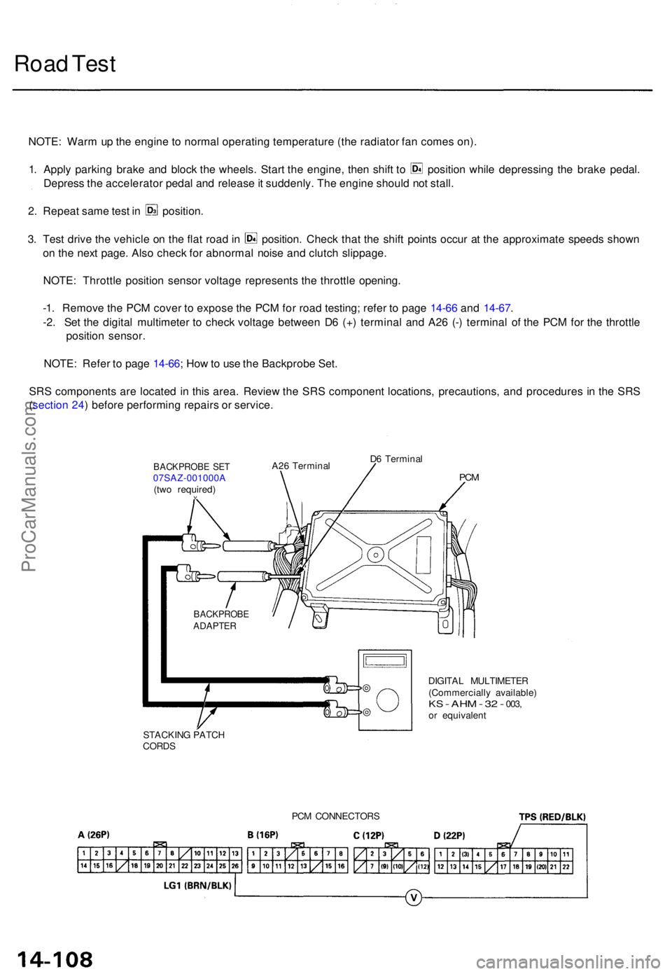
-1 . Remov e th e PC M cove r t o expos e th e PC M fo r roa d testing ; refe r t o pag e 14-6 6 an d 14-67 .
-2 . Se t th e digita l multimete r t o chec k voltag e betwee n D 6 (+ ) termina l an d A2 6 (- ) termina l o f th e PC M fo r th e throttl e
positio n sensor .
NOTE : Refe r t o pag e 14-66 ; Ho w to us e th e Backprob e Set .
SR S component s ar e locate d i n thi s area . Revie w th e SR S componen t locations , precautions , an d procedure s i n th e SR S
( sectio n 24 ) befor e performin g repair s o r service .
DIGITAL MULTIMETE R
(Commerciall y available )
KS - AH M - 32 - 003 ,or equivalen t
STACKIN G PATC H
CORDS
BACKPROB EADAPTER
BACKPROB E SE T07SAZ-001000 A
(tw o required )
v
A26 Termina l D
6 Termina lPCM
PC M CONNECTOR S
ProCarManuals.com
Page 326 of 1771
Road Test
(cont'd)
4. Accelerate to about 35 mph (57 km/h) so the transmission is in 4th, then shift from position to position. The vehi-
cle should immediately begin slowing down from engine braking.
CAUTION: Do not shift from or position to or position at speeds over 63 mph (100 km/h); you may dam-
age the transmission.
5. Check for abnormal noise and clutch slippage in the following positions.
(1st Gear) Position
a. Accelerate from a stop at full throttle. Check that there is no abnormal noise or clutch slippage,
b. Upshifts should not occur with the shift lever in this position.
(2nd Gear) Position
a. Accelerate from a stop at full throttle. Check that there is no abnormal noise or clutch slippage,
b. Upshifts and downshifts should not occur with the shift lever in this position.
(Reverse) Position
Accelerate from a stop at full throttle, and check for abnormal noise and clutch slippage.
6. Test in (Parking) Position
Park the vehicle on slope (approx. 16°), apply the parking brake, and shift into position. Release the brake; the vehi-
cle should not move.ProCarManuals.com
Page 327 of 1771
Stall Speed
Test
CAUTION:
To prevent transmission damage, do not test stall speed for more than 10 seconds at a time.
Do not shift the lever while raising the engine speed.
Be sure to remove the pressure gauge before testing stall speed.
1. Engage the parking brake, and block the front wheels.
2. Connect a tachometer to the engine, and start the engine.
3. Make sure the A/C switch is OFF.
4. After the engine has warmed up to normal operating temperature (the radiator fan comes on), shift into [2] position.
5. Fully depress the brake pedal and accelerator for 6 to 8 seconds, and note engine speed.
6. Allow two minutes for cooling, then repeat the test in , , and positions.
NOTE:
• Stall speed tests should be used for diagnostic purposes only.
• Stall speed should be the same in , and positions.
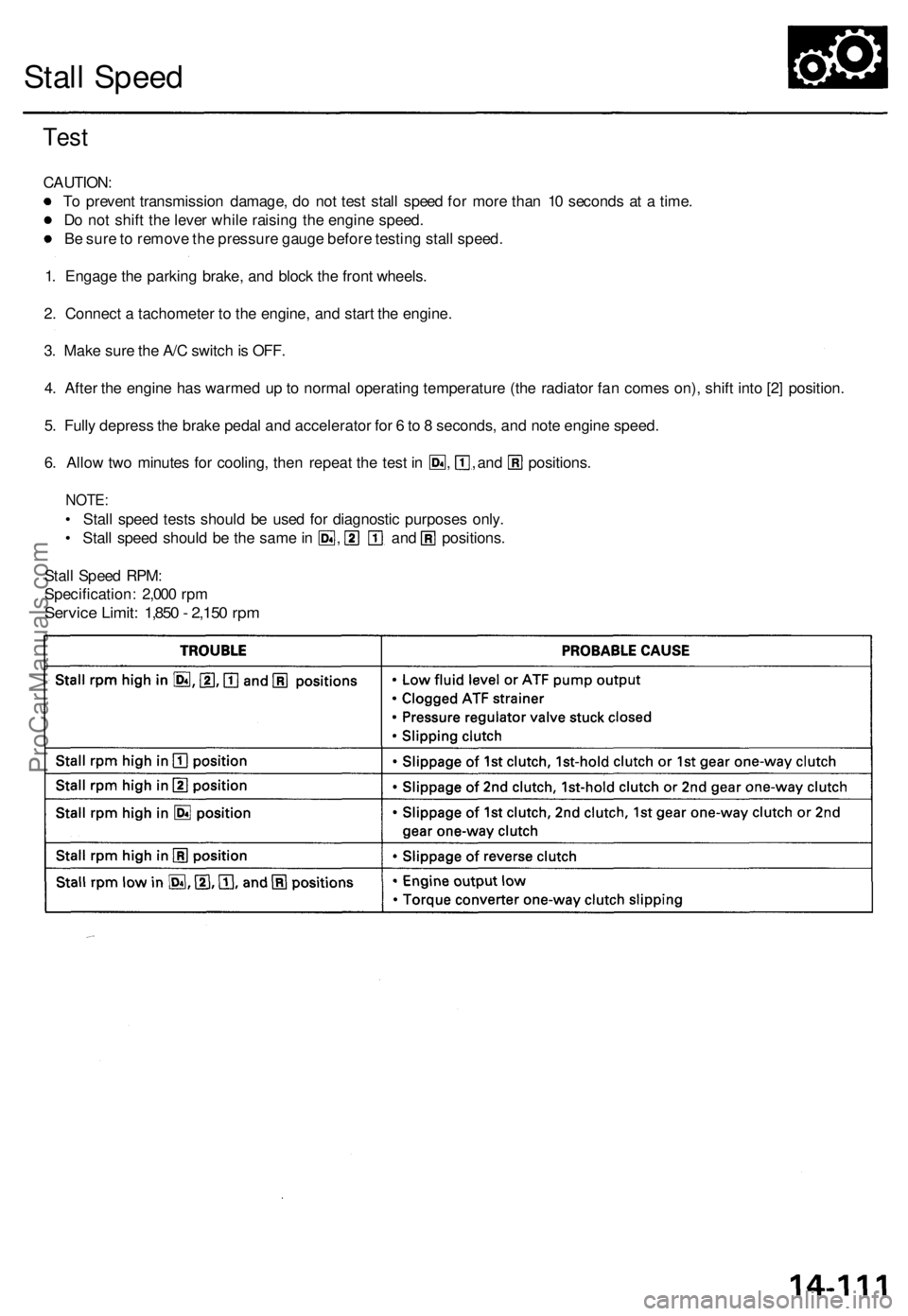
Stall Speed RPM:
Specification: 2,000 rpm
Service Limit: 1,850 - 2,150 rpmProCarManuals.com
Page 328 of 1771
Fluid Level
Checking/Changing
Checking
NOTE: Check the fluid level with the engine at normal
operating temperature (the radiator fan comes on).
1. Park the vehicle on level ground. Turn off the
engine.
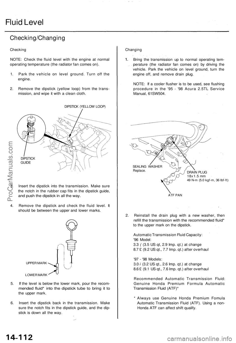
2. Remove the dipstick (yellow loop) from the trans-
mission, and wipe it with a clean cloth.
DIPSTICK (YELLOW LOOP)
DIPSTICK
GUIDE
3. Insert the dipstick into the transmission. Make sure
the notch in the rubber cap fits in the dipstick guide,
and push the dipstick in all the way.
4. Remove the dipstick and check the fluid level. It
should be between the upper and lower marks.
UPPER MARK
LOWER MARK
5. If the level is below the lower mark, pour the recom-
mended fluid* into the dipstick tube to bring it to
the upper mark.
6. Insert the dipstick back in the transmission. Make
sure the notch fits in the dipstick guide, and the dip-
stick is down all the way.
Changing
Bring the transmission up to normal operating tem-
perature (the radiator fan comes on) by driving the
vehicle. Park the vehicle on level ground, turn the
engine off, and remove drain plug.
NOTE: If a cooler flusher is to be used, see flushing
procedure in the '95 - '98 Acura 2.5TL Service
Manual, 61SW504.
SEALING WASHER
Replace.
DRAIN PLUG
18x1.5 mm
49 N-m (5.0 kgf-m, 36 Ibf-ft)
ATF PAN
2. Reinstall the drain plug with a new washer, then
refill the transmission with the recommended fluid*
to the upper mark on the dipstick.
Automatic Transmission Fluid Capacity:
'96 Model:
3.3 ( (3.5 US qt, 2.9 Imp. qt.) at change
8.7 £ (9.2 US qt., 7.7 Imp. qt.) after overhaul
'97 - '98 Models:
3.0 i (3.2 US qt., 2.6 Imp. qt.) at change
8.6 £ (9.1 US qt., 7.6 Imp. qt.) after overhaul
Recommended Automatic Transmission Fluid:
Genuine Honda Premium Formula Automatic
Transmission Fluid (ATF)*
* Always use Genuine Honda Premium Fomula
Automatic Transmission Fluid (ATF). Using a non-
Honda ATF can affect shift qualify.ProCarManuals.com
Page 329 of 1771
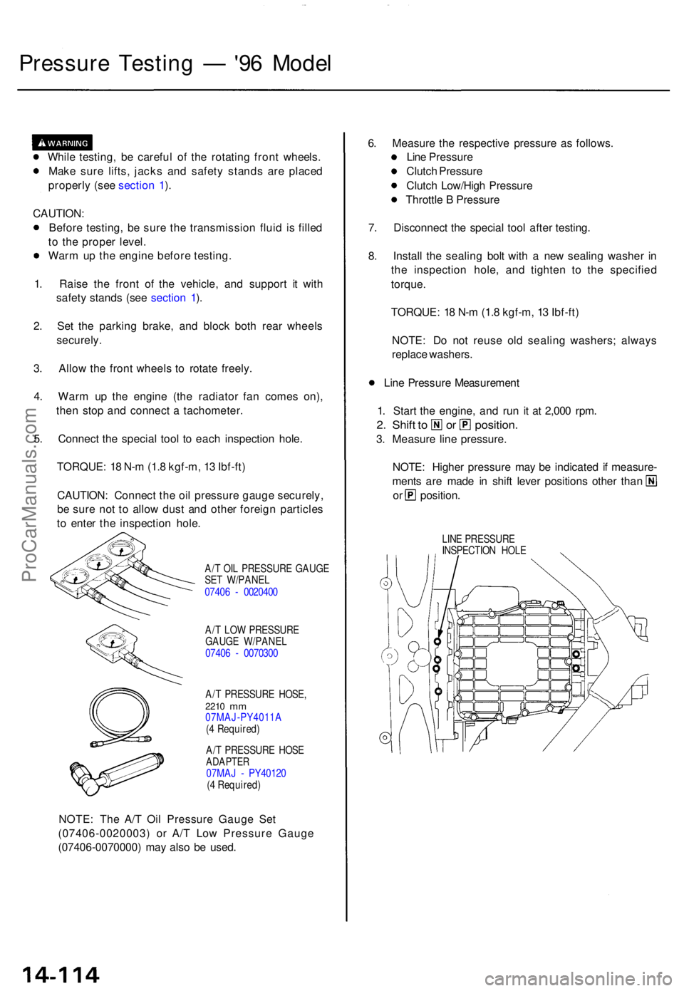
Pressure Testin g — '96 Mode l
While testing , b e carefu l o f th e rotatin g fron t wheels .
Mak e sur e lifts , jack s an d safet y stand s ar e place d
properl y (se e sectio n 1 ).
CAUTION :
Befor e testing , b e sur e th e transmissio n flui d i s fille d
t o th e prope r level .
War m u p th e engin e befor e testing .
1 . Rais e th e fron t o f th e vehicle , an d suppor t i t wit h
safet y stand s (se e sectio n 1 ).
2 . Se t th e parkin g brake , an d bloc k bot h rea r wheel s
securely .
3 . Allo w th e fron t wheel s t o rotat e freely .
4 . War m u p th e engin e (th e radiato r fa n come s on) ,
the n sto p an d connec t a tachometer .
5 . Connec t th e specia l too l t o eac h inspectio n hole .
TORQUE : 1 8 N- m (1. 8 kgf-m , 1 3 Ibf-ft )
CAUTION : Connec t th e oi l pressur e gaug e securely ,
b e sur e no t t o allo w dus t an d othe r foreig n particle s
t o ente r th e inspectio n hole .
A/T OI L PRESSUR E GAUG E
SE T W/PANE L
0740 6 - 002040 0
A/ T LO W PRESSUR E
GAUG E W/PANE L
0740 6 - 007030 0
A/ T PRESSUR E HOSE ,
2210 mm07MAJ-PY4011 A
( 4 Required )
A/ T PRESSUR E HOS E
ADAPTE R07MAJ - PY4012 0
( 4 Required )
NOTE: Th e A/ T Oi l Pressur e Gaug e Se t
(07406-0020003 ) o r A/ T Lo w Pressur e Gaug e
(07406-0070000 ) ma y als o b e used . 6
. Measur e th e respectiv e pressur e a s follows .
Lin e Pressur e
Clutc h Pressur e
Clutc h Low/Hig h Pressur e
Throttl e B Pressur e
7 . Disconnec t th e specia l too l afte r testing .
8 . Instal l th e sealin g bol t wit h a ne w sealin g washe r i n
th e inspectio n hole , an d tighte n t o th e specifie d
torque .
TORQUE : 1 8 N- m (1. 8 kgf-m , 1 3 Ibf-ft )
NOTE : D o no t reus e ol d sealin g washers ; alway s
replac e washers .
Lin e Pressur e Measuremen t
1 . Star t th e engine , an d ru n i t a t 2,00 0 rpm .
2. Shif t t o o r position .
3. Measur e lin e pressure .
NOTE : Highe r pressur e ma y b e indicate d if measure -
ments ar e mad e i n shif t leve r position s othe r tha n
or position .
LINE PRESSUR E
INSPECTIO N HOL E
ProCarManuals.com
Page 330 of 1771
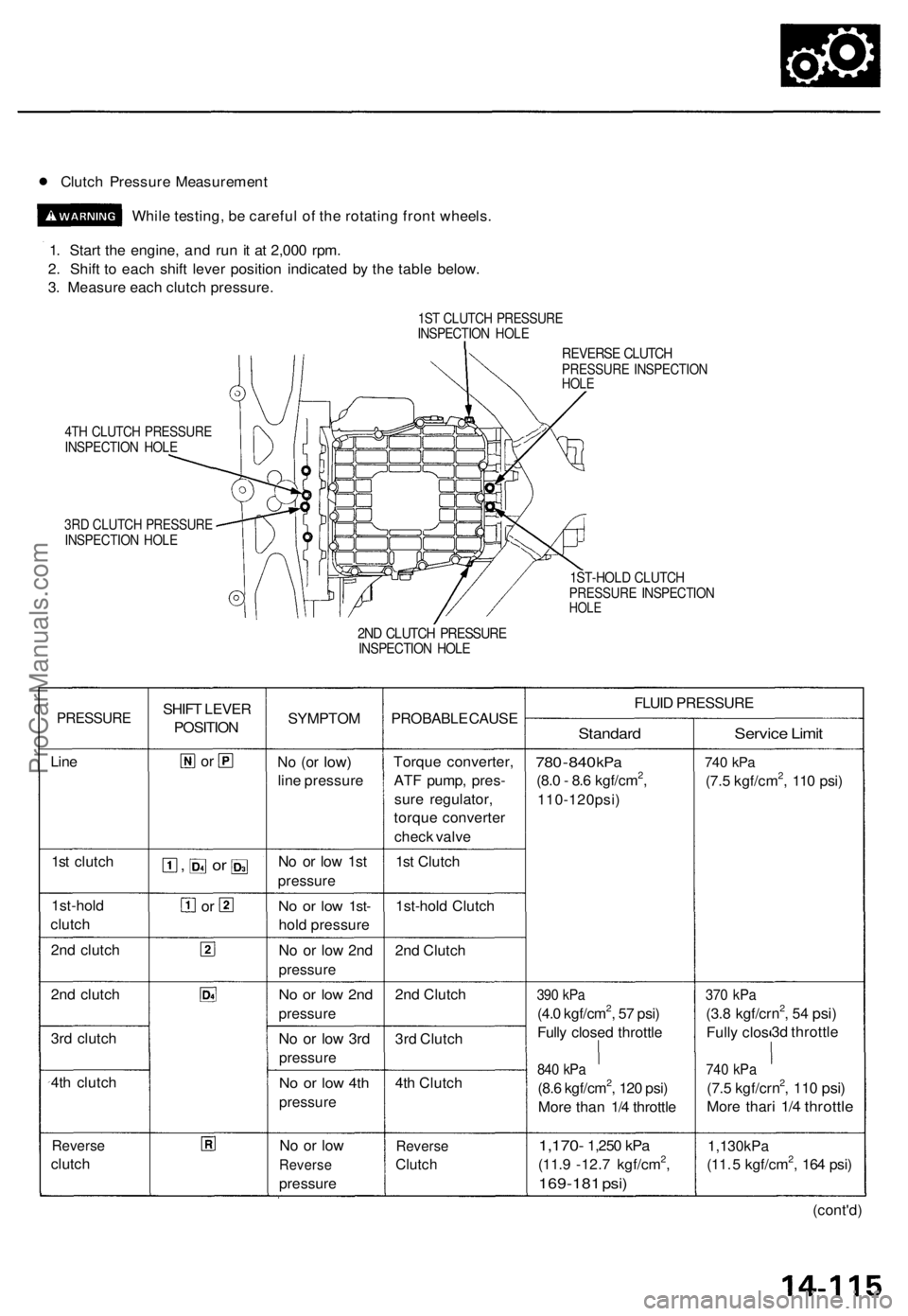
• Clutch Pressur e Measuremen t
Whil e testing , b e carefu l o f th e rotatin g fron t wheels .
1 . Star t th e engine , an d ru n i t a t 2,00 0 rpm .
2 . Shif t t o eac h shif t leve r positio n indicate d b y th e tabl e below .
3 . Measur e eac h clutc h pressure .
1ST CLUTC H PRESSUR EINSPECTIO N HOL E
4TH CLUTC H PRESSUR EINSPECTIO N HOL E
3RD CLUTC H PRESSUR EINSPECTIO N HOL E
REVERS E CLUTC HPRESSUR E INSPECTIO NHOLE
1ST-HOL D CLUTC HPRESSUR E INSPECTIO NHOLE
2ND CLUTC H PRESSUR EINSPECTIO N HOL E
PRESSUR E
Line
1s t clutc h
1st-hol d
clutc h
2n d clutc h
2n d clutc h
3r d clutc h
4t h clutc h
Revers e
clutch SHIF
T LEVE R
POSITIO N
or
, or
or
SYMPTO M
No (o r low )
line pressur e
No o r lo w 1s t
pressur e
No o r lo w 1st -
hold pressur e
No o r lo w 2n d
pressur e
No o r lo w 2n d
pressur e
No o r lo w 3r d
pressur e
No o r lo w 4t h
pressur e
No o r lo w
Revers e
pressur e
PROBABL E CAUS E
Torqu e converter ,
AT F pump , pres -
sur e regulator ,
torqu e converte r
chec k valv e
1s t Clutc h
1st-hol d Clutc h
2n d Clutc h
2n d Clutc h
3r d Clutc h
4t h Clutc h
Revers e
Clutch
FLUID PRESSUR E
Standard
780 - 84 0 kP a
(8.0 - 8. 6 kgf/cm2,
110-120psi )
390 kP a
(4.0 kgf/cm2, 5 7 psi )
Full y close d throttl e
840 kP a
(8.6 kgf/cm2, 12 0 psi )
Mor e tha n 1/ 4 throttl e
1,170- 1,250 kPa
(11. 9 -12. 7 kgf/cm2,
169-18 1 psi )
Servic e Limi t
740 kP a
(7.5 kgf/cm2, 11 0 psi )
370 kP a
(3.8 kgf/c r
Full y clo s
740 kP a
(7.5 kgf/c r
Mor e tha r
n2, 5 4 psi )
3d throttl e
n2, 11 0 psi )
i 1/ 4 throttl e
1,130kP a
(11. 5 kgf/cm2, 16 4 psi )
(cont'd )
ProCarManuals.com
Page 331 of 1771
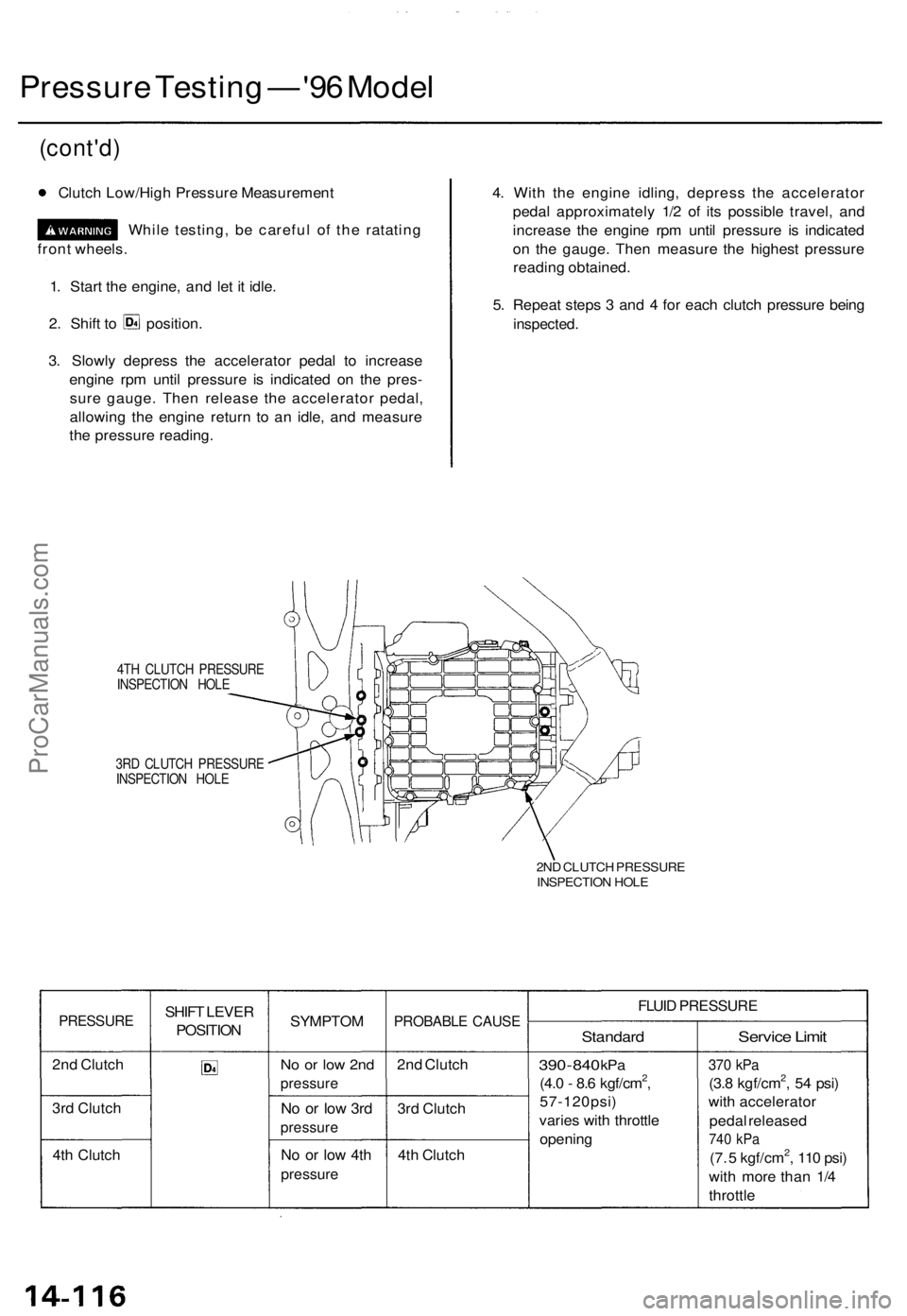
Pressure Testing — '96 Model
3. Slowly depress the accelerator pedal to increase
engine rpm until pressure is indicated on the pres-
sure gauge. Then release the accelerator pedal,
allowing the engine return to an idle, and measure
the pressure reading.
4. With the engine idling, depress the accelerator
pedal approximately 1/2 of its possible travel, and
increase the engine rpm until pressure is indicated
on the gauge. Then measure the highest pressure
reading obtained.
5. Repeat steps 3 and 4 for each clutch pressure being
inspected.
4TH CLUTCH PRESSURE
INSPECTION HOLE
3RD CLUTCH PRESSURE
INSPECTION HOLE
2ND CLUTCH PRESSURE
INSPECTION HOLE
PRESSURE
2nd Clutch
3rd Clutch
4th Clutch
SHIFT LEVER
POSITION
SYMPTOM
No or low 2nd
pressure
No or low 3rd
pressure
No or low 4th
pressure
PROBABLE CAUSE
2nd Clutch
3rd Clutch
4th Clutch
FLUID PRESSURE
Standard
390
-
840
kPa
(4.0 - 8.6 kgf/cm2,
57-120psi)
varies with throttle
opening
Service Limit
370 kPa
(3.8 kgf/cm2, 54 psi)
with accelerator
pedal released
740 kPa
(7. 5 kgf/cm2, 110 psi)
with more than 1/4
throttle
1. Start the engine, and let it idle.
(cont'd)
Clutch Low/High Pressure Measurement
2. Shift to position.
front wheels.
While testing, be careful of the ratatingProCarManuals.com
Page 332 of 1771
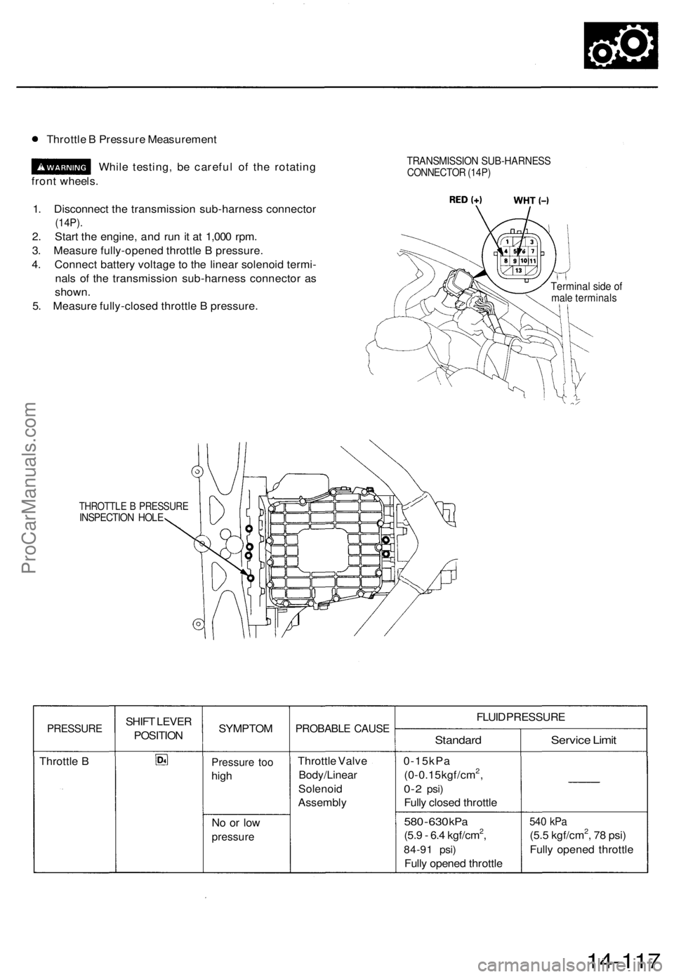
Throttle B Pressure Measurement
While testing, be careful of the rotating
front wheels.
1. Disconnect the transmission sub-harness connector
(14P).
2. Start the engine, and run it at 1,000 rpm.
3. Measure fully-opened throttle B pressure.
4. Connect battery voltage to the linear solenoid termi-
nals of the transmission sub-harness connector as
shown.
5. Measure fully-closed throttle B pressure.
TRANSMISSION SUB-HARNESS
CONNECTOR (14P)
Terminal side of
male terminals
THROTTLE B PRESSURE
INSPECTION HOLE
PRESSURE
Throttle B
SHIFT LEVER
POSITION
SYMPTOM
Pressure too
high
No or low
pressure
PROBABLE CAUSE
Throttle Valve
Body/Linear
Solenoid
Assembly
FLUID PRESSURE
Standard
0-15kPa
(0-0.15kgf/cm2,
0-2
psi)
Fully closed throttle
580
-
630
kPa
(5.9 - 6.4 kgf/cm2,
84-91 psi)
Fully opened throttle
Service Limit
540 kPa
(5.5 kgf/cm2, 78 psi)
Fully opened throttle
14-117ProCarManuals.com
Page 334 of 1771
![ACURA TL 1995 Service Repair Manual
6. Disconnect the transmission sub-harness connector (14P).
7. Start the engine, and run it at 2,000 rpm.
TRANSMISSION SUB-HARNESS
CONNECTOR (14P)
8. Shift to the [HI or [P] position, and measure ACURA TL 1995 Service Repair Manual
6. Disconnect the transmission sub-harness connector (14P).
7. Start the engine, and run it at 2,000 rpm.
TRANSMISSION SUB-HARNESS
CONNECTOR (14P)
8. Shift to the [HI or [P] position, and measure](/img/32/56993/w960_56993-333.png)
6. Disconnect the transmission sub-harness connector (14P).
7. Start the engine, and run it at 2,000 rpm.
TRANSMISSION SUB-HARNESS
CONNECTOR (14P)
8. Shift to the [HI or [P] position, and measure line pressure at fully-opened throttle.
9. Connect battery voltage to the linear solenoid terminals of the transmission sub-harness connector as shown.
10. Measure line pressure at fully-closed throttle.
If line pressure is out of specification, check and repair the probable cause in the table below.
PRESSURE
Line
SHIFT LEVER
POSITION
or
SYMPTOM
No (or
low)
line pressure
PROBABLE CAUSE
Torque converter,
ATF pump, pres-
sure regulator.
torque converter
check valve
FLUID PRESSURE
Standard
520 kPa
(5.3 kgf/cm2, 75 psi)
Fully closed throttle
|
910 kPa
(9.3 kgf/cm2, 130 psi)
Fully opened throttle
Service Limit
500 kPa
(5.1 kgf/cm2, 73 psi)
Fully closed throttle
790 kPa
(8.1 kgf/cm2, 120 psi)
Fully opened throttle
11. Stop the engine, and connect the transmission sub-harness connector (14P).
12. Disconnect the special tool from line pressure inspection hole, and connect the special tool to each inspection hole.
13. Start the engine, and run it at 2,000 rpm.
(cont'd)ProCarManuals.com
Page 344 of 1771
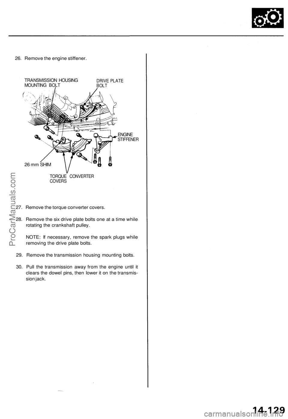
26. Remove the engine stiffener.
TRANSMISSION HOUSING
MOUNTING BOLT
DRIVE PLATE
BOLT
ENGINE
STIFFENER
TORQUE CONVERTER
COVERS
27. Remove the torque converter covers.
28. Remove the six drive plate bolts one at a time while
rotating the crankshaft pulley.
NOTE: If necessary, remove the spark plugs while
removing the drive plate bolts.
29. Remove the transmission housing mounting bolts.
30. Pull the transmission away from the engine until it
clears the dowel pins, then lower it on the transmis-
sion jack.
26 mm SHIMProCarManuals.com