gearbox ACURA TL 1995 Service Owner's Manual
[x] Cancel search | Manufacturer: ACURA, Model Year: 1995, Model line: TL, Model: ACURA TL 1995Pages: 1771, PDF Size: 62.49 MB
Page 1192 of 1771
Steering Gearbo x
Remova l (cont'd )
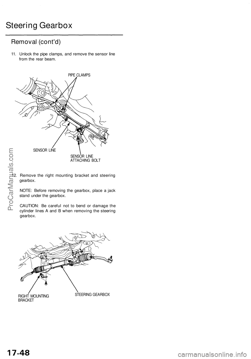
11. Unloc k th e pip e clamps , an d remov e th e senso r lin e
fro m th e rea r beam .
PIPE CLAMP S
SENSO R LIN E
SENSOR LIN E
ATTACHIN G BOL T
12. Remov e th e righ t mountin g bracke t an d steerin g
gearbox .
NOTE : Befor e removin g th e gearbox , plac e a jac k
stan d unde r th e gearbox .
CAUTION : B e carefu l no t t o ben d o r damag e th e
cylinde r line s A an d B whe n removin g th e steerin g
gearbox .
RIGHT MOUNTIN GBRACKET STEERIN
G GEARBO X
ProCarManuals.com
Page 1193 of 1771
Disassembly
Steering Rac k Disassembl y
NOTE:
• Befor e disassemblin g th e steerin g gearbox , was h i t
of f wit h solven t an d a brush .
• D o no t di p seal s an d O-ring s i n solvent .
1 . Remov e th e steerin g gearbo x (se e pag e 17-47 ).
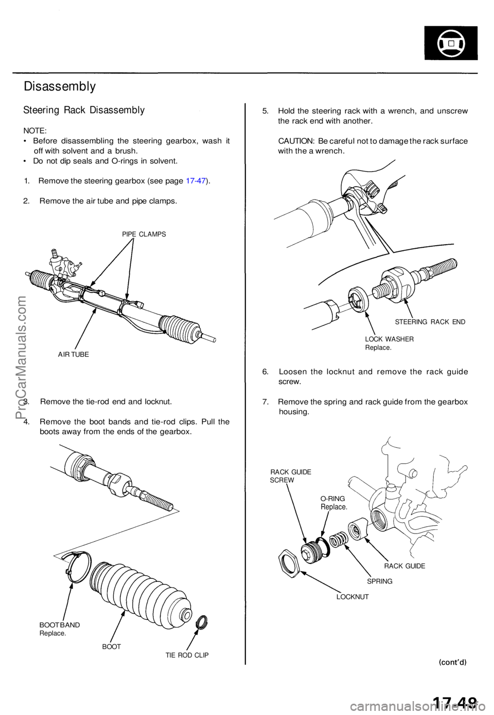
2 . Remov e th e ai r tub e an d pip e clamps .
PIPE CLAMP S
AIR TUB E
3. Remov e th e tie-ro d en d an d locknut .
4 . Remov e th e boo t band s an d tie-ro d clips . Pul l th e
boot s awa y fro m th e end s o f th e gearbox.
BOO T BAN DReplace .
BOOTTIE RO D CLI P
5. Hol d th e steerin g rac k wit h a wrench , an d unscre w
th e rac k en d wit h another .
CAUTION : B e carefu l no t t o damag e th e rac k surfac e
wit h th e a wrench .
STEERIN G RAC K EN D
LOC K WASHE RReplace.
6. Loose n th e locknu t an d remov e th e rac k guid e
screw .
7 . Remov e th e sprin g an d rac k guid e fro m th e gearbo x
housing .
RACK GUID ESCRE W
RACK GUID E
SPRIN G
LOCKNU T
O-RINGReplace .
ProCarManuals.com
Page 1194 of 1771
Steering Gearbo x
Disassembl y (cont'd )
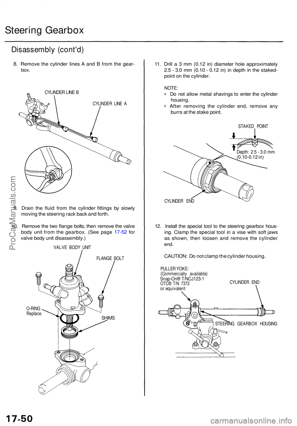
8. Remov e th e cylinde r line s A an d B fro m th e gear -
box.
CYLINDE R LIN E B
CYLINDE R LIN E A
9. Drai n th e flui d fro m th e cylinde r fitting s b y slowl y
movin g th e steerin g rac k bac k an d forth .
10 . Remov e th e tw o flang e bolts , the n remov e th e valv e
bod y uni t fro m th e gearbox . (Se e pag e 17-5 2 fo r
valv e bod y uni t disassembly. )
VALVE BOD Y UNI T
FLANG E BOL T
O-RIN G
Replace .
11. Dril l a 3 mm (0.1 2 in ) diamete r hol e approximatel y
2. 5 - 3. 0 m m (0.1 0 - 0.1 2 in ) i n dept h in th e staked -
poin t o n th e cylinder .
NOTE:
• D o no t allo w meta l shaving s t o ente r th e cylinde r
housing .
• Afte r removin g th e cylinde r end , remov e an y
burr s a t th e stak e point .
STAKE D POIN T
CYLINDE R EN D
12. Instal l th e specia l too l t o th e steerin g gearbo x hous -
ing . Clam p th e specia l too l i n a vis e wit h sof t jaw s
a s shown , the n loose n an d remov e th e cylinde r
end.
CAUTION : D o no t clam p th e cylinde r housing .
PULLER YOKE :
(Commerciall y available )
Snap-On® T/NCJ123- 1OTC® T/ N 737 2or equivalen t
CYLINDER EN D
STEERIN G GEARBO X HOUSIN G
SHIMS
Depth : 2. 5 - 3. 0 m m(0.10-0.1 2 in )
ProCarManuals.com
Page 1195 of 1771
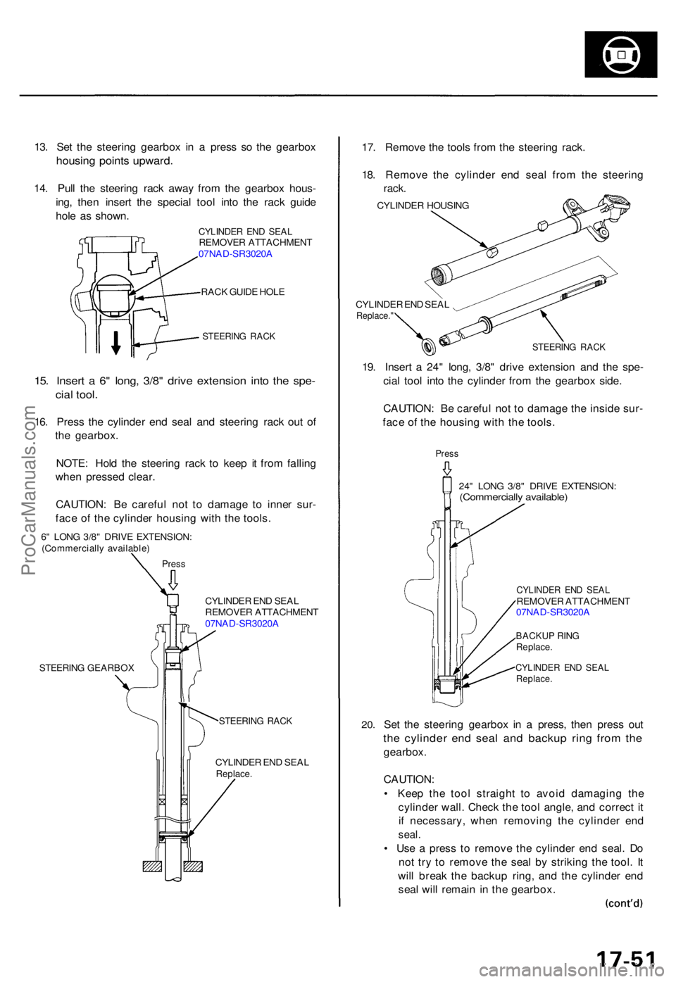
13. Se t th e steerin g gearbo x i n a pres s s o th e gearbo x
housing point s upward .
14. Pul l th e steerin g rac k awa y fro m th e gearbo x hous -
ing , the n inser t th e specia l too l int o th e rac k guid e
hol e a s shown .
CYLINDE R EN D SEA LREMOVE R ATTACHMEN T
07NA D-SR3020 A
RAC K GUID E HOL E
STEERIN G RAC K
15. Inser t a 6 " long , 3/8 " driv e extensio n int o th e spe -
cial tool .
16. Pres s th e cylinde r en d sea l an d steerin g rac k ou t o f
th e gearbox .
NOTE : Hol d th e steerin g rac k t o kee p i t fro m fallin g
whe n presse d clear .
CAUTION : B e carefu l no t t o damag e t o inne r sur -
fac e o f th e cylinde r housin g wit h th e tools .
6" LON G 3/8 " DRIV E EXTENSION :(Commerciall y available )
Press
CYLINDE R EN D SEA L
REMOVE R ATTACHMEN T
07NA D-SR3020 A
STEERIN G GEARBO X
STEERING RAC K
CYLINDE R EN D SEA LReplace .
17. Remov e th e tool s fro m th e steerin g rack .
18 . Remov e th e cylinde r en d sea l fro m th e steerin g
rack.
CYLINDE R HOUSIN G
CYLINDE R EN D SEA L
Replace. "
STEERIN G RAC K
19. Inser t a 24 " long , 3/8 " driv e extensio n an d th e spe -
cia l too l int o th e cylinde r fro m th e gearbo x side .
CAUTION : B e carefu l no t t o damag e th e insid e sur -
fac e o f th e housin g wit h th e tools .
Press
24" LON G 3/8 " DRIV E EXTENSION :(Commercially available )
20.
CYLINDE R EN D SEA LREMOVE R ATTACHMEN T
07NA D-SR3020 A
BACKU P RIN GReplace .
CYLINDE R EN D SEA LReplace .
Set th e steerin g gearbo x i n a press , the n pres s ou t
the cylinde r en d sea l an d backu p rin g fro m th e
gearbox .
CAUTION :
• Kee p th e too l straigh t t o avoi d damagin g th e
cylinde r wall . Chec k th e too l angle , an d correc t i t
i f necessary , whe n removin g th e cylinde r en d
seal .
• Us e a pres s t o remov e th e cylinde r en d seal . D o
no t tr y t o remov e th e sea l b y strikin g th e tool . I t
wil l brea k th e backu p ring , an d th e cylinde r en d
sea l wil l remai n in th e gearbox .
ProCarManuals.com
Page 1206 of 1771
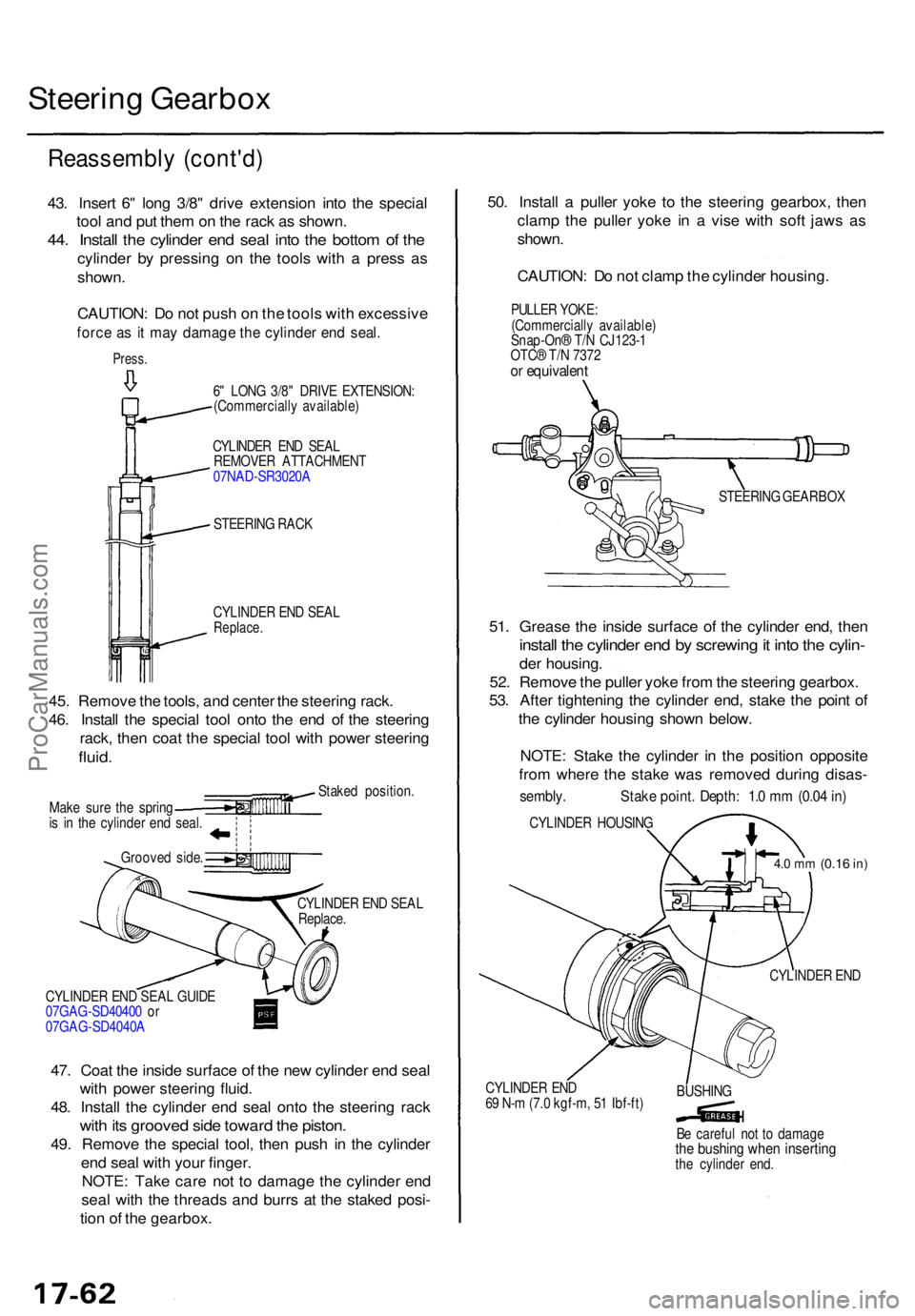
Steering Gearbo x
Reassembl y (cont'd )
43. Inser t 6 " lon g 3/8 " driv e extensio n int o th e specia l
too l an d pu t the m on th e rac k a s shown .
44. Instal l th e cylinde r en d sea l int o th e botto m o f th e
cylinde r b y pressin g o n th e tool s wit h a pres s a s
shown .
CAUTION : D o no t pus h o n th e tool s wit h excessiv e
force a s i t ma y damag e th e cylinde r en d seal .
Press .
STEERIN G RAC K
CYLINDE R EN D SEA L
Replace .
a
45. Remov e th e tools , an d cente r th e steerin g rack .
46 . Instal l th e specia l too l ont o th e en d o f th e steerin g
rack , the n coa t th e specia l too l wit h powe r steerin g
fluid.
Stake d position .
Mak e sur e th e sprin g
i s i n th e cylinde r en d seal .
Groove d side .
CYLINDER EN D SEA L
Replace .
CYLINDE R EN D SEA L GUID E
07GA G-SD4040 0 o r
07GA G-SD4040 A
47. Coa t th e insid e surfac e o f th e ne w cylinde r en d sea l
wit h powe r steerin g fluid .
48 . Instal l th e cylinde r en d sea l ont o th e steerin g rac k
with it s groove d sid e towar d th e piston .
49. Remov e th e specia l tool , the n pus h i n th e cylinde r
en d sea l wit h you r finger.
NOTE : Tak e car e no t t o damag e th e cylinde r en d
sea l wit h th e thread s an d burr s a t th e stake d posi -
tio n o f th e gearbox . 50
. Instal l a pulle r yok e t o th e steerin g gearbox , the n
clam p th e pulle r yok e i n a vis e wit h sof t jaw s a s
shown .
CAUTION : D o no t clam p th e cylinde r housing .
51 . Greas e th e insid e surfac e o f th e cylinde r end , the n
instal l th e cylinde r en d b y screwin g it int o th e cylin -
der housing .
52 . Remov e th e pulle r yok e fro m th e steerin g gearbox .
53 . Afte r tightenin g th e cylinde r end , stak e th e poin t o f
th e cylinde r housin g show n below .
NOTE : Stak e th e cylinde r i n th e positio n opposit e
fro m wher e th e stak e wa s remove d durin g disas -
sembly . Stak e point . Depth : 1. 0 m m (0.0 4 in )
CYLINDE R HOUSIN G
4.0 m m (0.1 6 in)
CYLINDE R EN D
CYLINDE R EN D
6 9 N- m (7. 0 kgf-m , 5 1 Ibf-ft ) BUSHIN
G
B e carefu l no t t o damag e
the bushin g whe n insertin gthe cylinde r end .
CYLINDE
R EN D SEA L
REMOVE R ATTACHMEN T
07NA D-SR3020 A
6
" LON G 3/8 " DRIV E EXTENSION :
(Commerciall y available ) PULLE
R YOKE :
(Commerciall y available )
Snap-On ® T/ N CJ123- 1
OTC ® T/ N 737 2
or equivalen t
STEERING GEARBO X
ProCarManuals.com
Page 1207 of 1771
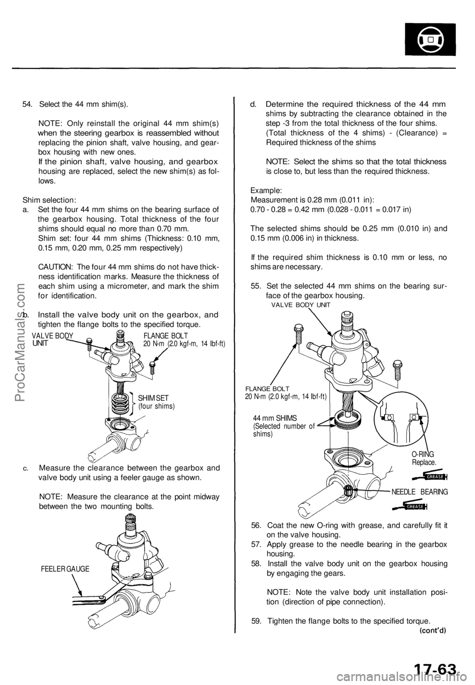
54. Selec t th e 4 4 m m shim(s) .
NOTE : Onl y reinstal l th e origina l 4 4 m m shim(s )
when th e steerin g gearbo x i s reassemble d withou t
replacin g th e pinio n shaft , valv e housing , an d gear -
bo x housin g wit h ne w ones .
If th e pinio n shaft , valv e housing , an d gearbo x
housing ar e replaced , selec t th e ne w shim(s ) a s fol -
lows .
Shi m selection :
a . Se t th e fou r 4 4 m m shim s o n th e bearin g surfac e o f
th e gearbo x housing . Tota l thicknes s o f th e fou r
shim s shoul d equa l n o mor e tha n 0.7 0 mm .
Shi m set : fou r 4 4 m m shim s (Thickness : 0.1 0 mm ,
0.1 5 mm , 0.2 0 mm , 0.2 5 m m respectively )
CAUTION : Th e fou r 4 4 m m shim s d o no t hav e thick -
nes s identificatio n marks . Measur e th e thicknes s o f
eac h shi m usin g a micrometer , an d mar k th e shi m
fo r identification .
b. Instal l th e valv e bod y uni t o n th e gearbox , an d
tighte n th e flang e bolt s t o th e specifie d torque .
SHIM SET(fou r shims )
c.Measur e th e clearanc e betwee n th e gearbo x an d
valv e bod y uni t usin g a feele r gaug e a s shown .
NOTE : Measur e th e clearanc e a t th e poin t midwa y
betwee n th e tw o mountin g bolts .
FEELE R GAUG E
d. Determin e th e require d thicknes s o f th e 4 4 m m
shim s b y subtractin g th e clearanc e obtaine d i n th e
ste p - 3 fro m th e tota l thicknes s o f th e fou r shims .
(Tota l thicknes s o f th e 4 shims ) - (Clearance ) =
Require d thicknes s o f th e shim s
NOTE : Selec t th e shim s s o tha t th e tota l thicknes s
is clos e to , bu t les s tha n th e require d thickness .
Example:
Measuremen t i s 0.2 8 m m (0.01 1 in) :
0.7 0 - 0.2 8 = 0.4 2 m m (0.02 8 - 0.01 1 = 0.01 7 in )
Th e selecte d shim s shoul d b e 0.2 5 m m (0.01 0 in ) an d
0.1 5 m m (0.00 6 in ) i n thickness .
I f th e require d shi m thicknes s i s 0.1 0 m m o r less , n o
shim s ar e necessary .
55 . Se t th e selecte d 4 4 m m shim s o n th e bearin g sur -
fac e o f th e gearbo x housing .
FLANGE BOL T20 N- m (2. 0 kgf-m , 1 4 Ibf-ft )
44 m m SHIM S(Selecte d numbe r o f
shims )
56. Coa t th e ne w O-rin g wit h grease , an d carefull y fi t i t
o n th e valv e housing .
57 . Appl y greas e t o th e needl e bearin g i n th e gearbo x
housing .
58 . Instal l th e valv e bod y uni t o n th e gearbo x housin g
b y engagin g th e gears .
NOTE : Not e th e valv e bod y uni t installatio n posi -
tio n (directio n o f pip e connection) .
59 . Tighte n th e flang e bolt s t o th e specifie d torque .
VALVE BOD YUNITFLANG E BOL T
2 0 N- m (2. 0 kgf-m , 1 4 Ibf-ft )
NEEDLE BEARIN G
O-RIN
G
Replace .
VALVE BOD Y UNI T
ProCarManuals.com
Page 1211 of 1771
Steering Gearbo x
Installatio n
CAUTION: B e carefu l no t t o ben d o r damag e th e cylin -
de r lin e A an d B whe n installin g th e gearbox .
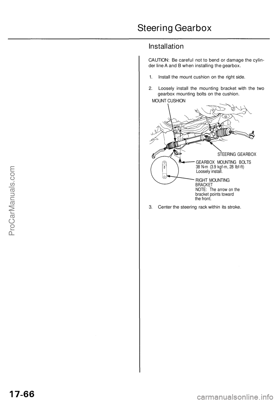
1 . Instal l th e moun t cushio n o n th e righ t side .
2 . Loosel y instal l th e mountin g bracke t wit h th e tw o
gearbo x mountin g bolt s o n th e cushion .
MOUNT CUSHIO N
STEERIN G GEARBO X
GEARBO X MOUNTIN G BOLT S
3 8 N- m (3. 9 kgf-m , 2 8 Ibf-ft )
Loosel y install .
RIGHT MOUNTIN GBRACKETNOTE: Th e arro w o n th ebracke t point s towar dthe front .
3. Cente r th e steerin g rac k withi n it s stroke .
ProCarManuals.com
Page 1213 of 1771
Steering Gearbo x
Installatio n (cont'd )
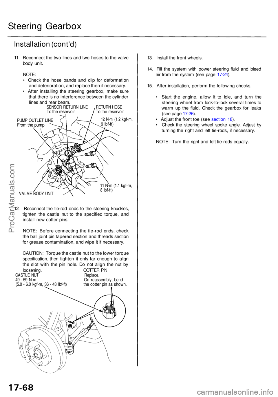
11. Reconnec t th e tw o line s an d tw o hose s t o th e valv e
body unit .
NOTE :
• Chec k th e hos e band s an d cli p fo r deformatio n
an d deterioration , an d replac e the n if necessary .
• Afte r installin g th e steerin g gearbox , mak e sur e
tha t ther e is n o interferenc e betwee n th e cylinde r
line s an d rea r beam .
PUMP OUTLE T LIN EFrom th e pum p
12 N- m (1. 2 kgf-m ,9 Ibf-ft )
VALV E BOD Y UNI T
11 N- m (1. 1 kgf-m ,8 Ibf-ft )
12. Reconnec t th e tie-ro d end s t o th e steerin g knuckles ,
tighte n th e castl e nu t t o th e specifie d torque , an d
instal l ne w cotte r pins .
NOTE : Befor e connectin g th e tie-ro d ends , chec k
th e bal l join t pi n tapere d sectio n an d thread s sectio n
fo r greas e contamination , an d wip e it i f necessary .
CAUTION : Torqu e th e castl e nu t t o th e lowe r torqu e
specification , the n tighte n it onl y fa r enoug h t o alig n
th e slo t wit h th e pi n hole . D o no t alig n th e nu t b y
loosening . COTTER PI NCASTL E NU T Replace.49 - 5 9 N- m O n reassembly , ben d(5.0 - 6. 0 kgf-m , 3 6 - 4 3 Ibf-ft ) th e cotte r pi n a s shown .
13. Instal l th e fron t wheels .
14 . Fil l th e syste m wit h powe r steerin g flui d an d blee d
ai r fro m th e syste m (se e pag e 17-24 ).
15 . Afte r installation , perfor m th e followin g checks .
• Star t th e engine , allo w i t t o idle , an d tur n th e
steerin g whee l fro m lock-to-loc k severa l time s t o
war m u p th e fluid . Chec k th e gearbo x fo r leak s
(se e pag e 17-26 ).
• Adjus t th e fron t to e (se e sectio n 18 ).
• Chec k th e steerin g whee l spok e angle . Adjus t b y
turnin g th e righ t an d lef t tie-rods , i f necessary .
NOTE : Tur n th e righ t an d lef t tie-rod s equally .
SENSO R RETUR N LIN ETo th e reservoi rRETURN HOS ETo th e reservoi r
ProCarManuals.com
Page 1436 of 1771
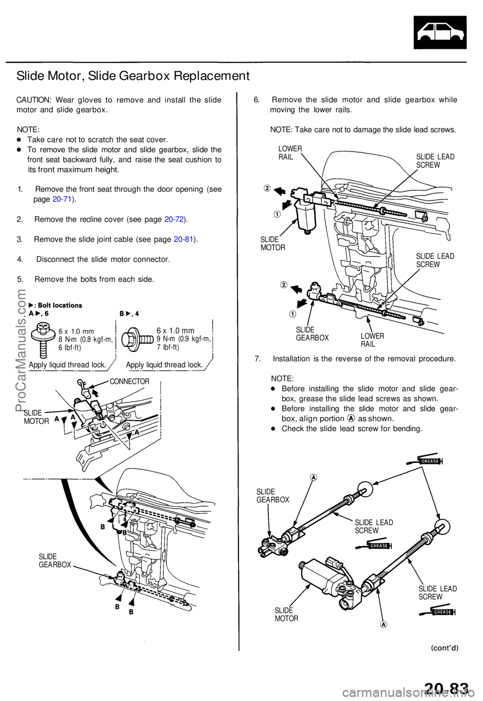
Slide Motor , Slid e Gearbo x Replacemen t
CAUTION: Wea r glove s t o remov e an d instal l th e slid e
moto r an d slid e gearbox .
NOTE :
Tak e car e no t t o scratc h th e sea t cover .
T o remov e th e slid e moto r an d slid e gearbox , slid e th e
fron t sea t backwar d fully , an d rais e th e sea t cushio n t o
its fron t maximu m height .
1. Remov e th e fron t sea t throug h th e doo r openin g (se e
pag e 20-71 ).
2 . Remov e th e reclin e cove r (se e pag e 20-72 ).
3 . Remov e th e slid e join t cabl e (se e pag e 20-81 ).
4 . Disconnec t th e slid e moto r connector .
5 . Remov e th e bolt s fro m eac h side .
6 x 1. 0 m m8 N- m (0. 8 kgf-m ,
6 Ibf-ft )6 x 1. 0 m m9 N- m (0. 9 kgf-m ,
7 Ibf-ft )
SLID E
GEARBO X
6. Remov e th e slid e moto r an d slid e gearbo x whil e
movin g th e lowe r rails .
NOTE : Tak e car e no t t o damag e th e slid e lea d screws .
LOWERRAILSLID E LEA D
SCRE W
SLID E
MOTO R
SLIDE
GEARBO X LOWE
R
RAIL
7. Installatio n i s th e revers e o f th e remova l procedure .
NOTE:
Before installin g th e slid e moto r an d slid e gear -
box , greas e th e slid e lea d screw s a s shown .
Befor e installin g th e slid e moto r an d slid e gear -
box, alig n portio n a s shown .
Check th e slid e lea d scre w fo r bending .
SLIDEGEARBO X
SLIDE
MOTO R SLID
E LEA D
SCRE W
SLID E
MOTO R
CONNECTO R
SLIDE LEA D
SCRE W
SLIDE LEA D
SCRE W
Apply liqui d threa d lock .Apply liqui d threa d lock .
ProCarManuals.com
Page 1437 of 1771
Front Seat
Slide Motor, Slide Gearbox
Replacement (cont'd)
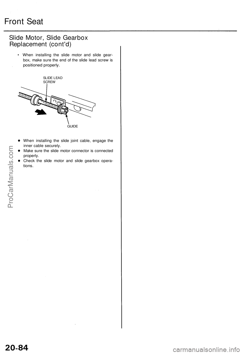
• When installing the slide motor and slide gear-
box, make sure the end of the slide lead screw is
positioned properly.
SLIDE LEAD
SCREW
GUIDE
When installing the slide joint cable, engage the
inner cable securely.
Make sure the slide motor connector is connected
properly.
Check the slide motor and slide gearbox opera-
tions.ProCarManuals.com