radiator ACURA TL 1995 Service Repair Manual
[x] Cancel search | Manufacturer: ACURA, Model Year: 1995, Model line: TL, Model: ACURA TL 1995Pages: 1771, PDF Size: 62.49 MB
Page 48 of 1771
Engine Removal/Installatio n
Removal (cont'd )
30. Remov e th e radiato r cap .
Us e car e whe n removin g th e radiato r
ca p to avoi d scaldin g b y ho t coolan t o r steam .
31 . Rais e th e hois t t o ful l height .
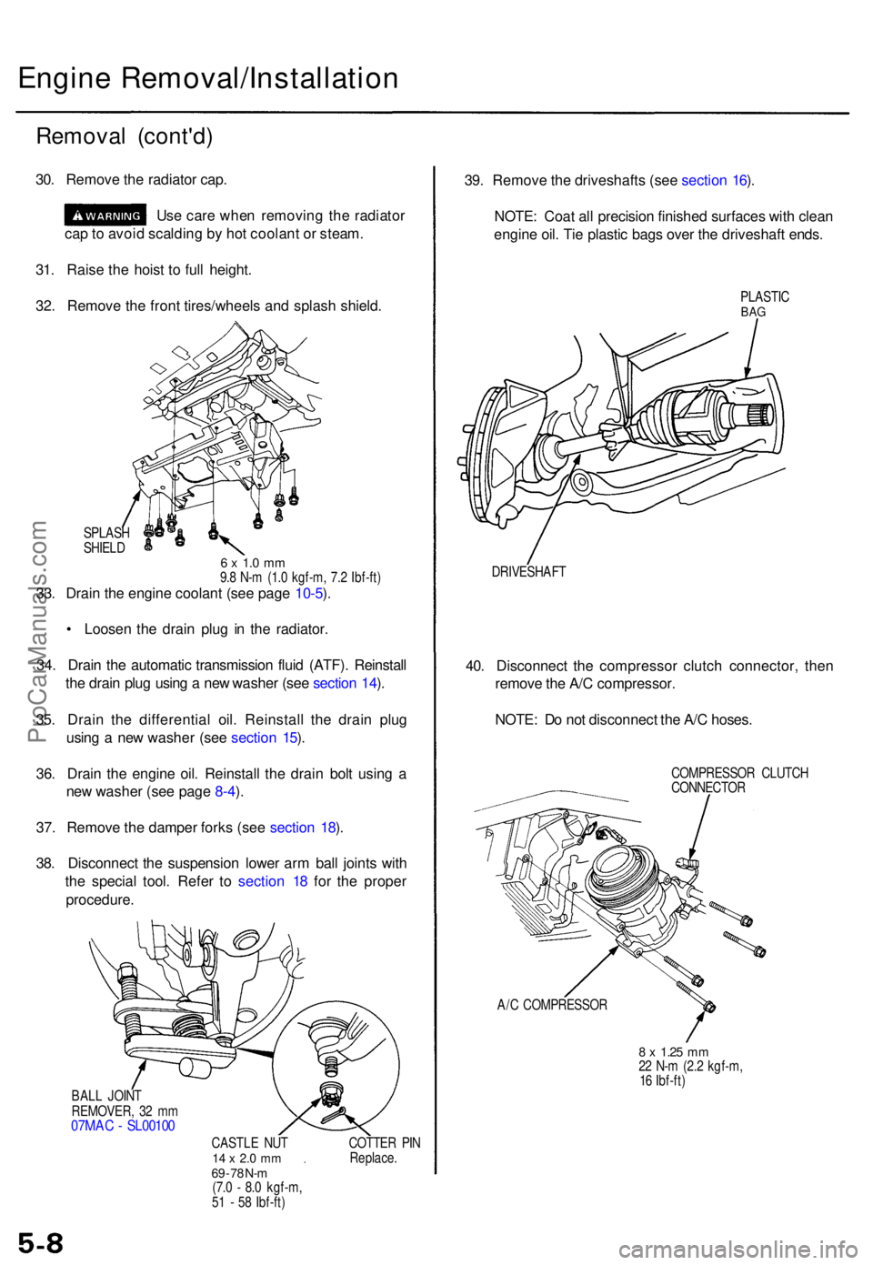
32 . Remov e th e fron t tires/wheel s an d splas h shield .
SPLAS H
SHIEL D
6 x 1. 0 m m9.8 N- m (1. 0 kgf-m , 7. 2 Ibf-ft )33. Drai n th e engin e coolan t (se e pag e 10-5 ).
• Loose n th e drai n plu g i n th e radiator .
34 . Drai n th e automati c transmissio n flui d (ATF) . Reinstal l
th e drai n plu g usin g a ne w washe r (se e sectio n 14 ).
35 . Drai n th e differentia l oil . Reinstal l th e drai n plu g
usin g a ne w washe r (se e sectio n 15 ).
36 . Drai n th e engin e oil . Reinstal l th e drai n bol t usin g a
ne w washe r (se e pag e 8-4 ).
37 . Remov e th e dampe r fork s (se e sectio n 18 ).
38 . Disconnec t th e suspensio n lowe r ar m bal l joint s wit h
th e specia l tool . Refe r t o sectio n 1 8 fo r th e prope r
procedure .
BALL JOIN T
REMOVER , 3 2 m m
07MA C - SL0010 0
CASTLE NU T14 x 2. 0 m m69 - 7 8 N- m(7. 0 - 8. 0 kgf-m ,
5 1 - 5 8 Ibf-ft ) COTTE
R PI N
Replace .
39. Remov e th e driveshaft s (se e sectio n 16 ).
NOTE : Coa t al l precisio n finishe d surface s wit h clea n
engin e oil . Ti e plasti c bag s ove r th e driveshaf t ends .
PLASTI CBAG
DRIVESHAF T
40. Disconnec t th e compresso r clutc h connector , the n
remov e th e A/ C compressor .
NOTE : D o no t disconnec t th e A/ C hoses .
COMPRESSO R CLUTC H
CONNECTO R
A/ C COMPRESSO R
8 x 1.2 5 mm22 N- m (2. 2 kgf-m ,
1 6 Ibf-ft )
ProCarManuals.com
Page 141 of 1771
Radiator
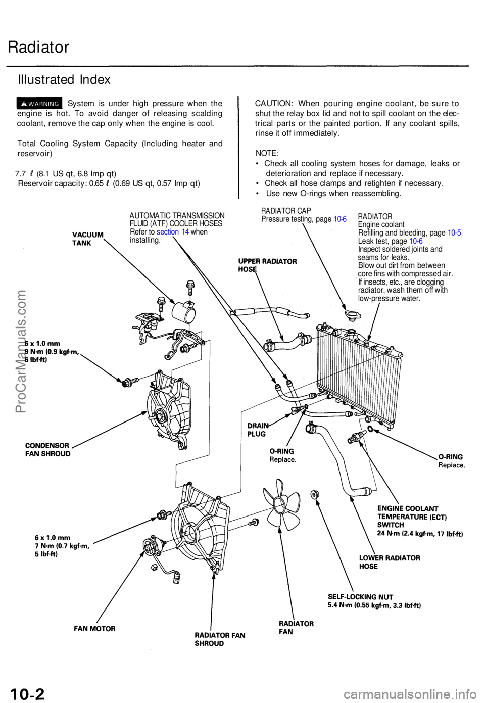
Illustrate d Inde x
Syste m is unde r hig h pressur e whe n th e
engin e i s hot . T o avoi d dange r o f releasin g scaldin g
coolant , remov e th e ca p onl y whe n th e engin e is cool .
Tota l Coolin g Syste m Capacit y (Includin g heate r an d
reservoir )
7.7 (8. 1 US qt , 6. 8 Im p qt )
Reservoi r capacity : 0.6 5 (0.6 9 U S qt , 0.5 7 Im p qt ) CAUTION
: Whe n pourin g engin e coolant , b e sur e t o
shu t th e rela y bo x li d an d no t t o spil l coolan t o n th e elec -
trica l part s o r th e painte d portion . I f an y coolan t spills ,
rins e it of f immediately .
NOTE:
• Chec k al l coolin g syste m hose s fo r damage , leak s o r
deterioratio n an d replac e if necessary .
• Chec k al l hos e clamp s an d retighte n if necessary .
• Us e ne w O-ring s whe n reassembling .
RADIATOR CA PPressur e testing , pag e 10- 6RADIATO REngine coolan t
Refillin g an d bleeding , pag e 10- 5
Leak test , pag e 10- 6Inspec t soldere d joint s an dseam s fo r leaks .Blow ou t dir t fro m betwee ncore fin s wit h compresse d air .If insects , etc. , ar e cloggin gradiator , was h the m of f wit hlow-pressur e water .
AUTOMATI C TRANSMISSIO NFLUID (ATF ) COOLE R HOSE SRefer t o sectio n 1 4 whe ninstalling .
ProCarManuals.com
Page 143 of 1771
Radiator
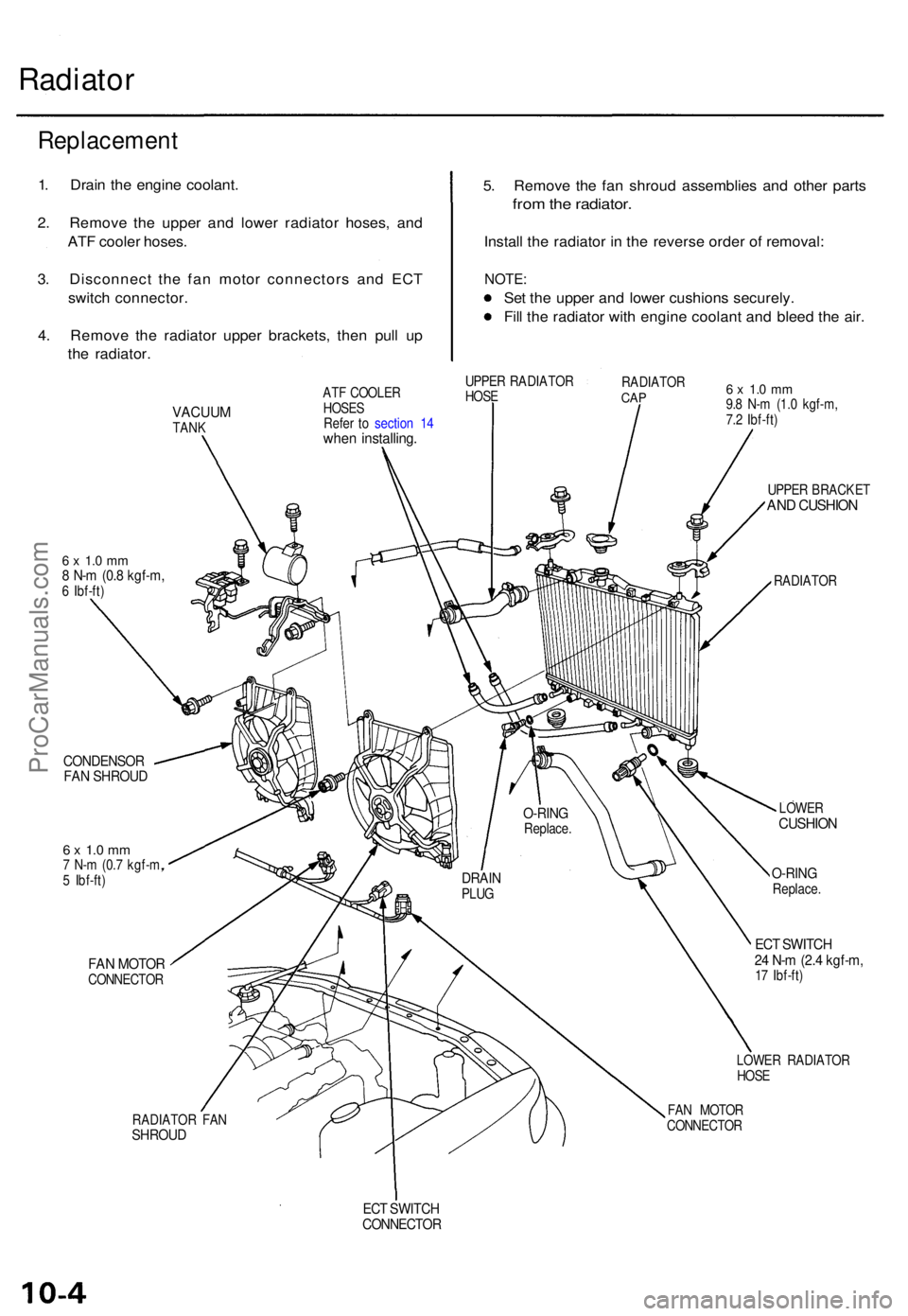
5. Remov e th e fa n shrou d assemblie s an d othe r part s
from th e radiator .
Install th e radiato r i n th e revers e orde r o f removal :
NOTE:
Set th e uppe r an d lowe r cushion s securely .
Fil l th e radiato r wit h engin e coolan t an d blee d th e air .
VACUU MTANK
6 x 1. 0 m m8 N- m (0. 8 kgf-m ,6 Ibf-ft )
CONDENSO RFAN SHROU D
6 x 1. 0 m m7 N- m (0. 7 kgf-m ,
5 Ibf-ft )
FAN MOTO RCONNECTO R
RADIATO R FA N
SHROU D
ATF COOLE R
HOSE S
Refe r t o sectio n 1 4
whe n installing .
UPPER RADIATO R
HOS E RADIATO
RCAP6 x 1. 0 m m9.8 N- m (1. 0 kgf-m ,
7. 2 Ibf-ft )
UPPE R BRACKE T
AND CUSHIO N
RADIATO R
LOWE R
CUSHIO N
O-RINGReplace .
ECT SWITC H24 N- m (2. 4 kgf-m ,17 Ibf-ft )
LOWE R RADIATO R
HOS E
FA N MOTO R
CONNECTO R
ECT SWITC HCONNECTO R
DRAINPLUG
O-RIN GReplace .
Replacemen t
1. Drai n th e engin e coolant .
2 . Remov e th e uppe r an d lowe r radiato r hoses , an d
AT F coole r hoses .
3 . Disconnec t th e fa n moto r connector s an d EC T
switc h connector .
4 . Remov e th e radiato r uppe r brackets , the n pul l u p
th e radiator .
ProCarManuals.com
Page 145 of 1771
Radiator
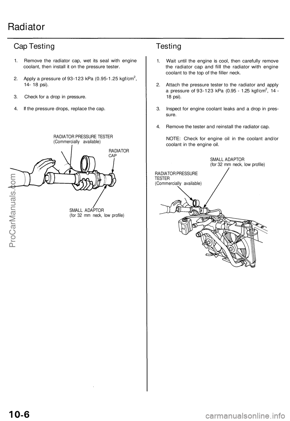
Cap Testing
1. Remove the radiator cap, wet its seal with engine
coolant, then install it on the pressure tester.
2. Apply a pressure of 93-123 kPa (0.95-1.25 kgf/cm2,
14- 18
psi).
3. Check for a drop in pressure.
4. If the pressure drops, replace the cap.
RADIATOR PRESSURE TESTER
(Commercially available)
Testing
RADIATOR
CAP
SMALL ADAPTOR
(for 32 mm neck, low profile)
1. Wait until the engine is cool, then carefully remove
the
radiator
cap and
fill
the
radiator
with
engine
coolant to the top of the filler neck.
2. Attach the pressure tester to the radiator and apply
a pressure of 93-123 kPa (0.95 - 1.25 kgf/cm2, 14 -
18
psi).
3. Inspect for engine coolant leaks and a drop in pres-
sure.
4. Remove the tester and reinstall the radiator cap.
NOTE: Check for engine oil in the coolant and/or
coolant in the engine oil.
SMALL ADAPTOR
(for 32 mm neck, low profile)
RADIATOR PRESSURE
TESTER
(Commercially available)ProCarManuals.com
Page 241 of 1771
Throttle Cable
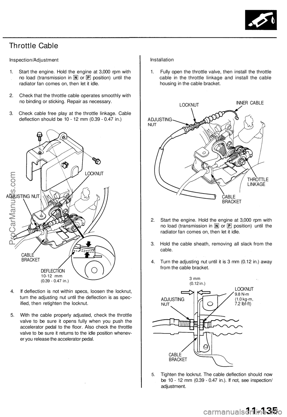
Inspection/Adjustment
1. Start the engine. Hold the engine at 3,000 rpm with
no load (transmission in or position) until the
radiator fan comes on, then let it idle.
2. Check that the throttle cable operates smoothly with
no binding or sticking. Repair as necessary.
3. Check cable free play at the throttle linkage. Cable
deflection should be 10 - 12 mm (0.39 - 0.47 in.)
ADJUSTING NUT
CABLE
BRACKET
DEFLECTION
10-12
mm
(0.39
-
0.47 in.)
4. If deflection is not within specs, loosen the locknut,
turn the adjusting nut until the deflection is as spec-
ified, then retighten the locknut.
5. With the cable properly adjusted, check the throttle
valve to be sure it opens fully when you push the
accelerator pedal to the floor. Also check the throttle
valve to be sure it returns to the idle position whenev-
er you release the accelerator pedal.
Installation
1. Fully open the throttle valve, then install the throttle
cable in the throttle linkage and install the cable
housing in the cable bracket.
LOCKNUT
INNER CABLE
ADJUSTING
NUT
THROTTLE
LINKAGE
CABLE
BRACKET
2. Start the engine. Hold the engine at 3,000 rpm with
no load (transmission in or position) until the
radiator fan comes on, then let it idle.
3. Hold the cable sheath, removing all slack from the
cable.
4. Turn the adjusting nut until it is 3 mm (0.12 in.) away
from the cable bracket.
3 mm
(0.12 in.)
ADJUSTING
NUT
LOCKNUT
9.8 N-m
(1.0 kg-m,
7.2 Ibf-ft)
5.
CABLE
BRACKET
Tighten the locknut. The cable deflection should now
be 10 - 12 mm (0.39 - 0.47 in.). If not, see inspection/
adjustment.
LOCKNUTProCarManuals.com
Page 327 of 1771
Stall Speed
Test
CAUTION:
To prevent transmission damage, do not test stall speed for more than 10 seconds at a time.
Do not shift the lever while raising the engine speed.
Be sure to remove the pressure gauge before testing stall speed.
1. Engage the parking brake, and block the front wheels.
2. Connect a tachometer to the engine, and start the engine.
3. Make sure the A/C switch is OFF.
4. After the engine has warmed up to normal operating temperature (the radiator fan comes on), shift into [2] position.
5. Fully depress the brake pedal and accelerator for 6 to 8 seconds, and note engine speed.
6. Allow two minutes for cooling, then repeat the test in , , and positions.
NOTE:
• Stall speed tests should be used for diagnostic purposes only.
• Stall speed should be the same in , and positions.
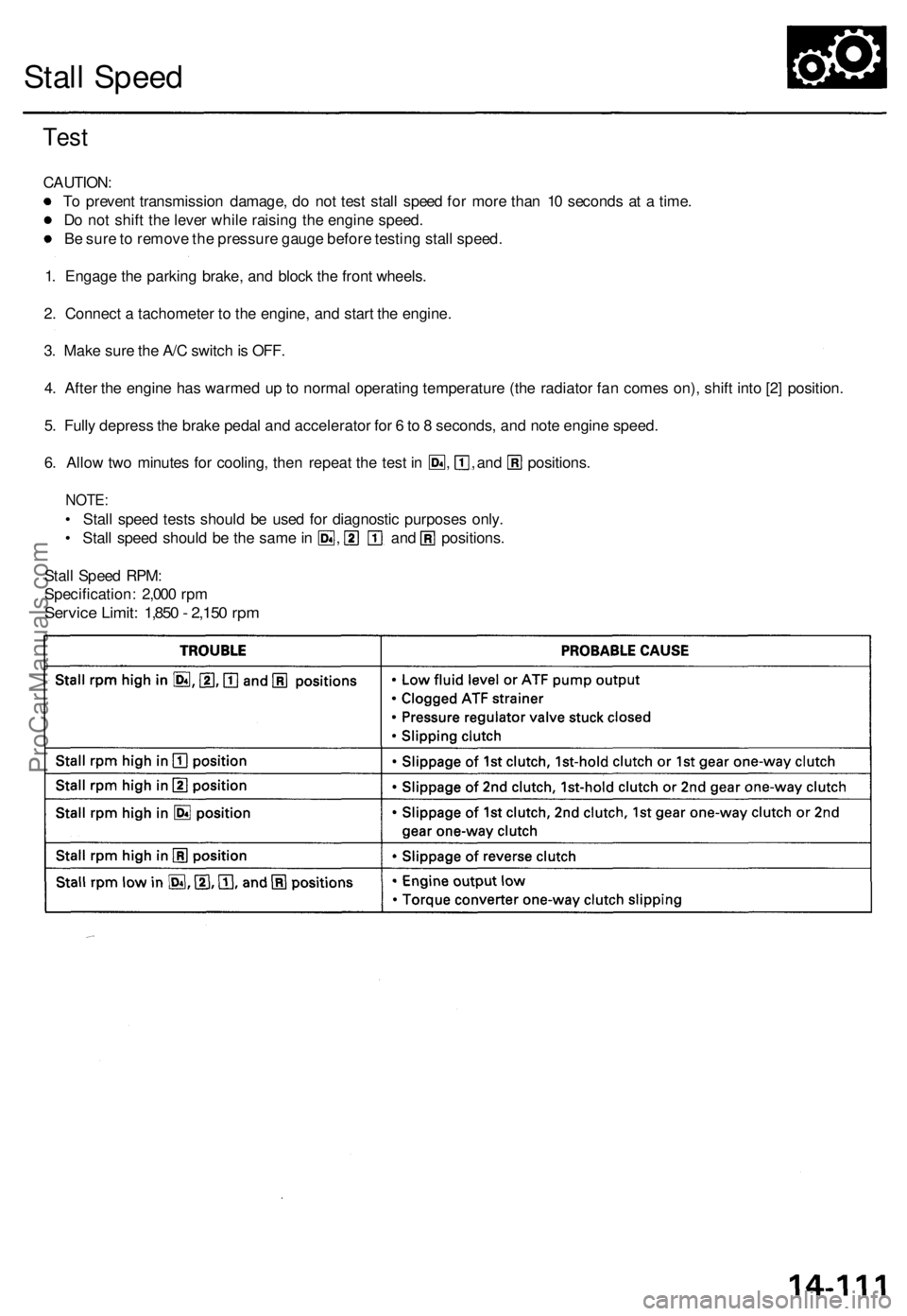
Stall Speed RPM:
Specification: 2,000 rpm
Service Limit: 1,850 - 2,150 rpmProCarManuals.com
Page 328 of 1771
Fluid Level
Checking/Changing
Checking
NOTE: Check the fluid level with the engine at normal
operating temperature (the radiator fan comes on).
1. Park the vehicle on level ground. Turn off the
engine.
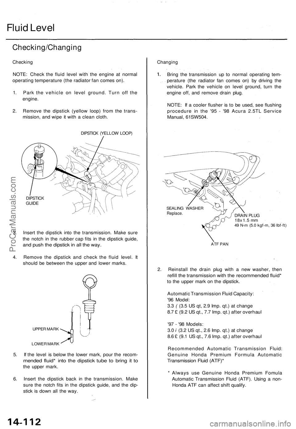
2. Remove the dipstick (yellow loop) from the trans-
mission, and wipe it with a clean cloth.
DIPSTICK (YELLOW LOOP)
DIPSTICK
GUIDE
3. Insert the dipstick into the transmission. Make sure
the notch in the rubber cap fits in the dipstick guide,
and push the dipstick in all the way.
4. Remove the dipstick and check the fluid level. It
should be between the upper and lower marks.
UPPER MARK
LOWER MARK
5. If the level is below the lower mark, pour the recom-
mended fluid* into the dipstick tube to bring it to
the upper mark.
6. Insert the dipstick back in the transmission. Make
sure the notch fits in the dipstick guide, and the dip-
stick is down all the way.
Changing
Bring the transmission up to normal operating tem-
perature (the radiator fan comes on) by driving the
vehicle. Park the vehicle on level ground, turn the
engine off, and remove drain plug.
NOTE: If a cooler flusher is to be used, see flushing
procedure in the '95 - '98 Acura 2.5TL Service
Manual, 61SW504.
SEALING WASHER
Replace.
DRAIN PLUG
18x1.5 mm
49 N-m (5.0 kgf-m, 36 Ibf-ft)
ATF PAN
2. Reinstall the drain plug with a new washer, then
refill the transmission with the recommended fluid*
to the upper mark on the dipstick.
Automatic Transmission Fluid Capacity:
'96 Model:
3.3 ( (3.5 US qt, 2.9 Imp. qt.) at change
8.7 £ (9.2 US qt., 7.7 Imp. qt.) after overhaul
'97 - '98 Models:
3.0 i (3.2 US qt., 2.6 Imp. qt.) at change
8.6 £ (9.1 US qt., 7.6 Imp. qt.) after overhaul
Recommended Automatic Transmission Fluid:
Genuine Honda Premium Formula Automatic
Transmission Fluid (ATF)*
* Always use Genuine Honda Premium Fomula
Automatic Transmission Fluid (ATF). Using a non-
Honda ATF can affect shift qualify.ProCarManuals.com
Page 562 of 1771
Troubleshooting
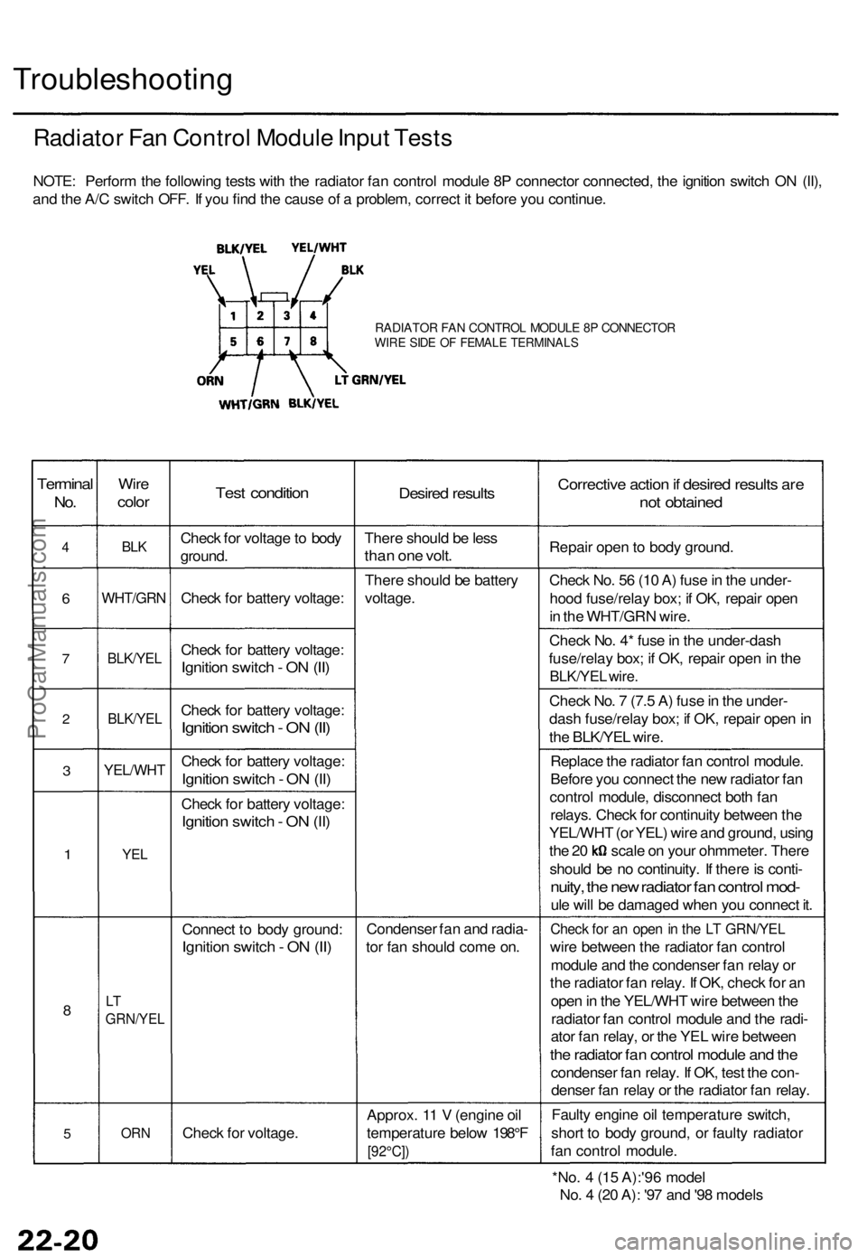
Radiator Fan Control Module Input Tests
NOTE: Perform the following tests with the radiator fan control module 8P connector connected, the ignition switch ON (II),
and the A/C switch OFF. If you find the cause of a problem, correct it before you continue.
RADIATOR FAN CONTROL MODULE 8P CONNECTOR
WIRE SIDE OF FEMALE TERMINALS
Terminal
No.
4
6
7
2
3
1
8
5
Wire
color
BLK
WHT/GRN
BLK/YEL
BLK/YEL
YEL/WHT
YEL
LT
GRN/YEL
ORN
Test condition
Check for voltage to body
ground.
Check for battery voltage:
Check for battery voltage:
Ignition switch - ON (II)
Check for battery voltage:
Ignition switch - ON (II)
Check for battery voltage:
Ignition switch - ON (II)
Check for battery voltage:
Ignition switch - ON (II)
Connect to body ground:
Ignition switch - ON (II)
Check for voltage.
Desired results
There should be less
than one volt.
There should be battery
voltage.
Condenser fan and radia-
tor fan should come on.
Approx. 11 V (engine oil
temperature below 198°F
[92°C])
Corrective action if desired results are
not obtained
Repair open to body ground.
Check No. 56 (10 A) fuse in the under-
hood fuse/relay box; if OK, repair open
in the WHT/GRN wire.
Check No. 4* fuse in the under-dash
fuse/relay box; if OK, repair open in the
BLK/YEL wire.
Check No. 7 (7.5 A) fuse in the under-
dash fuse/relay box; if OK, repair open in
the BLK/YEL wire.
Replace the radiator fan control module.
Before you connect the new radiator fan
control module, disconnect both fan
relays. Check for continuity between the
YEL/WHT (or YEL) wire and ground, using
the 20 scale on your ohmmeter. There
should be no continuity. If there is conti-
nuity, the new radiator fan control mod-
ule will be damaged when you connect it.
Check for an open in the LT GRN/YEL
wire between the radiator fan control
module and the condenser fan relay or
the radiator fan relay. If OK, check for an
open in the YEL/WHT wire between the
radiator fan control module and the radi-
ator fan relay, or the YEL wire between
the radiator fan control module and the
condenser fan relay. If OK, test the con-
denser fan relay or the radiator fan relay.
Faulty engine oil temperature switch,
short to body ground, or faulty radiator
fan control module.
*No. 4 (15 A):'96 model
No. 4 (20 A): '97 and '98 modelsProCarManuals.com
Page 610 of 1771
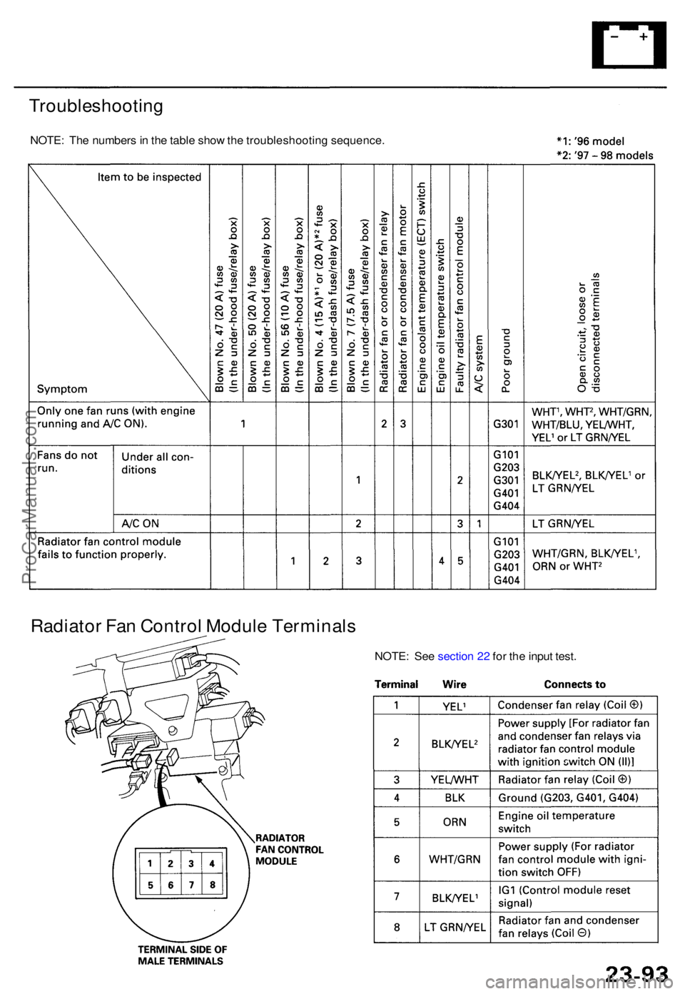
Troubleshooting
NOTE: Th e number s in th e tabl e sho w th e troubleshootin g sequence .
Radiator Fa n Contro l Modul e Terminal s
NOTE: Se e sectio n 2 2 fo r th e inpu t test .
ProCarManuals.com
Page 822 of 1771
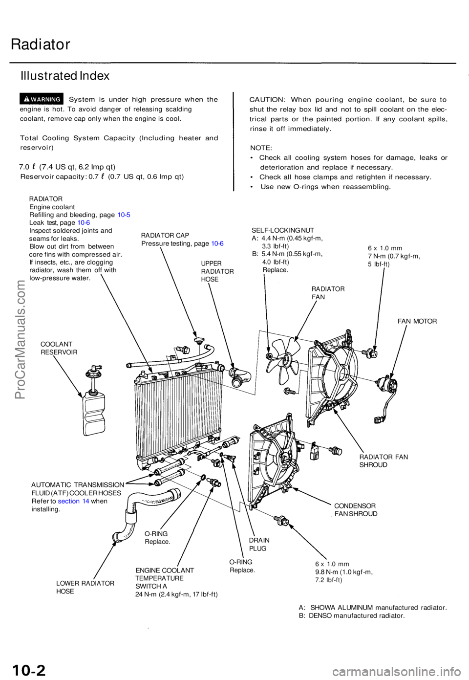
Radiator
Illustrate d Inde x
Syste m is unde r hig h pressur e whe n th e
engin e i s hot . T o avoi d dange r o f releasin g scaldin g
coolant , remov e ca p onl y whe n th e engin e i s cool .
Total Coolin g Syste m Capacit y (Includin g heate r an d
reservoir )
7.0 (7. 4 US qt , 6. 2 Im p qt )
Reservoi r capacity : 0. 7 (0. 7 U S qt , 0. 6 Im p qt )
RADIATO REngine coolan t
Refillin g an d bleeding , pag e 10- 5
Lea k test , pag e 10- 6
Inspec t soldere d joint s an d
seam s fo r leaks .
Blo w ou t dir t fro m betwee n
cor e fin s wit h compresse d air .
I f insects , etc. , ar e cloggin g
radiator , was h the m of f wit h
low-pressur e water .
CAUTION : Whe n pourin g engin e coolant , b e sur e t o
shu t th e rela y bo x li d an d no t t o spil l coolan t o n th e elec -
trica l part s o r th e painte d portion . I f an y coolan t spills ,
rins e i t of f immediately .
NOTE:
• Chec k al l coolin g syste m hose s fo r damage , leak s o r
deterioratio n an d replac e i f necessary .
• Chec k al l hos e clamp s an d retighte n i f necessary .
• Us e ne w O-ring s whe n reassembling .
RADIATOR CA PPressur e testing , pag e 10- 6
SELF-LOCKIN G NU TA: 4. 4 N- m (0.4 5 kgf-m ,3.3 Ibf-ft )B: 5. 4 N- m (0.5 5 kgf-m ,4.0 Ibf-ft )Replace .
6 x 1. 0 m m7 N- m (0. 7 kgf-m ,5 Ibf-ft )
COOLAN TRESERVOI R
FAN MOTO R
RADIATO R FA NSHROU D
AUTOMATI C TRANSMISSIO N
FLUI D (ATF ) COOLE R HOSE S
Refe r t o sectio n 1 4 whe n
installing .
CONDENSO RFAN SHROU D
LOWER RADIATO RHOSE
ENGIN E COOLAN TTEMPERATUR ESWITCH A
2 4 N- m (2. 4 kgf-m , 1 7 Ibf-ft )
O-RIN GReplace .6 x 1. 0 m m9.8 N- m (1. 0 kgf-m ,7.2 Ibf-ft )
A: SHOW A ALUMINU M manufacture d radiator .
B : DENS O manufacture d radiator .
O-RINGReplace .DRAINPLUG
UPPE RRADIATO RHOSE
RADIATO RFAN
ProCarManuals.com