alternator ACURA TL 1995 Service Repair Manual
[x] Cancel search | Manufacturer: ACURA, Model Year: 1995, Model line: TL, Model: ACURA TL 1995Pages: 1771, PDF Size: 62.49 MB
Page 47 of 1771
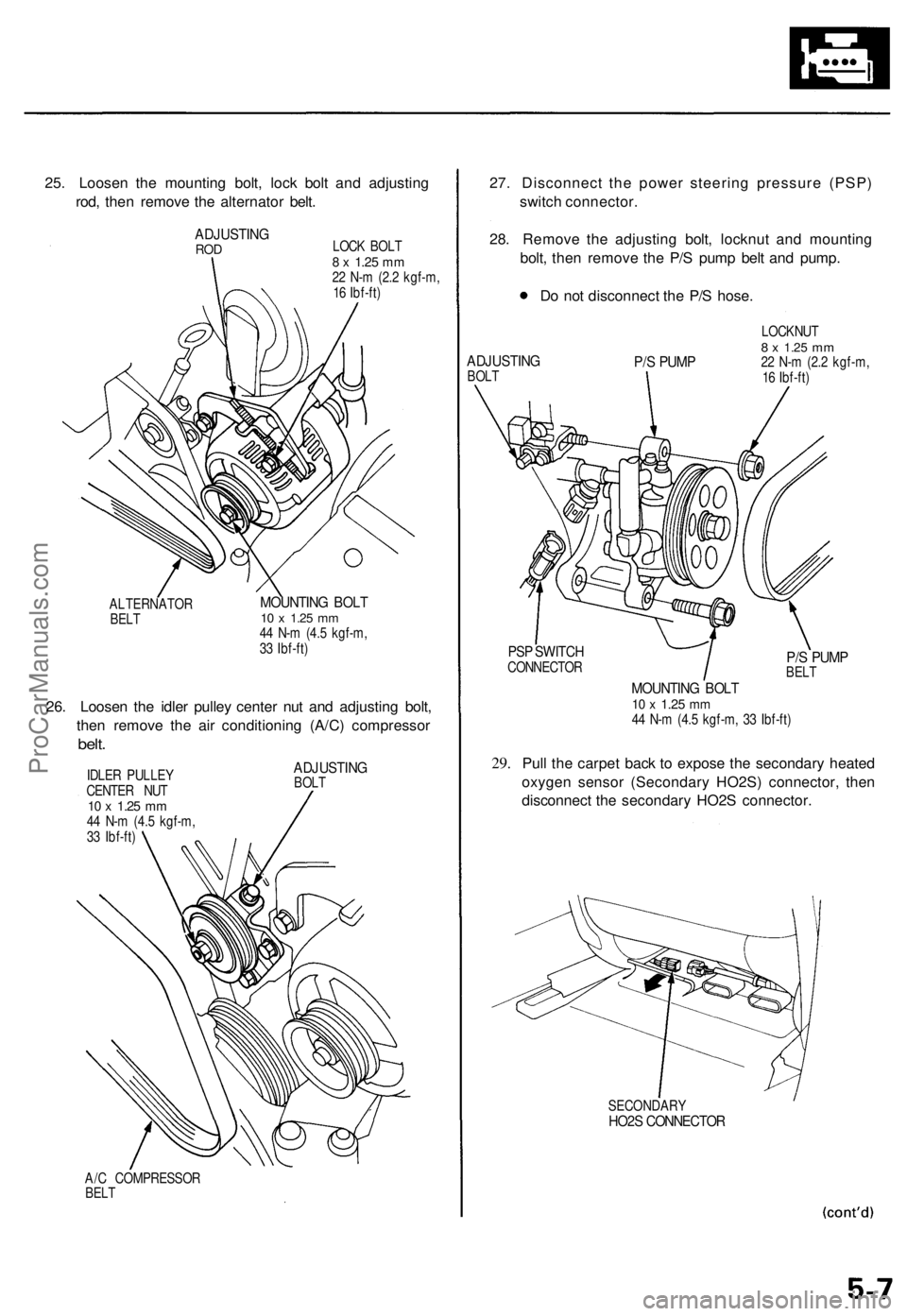
25. Loosen the mounting bolt, lock bolt and adjusting
rod, then remove the alternator belt.
ADJUSTING
ROD
LOCK BOLT
8 x
1.25
mm
22 N-m (2.2 kgf-m,
16 Ibf-ft)
ALTERNATOR
BELT
MOUNTING BOLT
10 x
1.25
mm
44 N-m (4.5 kgf-m,
33 Ibf-ft)
26. Loosen the idler pulley center nut and adjusting bolt,
then remove the air conditioning (A/C) compressor
belt.
IDLER PULLEY
CENTER NUT
10 x
1.25
mm
44 N-m (4.5 kgf-m,
33 Ibf-ft)
ADJUSTING
BOLT
A/C COMPRESSOR
BELT
27. Disconnect the power steering pressure (PSP)
switch connector.
28. Remove the adjusting bolt, locknut and mounting
bolt, then remove the P/S pump belt and pump.
Do not disconnect the P/S hose.
ADJUSTING
BOLT
P/S PUMP
LOCKNUT
8 x
1.25
mm
22 N-m (2.2 kgf-m,
16 Ibf-ft)
PSP SWITCH
CONNECTOR
29.
P/S PUMP
BELT
MOUNTING BOLT
10 x
1.25
mm
44 N-m (4.5 kgf-m, 33 Ibf-ft)
Pull the carpet back to expose the secondary heated
oxygen sensor (Secondary HO2S) connector, then
disconnect the secondary HO2S connector.
SECONDARY
HO2S CONNECTORProCarManuals.com
Page 54 of 1771
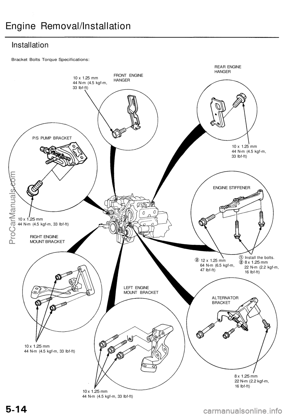
Engine Removal/Installation
Installation
Bracket Bolts Torque Specifications:
REAR ENGINE
HANGER
P/S PUMP BRACKET
10 x
1.25
mm
44 N-m (4.5 kgf-m,
33 Ibf-ft)
ENGINE STIFFENER
10 x
1.25
mm
44 N-m (4.5 kgf-m, 33 Ibf-ft)
RIGHT ENGINE
MOUNT BRACKET
LEFT ENGINE
MOUNT BRACKET
12 x
1.25
mm
64 N-m (6.5 kgf-m,
47 Ibf-ft)
Install the bolts.
8 x
1.25
mm
22 N-m (2.2 kgf-m,
16 Ibf-ft)
ALTERNATOR
BRACKET
10 x
1.25
mm
44 N-m (4.5 kgf-m, 33 Ibf-ft)
8 x
1.25
mm
22 N-m (2.2 kgf-m,
16 Ibf-ft)
10 x
1.25
mm
44 N-m (4.5 kgf-m, 33 Ibf-ft)
10 x
1.25
mm
44 N-m (4.5 kgf-m,
33 Ibf-ft)
FRONT ENGINE
HANGERProCarManuals.com
Page 78 of 1771
Cylinder Heads
Removal (cont'd)
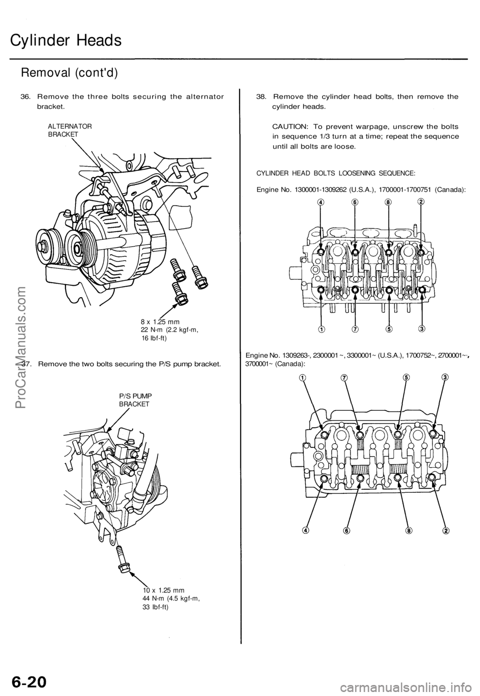
36. Remove the three bolts securing the alternator
bracket.
ALTERNATOR
BRACKET
8 x
1.25
mm
22 N-m (2.2 kgf-m,
16 Ibf-ft)
37. Remove the two bolts securing the P/S pump bracket.
P/S PUMP
BRACKET
10 x
1.25
mm
44 N-m (4.5 kgf-m,
33 Ibf-ft)
38. Remove the cylinder head bolts, then remove the
cylinder heads.
CAUTION: To prevent warpage, unscrew the bolts
in sequence 1/3 turn at a time; repeat the sequence
until all bolts are loose.
CYLINDER HEAD BOLTS LOOSENING SEQUENCE:
Engine No. 1300001-1309262 (U.S.A.), 1700001-1700751 (Canada):
Engine No. 1309263-, 2300001 ~, 3300001~ (U.S.A.), 1700752~, 2700001~
3700001~ (Canada):ProCarManuals.com
Page 601 of 1771
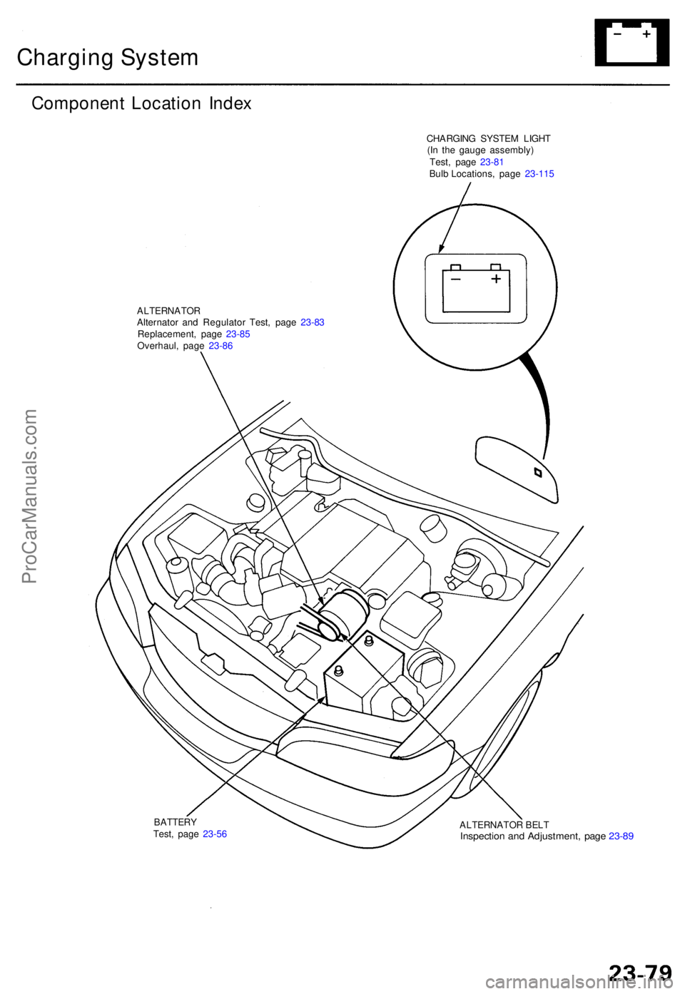
Charging Syste m
Componen t Locatio n Inde x
CHARGIN G SYSTE M LIGH T
(I n th e gaug e assembly )
ALTERNATO RAlternator an d Regulato r Test , pag e 23-8 3
Replacement , pag e 23-8 5
Overhaul , pag e 23-8 6
ALTERNATOR BEL T
Inspectio n an d Adjustment , pag e 23-8 9
BATTER YTest, pag e 23-5 6 Test
, pag e 23-8 1
Bulb Locations , pag e 23- 115
ProCarManuals.com
Page 602 of 1771
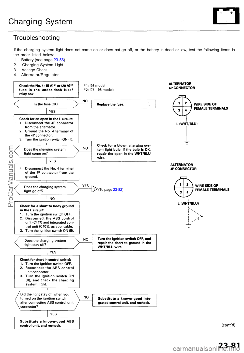
Charging Syste m
Troubleshootin g
If th e chargin g syste m ligh t doe s no t com e o n o r doe s no t g o off , o r th e batter y i s dea d o r low , tes t th e followin g item s i n
th e orde r liste d below :
1 . Batter y (se e pag e 23-56 )
2 . Chargin g Syste m Ligh t
3. Voltag e Chec k
4. Alternator/Regulato r
(To page 23-82 )
ProCarManuals.com
Page 603 of 1771
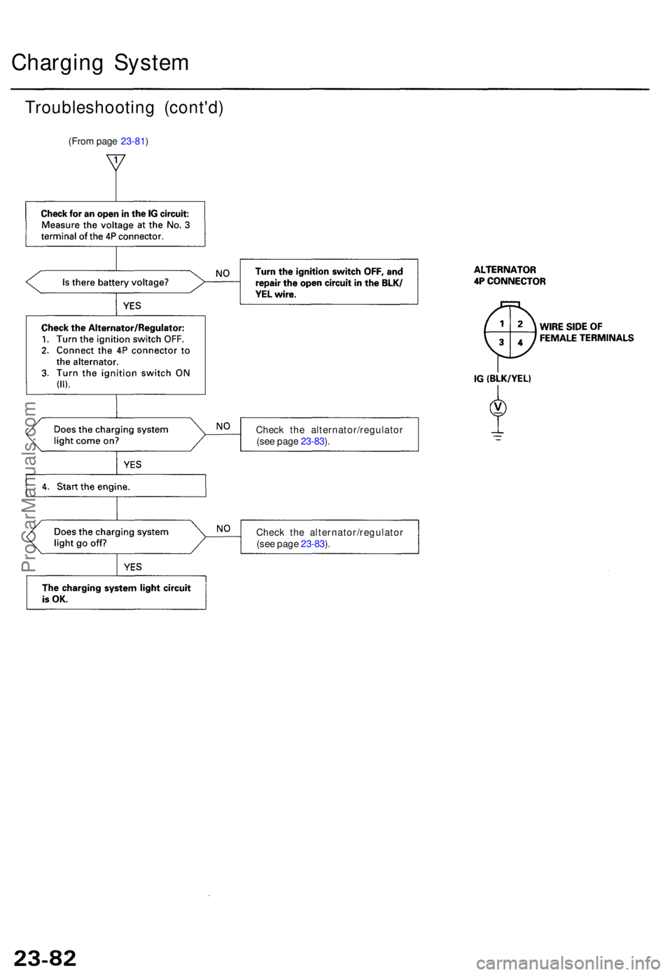
Charging Syste m
Troubleshootin g (cont'd )
(From page 23-81 )
Check th e alternator/regulato r
(se e pag e 23-83 ).
Chec k th e alternator/regulato r
(se e pag e 23-83 ).
ProCarManuals.com
Page 605 of 1771
Charging Syste m
Troubleshootin g (cont'd )
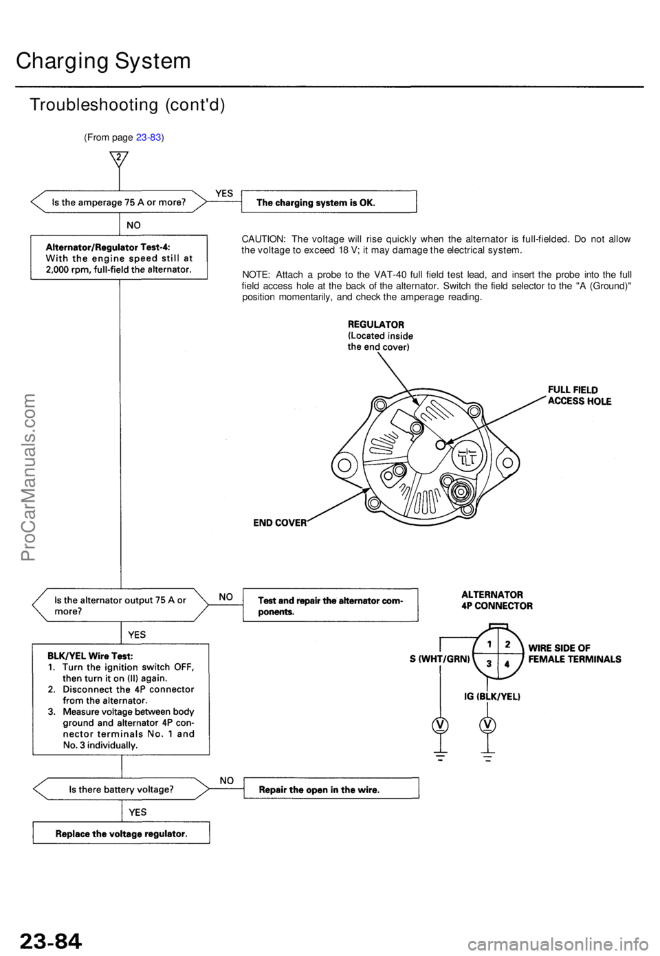
(From page 23-83 )
CAUTION: Th e voltag e wil l ris e quickl y whe n th e alternato r i s full-fielded . D o no t allo w
th e voltag e to excee d 1 8 V ; i t ma y damag e th e electrica l system .
NOTE : Attac h a prob e t o th e VAT-4 0 ful l fiel d tes t lead , an d inser t th e prob e int o th e ful l
fiel d acces s hol e a t th e bac k o f th e alternator . Switc h th e fiel d selecto r t o th e " A (Ground) "
positio n momentarily , an d chec k th e amperag e reading .
ProCarManuals.com
Page 606 of 1771
Alternator Replacemen t
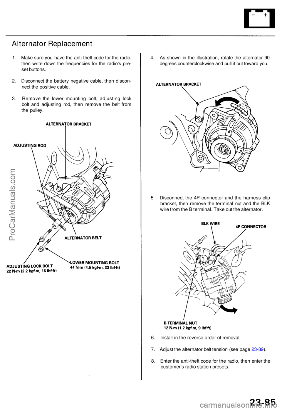
1. Mak e sur e yo u hav e th e anti-thef t cod e fo r th e radio ,
the n writ e dow n th e frequencie s fo r th e radio' s pre -
set buttons .
2. Disconnec t th e batter y negativ e cable , the n discon -
nec t th e positiv e cable .
3 . Remov e th e lowe r mountin g bolt , adjustin g loc k
bol t an d adjustin g rod , the n remov e th e bel t fro m
th e pulley . 4
. A s show n i n th e illustration , rotat e th e alternato r 9 0
degree s counterclockwis e an d pul l i t ou t towar d you .
5 . Disconnec t th e 4 P connecto r an d th e harnes s cli p
bracket , the n remov e th e termina l nu t an d th e BL K
wir e fro m th e B terminal . Tak e ou t th e alternator .
6 . Instal l i n th e revers e orde r o f removal .
7 . Adjus t th e alternato r bel t tensio n (se e pag e 23-89 ).
8 . Ente r th e anti-theft code fo r th e radio , the n ente r th e
customer' s radi o statio n presets .
ProCarManuals.com
Page 608 of 1771
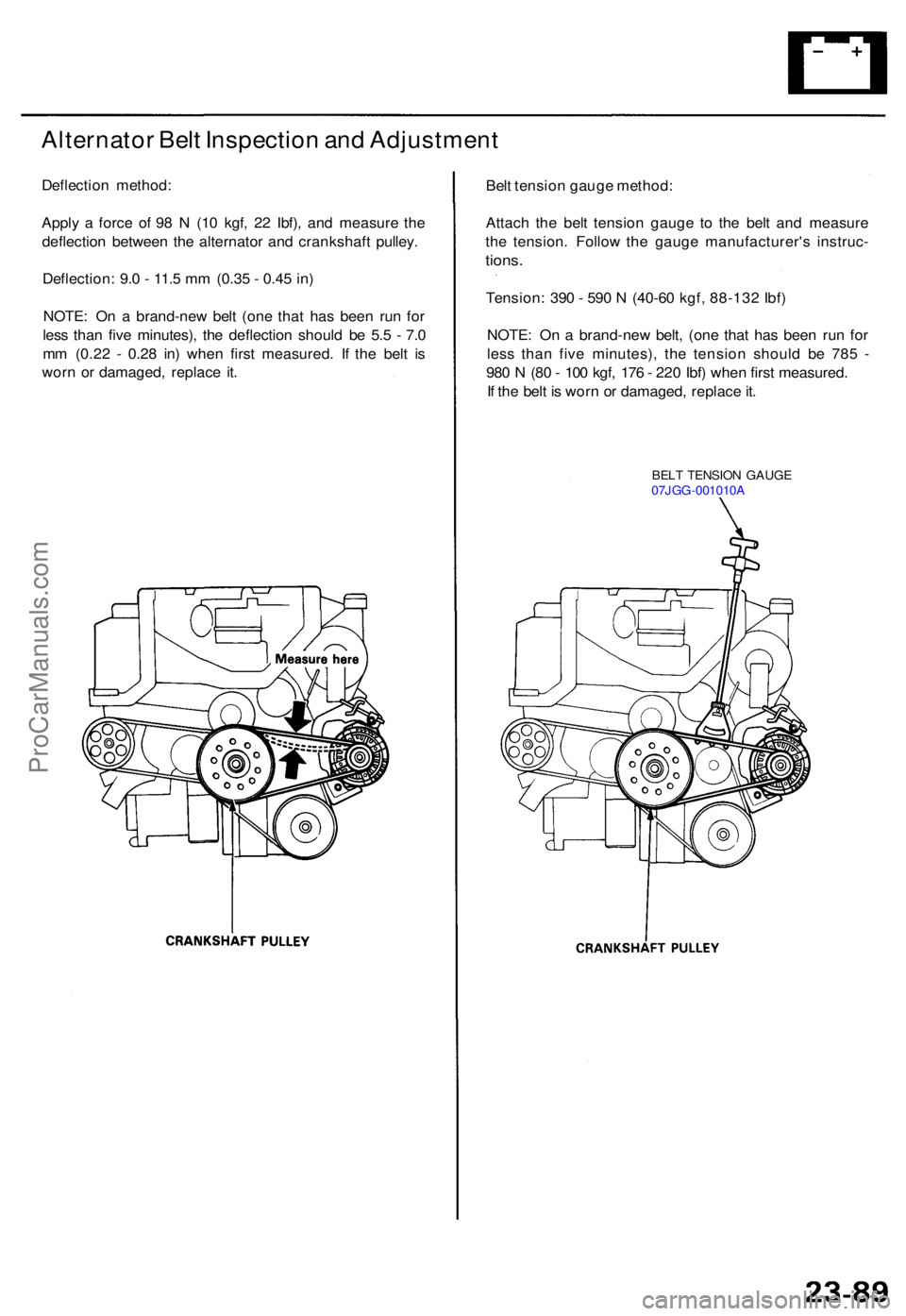
Alternator Bel t Inspectio n an d Adjustmen t
Deflection method :
Appl y a forc e o f 9 8 N (1 0 kgf , 2 2 Ibf) , an d measur e th e
deflectio n betwee n th e alternato r an d crankshaf t pulley .
Deflection : 9. 0 - 11. 5 m m (0.3 5 - 0.4 5 in )
NOTE : O n a brand-ne w bel t (on e tha t ha s bee n ru n fo r
les s tha n fiv e minutes) , th e deflectio n shoul d b e 5. 5 - 7. 0
m m (0.2 2 - 0.2 8 in ) whe n firs t measured . I f th e bel t i s
wor n o r damaged , replac e it . Bel
t tensio n gaug e method :
Attac h th e bel t tensio n gaug e t o th e bel t an d measur e
th e tension . Follo w th e gaug e manufacturer' s instruc -
tions.
Tension : 39 0 - 59 0 N (4 0-6 0 kgf , 88-13 2 Ibf )
NOTE : O n a brand-ne w belt , (on e tha t ha s bee n ru n fo r
les s tha n fiv e minutes) , th e tensio n shoul d b e 78 5 -
98 0 N (8 0 - 10 0 kgf , 17 6 - 22 0 Ibf ) whe n firs t measured .
I f th e bel t i s wor n o r damaged , replac e it .
BEL T TENSIO N GAUG E
07JG G-001010 A
ProCarManuals.com
Page 877 of 1771
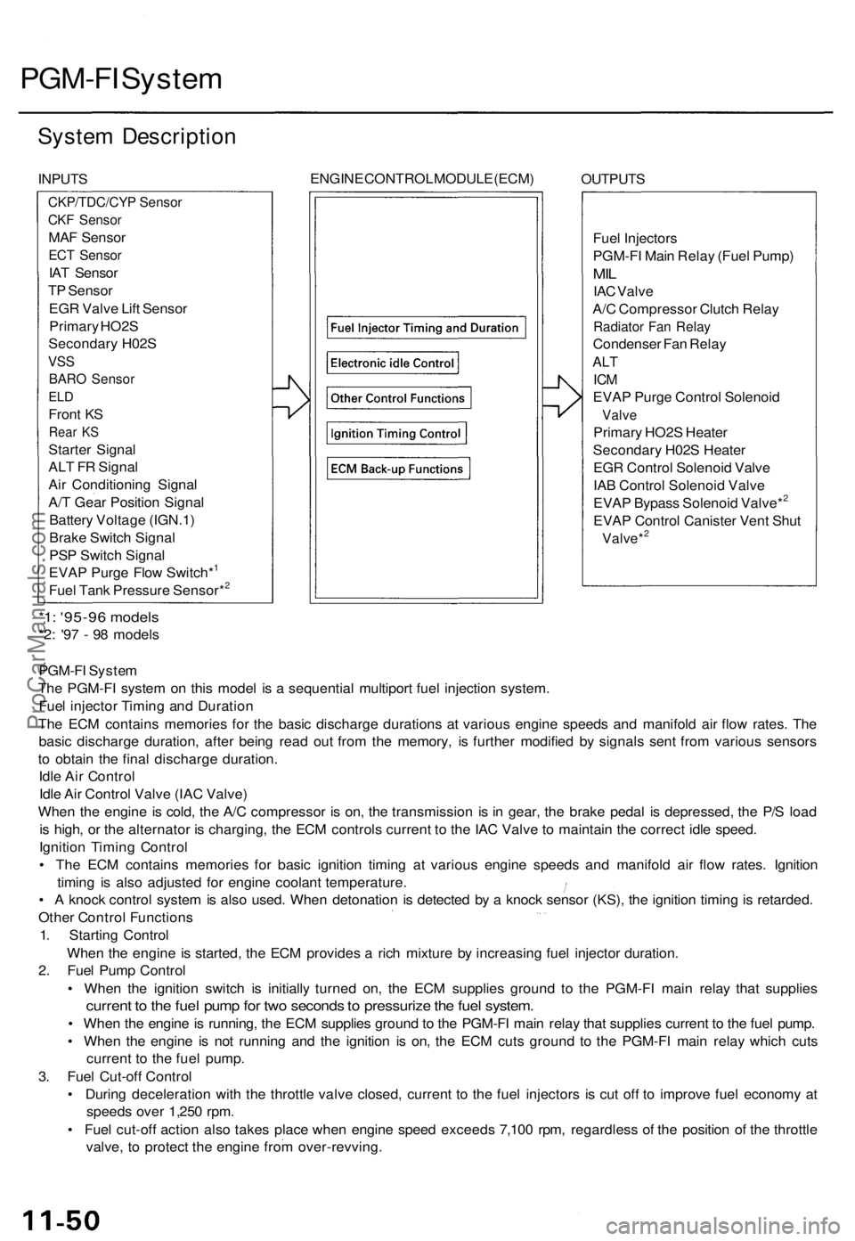
PGM-FI System
System Description
INPUTS
ENGINE CONTROL MODULE (ECM)
OUTPUTS
Fuel Injectors
PGM-FI Main Relay (Fuel Pump)
MIL
IAC Valve
A/C Compressor Clutch Relay
Radiator Fan Relay
Condenser Fan Relay
ALT
ICM
EVAP Purge Control Solenoid
Valve
Primary HO2S Heater
Secondary H02S Heater
EGR Control Solenoid Valve
IAB Control Solenoid Valve
EVAP Bypass Solenoid Valve*2
EVAP Control Canister Vent Shut
Valve*2
*1: '95-96 models
*2: '97 - 98 models
PGM-FI System
The PGM-FI system on this model is a sequential multiport fuel injection system.
Fuel injector Timing and Duration
The ECM contains memories for the basic discharge durations at various engine speeds and manifold air flow rates. The
basic discharge duration, after being read out from the memory, is further modified by signals sent from various sensors
to obtain the final discharge duration.
Idle Air Control
Idle Air Control Valve (IAC Valve)
When the engine is cold, the A/C compressor is on, the transmission is in gear, the brake pedal is depressed, the P/S load
is high, or the alternator is charging, the ECM controls current to the IAC Valve to maintain the correct idle speed.
Ignition Timing Control
• The ECM contains memories for basic ignition timing at various engine speeds and manifold air flow rates. Ignition
timing is also adjusted for engine coolant temperature.
• A knock control system is also used. When detonation is detected by a knock sensor (KS), the ignition timing is retarded.
Other Control Functions
1. Starting Control
When the engine is started, the ECM provides a rich mixture by increasing fuel injector duration.
2. Fuel Pump Control
• When the ignition switch is initially turned on, the ECM supplies ground to the PGM-FI main relay that supplies
current to the fuel pump for two seconds to pressurize the fuel system.
• When the engine is running, the ECM supplies ground to the PGM-FI main relay that supplies current to the fuel pump.
• When the engine is not running and the ignition is on, the ECM cuts ground to the PGM-FI main relay which cuts
current to the fuel pump.
3. Fuel Cut-off Control
• During deceleration with the throttle valve closed, current to the fuel injectors is cut off to improve fuel economy at
speeds over 1,250 rpm.
• Fuel cut-off action also takes place when engine speed exceeds 7,100 rpm, regardless of the position of the throttle
valve, to protect the engine from over-revving.
CKP/TDC/CYP Sensor
CKF Sensor
MAF Sensor
ECT Sensor
IAT Sensor
TP Sensor
EGR Valve Lift Sensor
Primary HO2S
Secondary H02S
VSS
BARO Sensor
ELD
Front KS
Rear KS
Starter Signal
ALT FR Signal
Air Conditioning Signal
A/T Gear Position Signal
Battery Voltage (IGN.1)
Brake Switch Signal
PSP Switch Signal
EVAP Purge Flow Switch*1
Fuel Tank Pressure Sensor*2ProCarManuals.com